of inadvertant application of deadly force. Innovative use of barriers to decrease mobility of opposing forces and active use of barriers to cause opposing forces ...
Advanced Nonlinear and Hybrid Systems Control Technology
TECHNICAL PROGRESS REPORT
Wolf Kohn Jeffrey Remmel Vladimir Brayman John James Anil Nerode
August 1996
U.S. Army Armaments Research Development and Engineering Center Picatinny Arsenal Dover, New Jersey
Contract Number DFAAE30-96-C-0042
Sagent Corporation 11201 S.E. 8th Street, Bldg J, Suite 140 Bellevue, WA. 98004-6420 Phone: 206-637-1180 Fax: 206-637-1319
APPROVED FOR PUBLIC RELEASE DISTRIBUTION UNLIMITED
1
Introduction
This report presents the first phase of a study for implementing autonomous distributed control for the battlefield problem. The study is carried out in the context of a synchronized firing scenario involving the ATB 1000 laboratory test fixture that emulates the firing gun and a platoon leader implemented as an intelligent agent which has access to battlefield sensory information and generates firing decision actions. These actions are transmitted and processed by an agent controlling the ATB actuator. The agent controlling the ATB emulator processes the platoon leader commands by translating them into instructions for target search identification and tracking. It also processes and executes firing commands. This two-agent distributed control problem is used as a prototype of the general distributed battlefield control problem. This report also provides a proposal of a demonstration of these results via the construction of a real-time hardware prototype of agent controllers. This prototype will be based on a DSP implementation of Sagent’s Multiple Agent Hybrid Control Architecture (MAHCA) which will interface with a network of other hardware and software devices which include the ARDEC test fixture and an external generator of scenarios of events which model a subset of typical logic constraints imposed by the battlefield situation and which helps determine correct solutions of the target engagement problem. The Army is progressing towards fielding the world’s first digitized maneuver force: Army XXI. While capabilities of the first digital division are yet to be fully determined, it is expected that future Army combat operations will increasingly involve synchronizing operations with coalition forces and that future Army missions will increasingly require conduct of operations other than war (OOTW), such as peacemaking, peacekeeping, humanitarian support, and humanitarian relief. Also, current plans to reduce force structure is causing the Army to investigate increasing flexibility of existing units to support a wide range of missions. Each of these possible missions require that the Army maintains its ability to dominate the maneuver battle and they all share the common thread of the need to increase the lethality of engagement scenarios while decreasing the likelihood of inadvertant application of deadly force. Innovative use of barriers to decrease mobility of opposing forces and active use of barriers to cause opposing forces to move in desired directions has been a historic discriminator between success and failure in war. Barriers, such as intelligent mines, are often used to channel opposing forces into an area where they can be engaged by direct and indirect fire weapons of the combined arms team. Successful demonstration of command and control of advanced mines will provide commanders with a flexible, lightweight means of increasing combat effectiveness. The Army experts in mine warfare determine the critical operational issues and criteria for success of the intelligent minefield. Future efforts to coordinate results of our current demonstration of target engagement with the intelligent minefield will provide an opportunity to test concepts for 1
dominating the maneuver battle with concepts for operational use of intelligent mines. The limited scope of the Phase I SBIR project has led to simplifications of the environment and the operational context. The effort has resulted in expanding the model developed under the Defense Advanced Research Projects Agency (DARPA) Domain-Specific Software Architecture (DSSA) program without committing excessive resources to a high-fidelity model. Specifically Phase I has: 1. Determined custom, i.e., problem-dependent, requirements in the generic architecture previously developed for multiple-agent hybrid control of distributed, real-time processes, 2. Created a generic customizable procedure implemented in MAHCA for synchronization of engagement processes conducted simultaneously by heterogeneous weapon platforms, 3. Developed a generic schema for attaining synchronization of battlefield engagement processes based on a Sagent-developed estimation procedure [30], 4. Constructed a high fidelity phase coherent model for precision control of angular position of the ARDEC test fixture, and 5. Explicitly stated how to synchronize criteria for rigorous integration of low-level pointing control with the higher-level logic of battlefield estimation and engagement control processes. Specific objectives of the Phase II project are: 1. Design and implement a Digital Signal Processor implementation of the MAHCA controller suitable for integration with the ARDEC environment, 2. Construct a model of the external position, velocity and activity information available to the local engagement control via automatic distribution through appliques, 3. Use the Sagent DSP-based external control component with the ARDEC test fixture to demonstrate on-line hybrid control of angular position of a flexible beam, 4. Demonstrate resrcheduling of real-time processes, 5. Demonstrate structural adaptation of model in the presence of knowledge and parameter uncertainties, 6. Demonstrate structural adaptation (i.e., automatic reconstruction of the system model from basis model objects) in the presence of model structural uncertainty,
2
7. Demonstrate synchronization of the hybrid control of the flexible beam with engagement scenario logic, and 8. Demonstrate use of the Equational Reactive Inferencer syntax as an appropriate architectural description language for simultaneously capturing the logic and the dynamics of the target engagement domain. While our multiple-agent hybrid control theory admits the construction of high-fidelity models we will not achieve that in a Phase II demonstration of the results achieved in the modeling and simulation results achieved in Phase I. What we will achieve is a unification of logic models often used by computer scientists to define finite state machines ignore system dynamics and the differential operator equations used by control engineers to define system dynamics ignoro system logic. Additionally, incremental expansion of MAHCA models can be achieved due to the implementation of the MAHCA architecture by an extractive technology for achieving continuity with respect to the requirements. This extractive technology enables on-line reaction to adapt to new values of system state parameters. We apply an established optimization procedure (relaxed variational control — see [51]) to the system of equations describing our hybrid control architecture to extract an optimization automaton after appropriate embedding of the logic equations in the continuum representation. This result will demonstrate the on-line extraction of automata which implement distributed, intelligent, real-time control. The outline of this report is as follows. In sections 2 and 3 we will describe the Multiple Agent Hybrid Control Architecture (MAHCA) and the relaxed variational model that underlies the operation of a MAHCA agent. In section 4, we shall describe some of our earlier efforts to provide a demonstration of MAHCA by controlling a simulated battlefield engagement problem. In section 5, we shall give the specification of the ATB 1000 and in section 6, we provide detailed equations of our model of the ATB 1000. In section 7, we shall describe in more detail the operation of MAHCA agent which will be implemented in a DSP. In section 8, we will give a brief description of Sagent’s proposed control board for the ATB 1000. In section 9, we shall describe our proposal to do some preliminary testing of the MAHCA agent solutions for the problem of precision angular positioning of direct-fire weapons as represented as perturbation control of the angular position of the tip of a flexible beam of the ATB 1000. In section 10, we shall describe our proposal to coordinate and synchronize applications of MAHCA with external appliques which are being developed by the Army. Finally in section 11, we will present our conclusions.
2
The Multiple Agent Hybrid Control Architecture
In this section, we describe the main operational and functional characteristics an agent in a MAHCA network. As we mentioned in the introduction, our
3
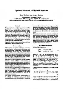
Multiple Agent Hybrid Control Architecture is implemented as a distributed system composed of agents and a communication network which we call the logic communication network. The architecture realizing this system operates as an on-line distributed theorem prover. At any update time, each active agent generates control actions as side effects of proving an existentially quantified subtheorem (lemma) which encodes the model of the plant as viewed by the agent. The conjunction of lemmas at each instant of time, encodes the desired behavior of the entire network. Each agent of MAHCA consists of five modules: a Planner, a Dynamic Knowledge Base, a Deductive Inferencer, an Adapter and a Knowledge Decoder. We briefly overview the functionality of an agent in terms of its modules. Communiction Network Interagent Communication …
Sensor Agents Sensors
Plant
Figure 1: MAHCA Framework
Agent Actions
Goal
Plan
Planner
Agent Network
Knowledge Decoder
Sensors
Correction Terms
Adapter
Inferencer
Knowledge Base
Failure Terms
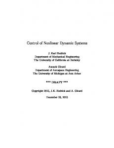
Figure 2: MAHCA Agent Architecture
The MAHCA framework is given in figure 1. The basic architecture of an MAHCA agent is pictured in figure 2. The agent consists of 5 modules with the 4
following functionality: 1. Planner The Planner constructs and repairs the agent optimization criteria which we refer to as the Lagrangian associated with the agent. In particular, the Planner generates a statement representing the desired model of the system as an existentially quantified logic expression herein referred to as the Behavior Statement. 2. Inferencer The Inferencer determines whether there is solution for the agent’s relaxed variational control problem which is a near optimal solution where the agent’s Lagrangian is used as a cost function. If there is such a solution, the agent infers a near optimal solution and sends data to the other agents. Otherwise it infers failure terms and a new state for the agent and reports the failure to the other agents. In particular, the Inferencer determines whether the Behavior Statement is a theorem in the theory currently active in the Knowledge Base. If the Behavior Statement logically follows from the current status of the Knowledge Base, the inferencer generates, as a side effect of proving this Behavior Statement to be true, the current control for the plant. If the Control Statement does not logically follow from the current status of the Knowledge Base, that is, the desired behavior is not realizable, the inferencer transmits the failed terms to the Adapter module for replacement or modification. 3. Adapter The Adapter repairs failure terms and constructs correction terms. 4. Knowledge Base The Knowledge Base stores and updates the agent’s plant model and constraints. The Knowledge Base also stores the requirements of operations or processes within the scope of the agent’s control problem. It also encodes system constraints, interagent protocols and constraints, sensory data, operational and logic principles and a set of primitive inference operations defined in the domain of equational terms. 5. Knowledge Decoder The Knowledge Decoder receives and translates the other agent’s data. To better understand, how these five modules function, we first need to discuss the basic elements of an agent’s model and how it mehaves. We will discuss this model in the next subsection and we will then follow with a more detailed discussion of the five modules of a MAHCA agent.
2.1
A MAHCA Agent’s Model
In general, a hybrid system has a hybrid state, the simultaneous dynamical state of all plants and digital control devices. Properly construed, the collection of hybrid states will form a differentiable manifold which we call the carrier manifold of the system. To incorporate the digital states as certain coordinates of the points of the carrier manifold, we “continualize” the digital states. That 5
is, we view the digital states as finite, real-valued, piecewise-constant functions of continuous time and then we take smooth approximations to them. This also allows us to consider logical and differential or variational constraints on the same footing, each restricting the points allowed on the carrier manifold. In fact, all logical or discontinuous features can be continualized withou practical side-effects. This is physically correct since for any semiconductor chip used in an analog device, the zeros and ones are really just abbreviations for sensor readings of the continuous statet of the chip. Every constraint of the system, digital or continuous, is incorporated into the definition of what points are on the carrier manifold. Lagrange constraints are regarded as part of the definition of the manifold as well, being restrictions on what points are on the manifold. More specifically, let Ai , i = 1, . . . , N (t) denote the agents active at the current time t. In our model, t takes values on the real line. At each time t, the status of each agent in the network is given by a point in a locally differentiable manifold M [24]. The Lagrangian Li of an active agent Ai is given by a continuous function, Li : M × T → R+ (1) where T is the real line (time space) and R+ is the positive real line. A point p in the manifold M is represented by a data structure of the form:
p(id, proc(proc_data), state(state_data), in(synch_data), mp(mult_data)) (2) Here id is an identifier taking values in a finite set ID, proc() is a relation characterizing plant processes status which depends on a list of parameters labeled proc_data, whose parameters define the operational, load, and timing characteristics of the process involved. The relation state captures attributes of the plant being represented which depends on a list of parameters labeled state_data whose parameters, among other things, characterize various constraints of the plant representation of the agent at a level of abstraction compatible with the logic communication network. The relation in() carries synchronization information of the logic communication network. This includes information such as priority level, connectivity and time constants. Finally, the relation mp() carries multiplicity information, that is, it represents the level of network usability at this point. The associated parameter list, mult_data, is composed of statistical parameters reflecting the logic network’s load. From an agent’s point of view, the dynamics of the plant is characterized by certain trajectories on the manifold M . These trajectories represent the agent estimate of the state of the plant plus the flow of information through the network and its status. Specifically, we need to define two items: (i) The Lagrangian functions: {Li (p, t) : i ∈ I(t)} where I(t) is the set of active agents at time t and (ii) the actions issued by the agents. 6
(3)
We will see shortly that these actions are implemented as infinitesimal transformations defined in M . The general structure of a Lagrangian function in (3) for an active agent i at time t is given by Li (p, t) = Fi (Ui , L, αi )(p, t)
(4)
where Fi is a smooth function, L is the vector of Lagrangian functions, Ui is the unsatisfied demand function, and αi is the command action issued by the ith agent. We will devote the rest of this subsection to characterizing this model. We start with a discussion of the main characteristics of the manifold M . In general a manifold M is a topological space (with topology Θ) composed of three items: (a) A set of points of the form of (2) . (b) A countable family of open subsets of M , Ui such that [ Ui = M. i
(c) A family of smooth homeomorphisms, {φi | φi : Ui → Vi }, where for each j, Vj is an open set in Rk . The sets Ui are referred to in the literature as coordinate neighborhoods or charts. For each chart Ui the corresponding function φi is referred to as its coordinate chart. The coordinate chart functions satisfy the following additional condition: Given any charts Ui and Uj such that Ui ∩ Uj 6= ∅, the function φi ◦ φ−1 j : φj (Ui ∩ Uj ) → φi (Ui ∩ Uj ) is smooth. In the literature, one usually finds an additional property, which is the Hausdorff property in the definition of manifolds [25]. Since this property does not hold in our application we will not discuss it. Now we proceed to customize the generic definition of the manifold to our application. We start with the topology Θ associated with M . We note that the points of M have a definite structure, see (2) , whose structure is characterized by the values, or more precisely by intervals of values, of the parameters in the lists proc_data, state_data, synch_data and mult_data. The number of these parameters equals k. The knowledge about these parameters is incorporated into the model by defining a finite topology Ω on Rk [25]. The open sets in Ω are constructed from the clauses encoding what we know about the parameters. The topology Θ of M is defined in terms of Ω as follows: For each open set W in Ω such that W ⊆ Vj ⊆ Rk , we require that the set φ−1 j (W ) be in Θ. The sets constructed in this way form a basis for Θ so that a set U ⊆ M is open if and only if for each p ∈ U , there is j and an open set W ∈ Ω such that W ⊆ Vj and p ∈ φ−1 j (W ) ⊆ U . To characterize the actions commanded by a MAHCA agent we need to introduce the concept of derivations on M . Let Fp be the space of real valued 7
smooth functions f defined in a neighborhood a point p in M . Let f and g be functions in Fp . A derivation v of Fp is a map v : Fp → Fp that satisfies the following two properties: v(f + g)(p) = (v(f ) + v(g))(p) v(f · g)(p) = (v(f ) · g + f · v(g))(p)
(Linearity) (Leibniz Rule)
(5) (6)
Derivations define vector fields on M and a class of associated curves called integral curves [26]. Suppose that C is a smooth curve on M parameterized by ψ : I → M where I a subinterval of R. In local coordinates, p = (p1 , . . . , pk ), C is given by k smooth functions ψ(t) = (ψ 1 (t), . . . , ψ k (t)) whose derivative ˙ with respect to t is denoted by ψ(t) = (ψ˙ 1 (t), . . . , ψ˙ k (t)). We introduce an equivalence relation on curves in M as the basis of the definition of tangent vectors at a point in M [13]. Two curves ψ1 (t) and ψ2 (t) passing through a point p are said to be equivalent at p (notation: ψ1 (t) ∼ ψ2 (t)), if there exists τ1 , τ2 ∈ I such that ψ1 (τ1 ) = ψ2 (τ2 ) = p ψ˙ 1 (τ1 ) = ψ˙ 2 (τ2 ).
(7) (8)
Clearly, ∼ defines an equivalence relation on the class of curves in M passing through p. Let [ψ] be the equivalence class containing ψ. A tangent vector to [ψ] is a derivation, v|p , such that in local coordinates (p1 , . . . , pk ), it satisfies the condition that given any smooth function f : M → R, v|p (f )(p) =
k X
ψ j (t)
j=0
∂f (p) ∂pj
(9)
where p = ψ(t). The set of tangent vectors associated with all the equivalence classes at p defines a vector space called the tangent vector space at p, denoted by T Mp . The set of tangent spaces associated with points in M can be “glued” together to form a manifold called the tangent bundle which is denoted by T M . [ TM = T Mp p∈M
For our purposes, it is important to specify explicitly how this gluing is implemented. This will be explained below after we introduce the concept of a vector field and discuss its relevance in the model. A vector field on M is an assignment of a derivation v|p to each point p of M which varies smoothly from point to point. That is, if p = (p1 , . . . , pk ) are local coordinates, then we can always write v|p in the form v|p =
k X
λj (p)
j=1
8
∂ ∂pj
(10)
Then v is a vector field if the coordinate functions λi are smooth. Comparing (9) and (10) we see that if ψ is a parameterized curve in M whose tangent vector at any point coincides with the value of v at a point p = ψ(t), then, in the local coordinates p = (ψ 1 (t), . . . , ψ k (t)), we must have ψ˙ j (t) = λj (p)
for j = 1, . . . , k.
(11)
In our application, each command issued by the MAHEA agent is implemented as a vector field in M . Each agent constructs its command field as a combination of ‘primitive’ predefined vector fields. Since the chosen topology for M , Θ, is not metrizable, we cannot guarantee a unique solution to (11) in the classical sense for a given initial condition. However, they have solutions in a class of continuous trajectories in M called relaxed curves [34]. In this class, the solutions to (11) are unique. We discuss the basic characteristics of relaxed curves as they apply to our process control formulation and implementation in Section 3. Next, we describe some of their properties as they relate to our plant model and estimation process. For this objective, we need to introduce the concept of flows in M . If v is a vector field, any parameterized curve passing through a point p in M is called an integral curve associated with v, if in local coordinates (9) holds. An integral curve associated with a field v, denoted by Ψ(t, p) is termed the flow generated by v if it satisfies the following properties: Ψ(t, Ψ(τ, p)) = Ψ(t + τ, p) ψ(0, p) = p and d Ψ(t, p) = v|Ψ(t,p) dt
(semigroup property) (initial condition)
(12)
(flow generation)
Now we are ready to customize these concepts for our model. Suppose that a MAHEA agent Ai is active. Let ∆ > 0 be the width of the current decision interval, [t, t + ∆). Let Ui (p, t) be the unsatisfied demand at the beginning of the interval. Agent Ai has a set of primitive actions: {vi,j : j = 1, . . . , ni where vi,j |p ∈ T Mp for each p ∈ M }
(13)
During the interval [t, t + ∆), agent Ai schedules one or more of these actions to produce a flow which will reduce the unsatsfied demand. In particular, Ai determines the fraction αi,j (p, t) of ∆ that action vi,j must be executed as a function of the current control requests Sr,i (t, p) and the vector of Lagrangians L(p, t) = (L1 (p, t), . . . , LN (t) ) of the active agents in the MAHEA network. Figure 3 conceptually illustrates a schedule of actions involving three primitives. We will use this example as means for describing the derivation of our model. The general case is similar. The flow Ψi associated with the schedule of Figure 3 can be computed from
9
Flow associated with actions of agent i
ρ**
vi,n2
ρ*
ρ
vi,n3
vi,n1
τ ∆ i,n1=αi,n1(ρ)∆
τ+∆ ∆i,n2=αi,n2(ρ*)∆
∆i,n3=αi,n3(ρ**)∆ ∆
Figure 3: Conceptual illustration of agent action schedule
the flows associated with each of the actions: if t ≤ τ ≤ t + ∆i,n1 Ψvi ,n1 (τ, p) Ψ vi ,n2 (τ, Ψvi ,n1 (τ, p)) if t + ∆i,n1 ≤ τ ≤ t + ∆i,n1 + ∆i,n2 Ψi (τ, p) = Ψ (τ, Ψvi ,n2 (τ, Ψvi ,n1 (τ, p))) vi ,n3 if t + ∆i,n1 + ∆i,n2 ≤ τ ≤ t + ∆i,n1 + ∆i,n2 + ∆i,n3 (14) where ∆ = ∆i,n1 + ∆i,n2 + ∆i,n3 and αi,n1 + αi,n2 + αi,n3 = 1. We note that the flow Ψi given by (14) characterizes the evolution of the process as viewed by agent Ai . The vector field vi |p associated with the flow Ψi is obtained by differentiation and the third identity in (12) . This vector field applied at p is proportional to vi |p = [vi,n1 , [vi,n2 , vi,n3 ]] (15) where [·, ·] is the Lie bracket due to the parallelogram law, see [49]. The Lie bracket is defined as follows: Let v and w, be derivations on M and let f : M → R be any real valued smooth functions. The Lie bracket of v and w is the derivation defined by [v, w](f ) = v(w(f )) − w(v(f )), see [9].
10
Thus the composite action vi |p generated by the ith agent to lower the unsatisfied demand is a composition of the form of (15) . Moreover from a version of the Chattering lemma and duality [18], we can show that this action can be expressed as a linear combination of the primitive actions available to the agent as follows. X [vi,n1 , [vi,n2 , vi,n3 ]] = γji (α)vi,j (16) X
j
γji (α)
=1
j
with the coefficients γji determined by the fraction of time that each primitive action vi,j is used by agent i. The effect of the field defined by the composite action vi |p on any smooth function (equivalent to function class) is computed by expanding the right hand side of (14) in a Lie-Taylor series [9]. In particular, we can express the change in the unsatisfied demand Ui due to the flow over the interval ∆ in terms of vi |p . The evolution of the unsatisfied demand Ui over the interval starting at point p is given by Ui (t + ∆, p00 ) = Ui (t, Ψi (t + ∆, p))
(17)
Expanding the right handside of (17) in a Lie-Taylor series around (t, p), we obtain Ui (t + ∆, p00 ) =
X (vi |p (Ui (p, t)))j ∆j j!
j
where
¡ ¢ (vi |p (·))j = vi |p (vi |p (·))j−1 and (vi |p )0 (f ) = f
(18)
for all f
In general, the series in the right handside of (18) will have countable many non-zero terms. In our case, since the topology of M is finite because it is generated by finitely many logic clauses, this series will have only finitely many non-zero terms. Intuitively, this is so because in computing powers of derivations (i.e., limits of differences), we need only to distinguish among different neighboring points. In our formulation of the topology of M , this can only be imposed by the information in the clauses of the agent’s Knowledge Base. Since each agent’s knowledge base has only finitely many clauses, there is a term in the expansion of the series in which the power of the derivation goes to zero. This is important because it allows the series in the right handside of (18) to be effectively generated by a locally finite automaton. We will expand on the construction of this automaton in the next section when we discuss the inference procedure carried out by each agent. 11
We note that given the set of primitive actions available to each agent, the composite action is determined by the vector of fraction functions αj . We will see in the next section that this vector is inferred by each agent from the proof of existence of solutions of an optimization problem. Now we can write the specific nature of the model formulated in expression (4) . At time t and at point p ∈ M the unsatisfied demand of agent i is given by X Ui (p, t) = Ui (p, t− ) + Sr,i (p, t) + Qi,k Lk (p, t− ) (19) k
where t− is the end point of the previous update interval, Sr,i is the estimation request function to agent i, and Qi,k is a multiplier determining how much of the current demand of the Agent k is allocated to Agent i. This allocation is determined from the characteristics of the process both agents are controlling and from the process description encoded in the agent’s Knowledge Base. The actual request from agent k to agent i is thus the term, Qi,k Lk (p, t− ). The information sent from agent k to agent i is the Lagrangian function Lk (p, t− ) at the end of the previous interval. Finally the point p ∈ M carries the current estimate of the process monitored by the agents appearing in (19) . Agent k thus affects to Agent i’s new control only if Qi,k 6= 0. This concludes our description of the model. For space considerations, some details have been left out. In particular those related to the strategy for activation and deactivation of agents. These will be discussed in a future paper.
3
The Five Modules
In each agent of MAHEA, the Behavior Statement is the formulation of a relaxed variational optimization problem whose successful resolution produces an action schedule of the form of (15) . Each agent operates as a real-time theorem prover in the domain of relaxed variational theory [44]. A customized version of this theory, enriched with elements of differential geometry, equational logic and automata theory provides a general representation for the dynamics, constraints, requirements and logic of the Control Agent network. We devote the rest of this section to the discussion of the main elements of this theory in the context of the operational features of MAHEA. The architecture is composed of two items: The MAHCA Agent of figure 4, and the logic communication network illustrated in figure 5. We will discuss these components in the remainder of this section.
3.1
Architectural Elements of a Control Agent
We will discuss next the functionality of the five modules of a control agent. These are: the Knowledge Base, the Planner, the Inferencer, the Knowledge Decoder and the Adapter.
12
Declarative Control Agent Boundary Control Agent Communication Path
Figure 4: Network of Cooperating Control Agents
Model Builder Realization Dynamic Control Specifications Control Performance Specifications Generic Control Specifications
Process Representation
Goal Class Representation
Laws of the Variety
Figure 5: Knowledge Base Organization
3.1.1
Knowledge Base
The Knowledge Base consists of a set of equational first order logic clauses with second order extensions. The syntax of clauses is similar to the ones in the Prolog language. Each clause is of the form Head ← Body
(20)
where Head is a functional form, p(x1 , . . . , xn ), taking values in the binary set [true, false] with x1 , x2 , . . . , xn variables or parameters in the domain M of the MAHCA network. The symbol ← stands for logical implication. The variables appearing in the clause head are assumed to be universally quantified. The Body of a clause is a conjunction of one or more logical terms, e1 ∧ e2 ∧ · · · ∧ en
(21)
where ∧ is the logical ‘and’. Each term in (21) is a relational form. A relational form is one of the following: an equational form, an inequational form, a covering form, or a clause head. The logical value of each of these forms is either true or false. A relational form ei is true precisely at the set of tuples of values Si of the domain taken by the variables where the relational form is satisfied and is false for the complement of that set. Thus for ei = ei (x1 , . . . , xn ), Si is the possibly empty subset of M n , Si = {(x1 , . . . , xn ) ∈ M n : ei (x1 , . . . , xn ) = true} 13
so that ei (x1 , . . . , xn ) = false if (x1 , . . . , xn ) ∈ M n /Si . The generic structure of a relational form is given in Table 1. Form equational inequational covering clause head
Structure w(x1 , . . . , xn ) = v(x1 , . . . , xn ) w(x1 , . . . , xn ) 6= v(x1 , . . . , xn ) w(x1 , . . . , xn ) < v(x1 , . . . , xn ) q(x1 , . . . , xn )
Meaning equal not equal partial order recursion, chaining
Table 1: Structure of the Relational Form In Table 1, w and v are polynomic forms with respect to a finite set of operations whose definitional and property axioms are included in the P Knowledge Base. A polynomic form v is an object of the form v(x1 , . . . , xn ) = ω∈Ω (v, ω)·ω where Ω∗ is the free monoid generated by the variable symbols {x1 , . . . , xn } under juxtaposition. The term (v, ω) is called the coefficient of v at ω. The coefficients of a polynomic form v take values in the domain of definition of the clauses. The domain in which the variables in a clause head take values is the manifold M described in section 2. The logical interpretation of (20) and (21) is that the Head is true if the conjunction of the terms of Body are jointly true for instances of the variables in the clause head. M is contained in the Cartesian product: M ⊆G×S×X ×A (22) where G is the space of goals, S is the space of sensory data, X is the space of plant states and A is the space of actions. These were described in section 2. G, S, X, and A are manifolds themselves whose topological structure are defined by the specification clauses in the Knowledge Base (see Figure 5). These clauses, which are application dependent, encode the requirements on the closed-loop behavior of the model of the agent. In fact the closed loop behavior, which we will define later in this section in terms of a variational formulation, is characterized by continuous curves with values in M . This continuity condition is central because it is equivalent to requiring the system to look for actions that make the closed loop behavior satisfy the requirements of the plant model. The denotational semantics of each clause in the knowledge base is one of the following: 1. a conservation principle, 2. an invariance principle, or 3. a constraint principle. Conservation principles are one or more clauses about the balance of a particular process in the dynamics of the system or the computational resources.
14
For instance, equation (17) encoded as a clause expresses the conservation of demand for the Agent i’s model of the plant. conservation_of _error (p, t, [Qi,k ], Sr,i , [Lk ], ∆, Ui (t, p)) ← ¡ ¢ X vi |p (Ui (t + ∆, p0 )) ∆j 00 Ui (t + 2∆, p ) = ∧ j! j
/* encoding of equation (18) */ X Qi,k Lk (t, p, p)∧ ˙ Ui (t + ∆, p ) = Ui (t, p) + Sr,i (t, p) + 0
k
/* encoding of equation (19) */ process_evolution(p, t, p00 ) ∧ /* encoding of equation (13) */ conservation_of _error (p00 , t + ∆, [Qi,k ], Sr,i , [Lk ], ∆, Ui (t + 2∆, p00 ) (23) Conservation principles always involve recursion whose scope is not necessarily a single clause, as in the example above, but with chaining throughout several clauses. Invariance principles are one or more clauses establishing constants of the evolution of agent’s unsatisfied demand functions in a general sense. These principles include stationarity, which plays a pivotal role in the formulation of the theorems proved by the architecture, and geodesics. For example, in the state estimation of multimedia processes, invariant principles specify quality response requirements. That is, levels of performance as a function of traffic load that the system must satisfy. The importance of invariance principles lies in the reference they provide for the detection of unexpected events. For example, in the state estimation of a multimedia process, the update time after a request is serviced is constant under normal operating conditions. An equational clause that states this invariance has a ground form that is constant and hence deviation from this value represents deviation from normality. Constraint principles are clauses representing engineering limits to actuators or sensors. For example in the battlefield engagement problem the rules of engagement would be constraint principles. The clause database is organized in a nested hierarchical structure illustrated in Figure 5. The bottom of this hierarchy contains the equations that characterize the algebraic structure defining the terms of relational forms: an algebraic variety [51]. At the next level of the hierarchy, three types of clauses are stored: Generic Control Specifications, Plant Representation and Goal Class Representation. The Generic Control Specifications are clauses expressing general desired behavior of the system. They include statements about stability, complexity and robustness that are generic to the class of declarative rational controllers. These specifications are written by constructing clauses that combine laws of the kind which use the Horn clause format described earlier. The Process Representation is given by clauses characterizing the dynamic behavior and structure of the battlefield which includes sensors and actuators. 15
These clauses are written as conservation principles for the dynamic behavior and as invariance principles for the structure. As for the Generic Control Specifications, they are constructed by combining a variety of laws in the equational Horn clause format. The Goal Class Representation contains clauses characterizing sets of desirable operation points in the domain (points in the manifold M ). For example, Goal Class clauses could specify the type and size of permitted state estimation errors or could specify regions of the state space which we would like the system to reach. These clauses are expressed as soft constraints; that is, constraints that can be violated for finite intervals of time. They express the ultimate purpose of the controller but not its behavior over time. The next level of the hierarchy involves the Control Performance Specifications. These are typically problem-dependent criteria and constraints. They are written in equational Horn clause format. They include generic constraints such as speed and time of response, and qualitative properties of state trajectories. Dynamic Control Specifications are equational Horn clauses whose bodies are modified as a function of the sensor and goal commands. Finally, Model Builder Realization clauses constitute a recipe for building a procedural model (an automaton) for generating variable instantiation (unification) and for theorem proving. 3.1.2
The Planner
The function of the theorem Planner, which is domain-specific, is to generate, for each update interval, a symbolic statement of the desired behavior of the system, as viewed, say by the agent i, throughout the interval. The theorem statement that it generates has the following form: Given a set of primitive actions there control action schedule vi |p of the form (19) and a fraction function differential dα(·) (Figure 6) in the control interval [t, t+∆) such that dα(·) minimizes the functional Z
t
t+∆
¢ ¡ Li Ψi (τ, p), vi |p (Gi (τ, p)) dα(p, dτ )
(24)
subject to the following constraints:
gi (Si , Ψi (t + ∆, p)) = Gi (t, Xi ) (local goal for the interval), X Qi,m (p, t)Lm (p, t) = Vi (p, t) (inter-agent constraint, see (19) ), and m
Z
(25)
t+∆
dα(p, dτ ) = 1
t
In (24) , Li is the Local Lagrangian of the system as viewed by Agent i for the current interval of control [t, t + ∆). This function, which maps the 16
Agent i Behavior Trajectory v6
v5 v4 v3 v2 t v1 ∆4
t
∆3
t+∆ ∆5
∆6 ∆2 ∆1 ∆
Figure 6: Illustration of optimization
Cartesian product of the state and action spaces into the real line with the topology defined by the clauses in the knowledge base, captures the dynamics, constraints and requirements of the system as viewed by agent i. The Local Lagrangian function Li is a continuous projection in the topology defined by the knowledge base (see [24]) in the coordinates of the ith agent of the global Lagrangian function L that characterizes the system as a whole. In (25) , p represents the state of the process under control as viewed by the agent and Gi is the parallel transport operator bringing the goal to the current interval. The operator Gi is constructed by lifting to the manifold the composite flow (see equation (14) ). We note that the composite flow and the action schedule are determined once the fraction function is known and that this function is the result of the optimization (24) , (25) . In particular, the action schedule is constructed as a linear combination of primitive actions (see equation (16) ). The term dα(·) in (24) is a Radon probability measure [45] on the set of primitive estimation actions or derivations that the agent can execute for the interval [t, t + ∆). It measures, for the interval, the percentage of time to be spent in each of the primitive derivations. The central function of the control agent is to determine this mixture of actions for each control interval. This function is carried out by each agent by inferring from the current status of the knowledge base whether a solution of the optimization problem stated by the 17
current theorem exists, and, if so, to generate corresponding actions and state updates. Figure 6 illustrates the relations between the primitive actions and the fraction of ∆ they are active in the interval [t, t + ∆). The expressions in (25) constitute the constraints imposed in the relaxed optimization problem solved by the agent. The first one is the local goal constraint expressing the general value of the state at the end of the current interval. The second represents the constaints imposed on the agent by the other agents in the network. Finally, the third one indicates that this is a probability measure. Under relaxation and with the appropriate selection of the domain, see [21], the optimization problem stated in (24) and (25) is a convex optimization problem. This is important because it guarantees that if a solution exists, it is unique up to probability, and also, it guarantees the computational effectiveness of the inference method that the agent uses for proving the theorem. The construction of the theorem statement given by (24) and (25) is the central task carried out in the Planner. It characterizes the desired behavior of the process as viewed by the agent in the current interval so that its requirements are satisfied and the system “moves” towards its goal in an optimal manner. 3.1.3
Adapter
The function under the integral in (24) includes a term, referred to as the “catch-all” potential, which is not associated with any clause in the Knowledge Base. Its function is to measure unmodeled dynamic events. This monitoring function is carried out by the Adapter which implements a generic commutator principle similar to the Lie bracket discussed in section 2. Under this principle, if the value of the catch-all potential is empty, the current theorem statement adequately models the status of the system. On the other hand, if the theorem fails, meaning that there is a mismatch between the current statement of the theorem and system status, the catch-all potential carries the equational terms of the theorem that caused the failure. These terms are negated and conjuncted together by the Inferencer according to the commutation principle (which is itself defined by equational clauses in the Knowledge Base) and stored in the Knowledge Base as an adaptation dynamic clause. The Adapter then generates a potential symbol, which is characterized by the adaptation clause and corresponding tuning constraints. This potential is added to criterion for the theorem characterizing the interval. The new potential symbol and tuning constraints are sent to the Planner which generates a modified Lagrangian for the agent and goal constraint. The new theorem, thus constructed, represents adapted behavior of the system. This is the essence of reactive structural adaptation in the our model. At this point, we pause in our description to address the issue of robustness. To a large extent, the adapter mechanism of each controller agent provides the system with a generic and computationally effective means to recover from failures or unpredictable events. Theorem failures are symptoms of mismatches between what the agent thinks the system looks like and what it really looks like. The adaptation clause incorporates knowledge into the agent’s Knowledge Base 18
which represents a recovery strategy. The Inferencer, discussed next, effects this strategy as part of its normal operation. 3.1.4
Inferencer
The Inferencer is an on-line equational theorem prover. The class of theorems it can prove are represented by statements of the form of (20) and (21) , expressed by an existentially quantified conjunction of equational terms of the form: ¡ ¢ ∃Z W1 (Z, p) rel i V1 (Z, p) ∧ · · · ∧ Wn (Z, p) rel i Vn (Z, p) (26)
where Z is a tuple of variables each taking values in the domain D, p is a list of parameters in D, and {Wi , Vi } are polynomial terms in the semiring polynomial algebra: ˜ DhΩi (27)
˜ = (D, h+, ·, 1, 0i) a semiring algebra with additive unit 0 and multiplicawith D tive unit 1. In (26) , rel i , i = 1, . . . , n are binary relations on the polynomial algebra. Each rel i can be either an equality relation (=), inequality relation (6=), or a partial order relation ( 0
(65)
θ˙m − θ˙b < 0 θ¨m − θ¨b < 0
(67)
(66)
ii. negative θm − θb ≤ Xb
and
or θm − θb ≤ Xb
and
(68)
In the case when gears are engaged the equations of motion can be found by substituting (62) and (63) or (64) into (60) and (61) . 4. Motor-Spring-Wheel dynamics The resultant torque delivered to the wheel is Tr = Tmsp − Tf + Ti , 49
(69)
Thus the equation of motion can be written as follows Tr = (Jw + Jr )θ¨d
(70)
where Jw is the inertia of the wheel and Jr is the inertia component due to the beam. We can write the expanded form of the equations of motion depending of the backlash logic. (a) gears are not engaged ¨ ˙ θm θm Jm 0 0 0 0 0 0 Jb 0 θ¨b + 0 Bsp −Bsp θ˙b + 0 0 Jw + Jr 0 −Bsp Bsp + b1 θ¨d θ˙d θm km vm Kfm sgn(θ˙m ) 0 0 0 + 0 Ksp −Ksp θb = 0 (71) 0 ˙ Ti 0 −Ksp Ksp θd Tfd sgn(θd ) (b) positive gear engagement ¨ ˙ θm θm 1 −1 0 1 −1 0 0 Jm + Jb 0 θ¨b + 0 Bsp −Bsp θ˙b + 0 0 Jw + Jr 0 −Bsp Bsp + b1 θ¨d θ˙d 0 1 −1 0 θm Xb Kfm sgn(θ˙b ) + 0 Ksp −Ksp θb = km vm (72) 0 −Ksp Ksp θd Ti Tfd sgn(θ˙d ) (c) negative gear engagement ¨ ˙ θm θm 1 −1 0 1 −1 0 0 Jm + Jb 0 θ¨b + 0 Bsp −Bsp θ˙b + 0 0 Jw + Jr 0 −Bsp Bsp + b1 θ¨d θ˙d 0 θm 0 1 −1 0 Kfm sgn(θ˙b ) + 0 Ksp −Ksp θb = km vm (73) 0 −Ksp Ksp θd Ti Tfd sgn(θ˙d )
7
Agent controller algorithm for the test fixture
In this section, we describe in more detail the algorithm performed by each agent. We also describe some new modifications of our implementation of a MAHCA agent which form the basis our ability to implement a MAHCA agent on a Digital Signal Processor (DSP) via a new agent implementation architecture which we call the Direct Memory Map (DMM). MAHCA is a software system for the autonomous synchronization and control of distributed real-time processes. From an operational point of view, the 50
distributed process under control and the MAHCA system carrying out the control can be represented by the model shown in Figure 1. In Figure 1 each of the circles represents an agent which is a logic device that carries out prespecified synchronization and/or control functions. The action of each agent is a function of three information items: 1. Sensory Data: On-line status data flowing from the process to the agent. 2. Active Knowledge: Selected information data encoded in the agent’s Knowledge Base. 3. Inter-agent constraints: On-line status information from other agents via the prespecified logic network. An agent carries out its control and synchronization functions by issuing command actions to the process and constraint data to the other agents. The framework proposed in Figure 1 is very general. It is adequate for the representation of many dynamic distributed processes as well as their control and synchronization activities. For example, consider a discrete multicomponent manufacturing process. The process is carried out by an assembly line composed of assembly stations and product transportation subsystems. Each assembly station performs a partial assembly task on the incoming items which are then directed by the appropriate transportation subsystem to the station responsible for carrying the next stage in the assembly. In this scenario each assembly station and transportation subsystem carries out its tasks under the command or supervision of an assigned agent. The agent knows about the dynamics, constraints and operating rules of its station from encoded knowledge in its Knowledge Base. It knows about the current status of the station from the sensory information. It acquires and receives synchronization information from the other agents in the form of imposed constraints on the actions it can select. An agent’s functionality is implemented through the architecture of a MAHCA agent is shown is Figure 2. The agent architecture operates via two interacting asynchronous loops: the control loop and the reactive learning loop. The control loop generates control actions and the agent’s state as a function of its current knowledge to satisfy an internally generated plan. The reactive learning loop modifies the agent’s plan as a function of observed agent behavior. In the current SagentWare prototype, these two loops are implemented via five interacting modules: a Planner, an Inferencer, a Knowledge base, an Adapter and a Knowledge Decoder which were described in section 2. Next we provide a description of MAHCA’s current prototype software. Figure 34 provides a data flow diagram of our Prolog prototype implementation of a MAHCA agent. In the figure, boxes represent events in the computation and circles represent inference operators on events. An event is transformed into the next event along the data flow by an inference operator acting on the event. This action is always carried out by unification [39]. In the next paragraph we follow the data flow in the diagram of Figure 34 and give an overview of the inference steps as they occur. 51
Affine Connection Levi-Civita
Relaxation
Plan Instantiated
Dynamic Prog. Equation
Canonical Equation
Inference automaton constructed
Reactive Learning Loop
Control Loop Term Unification
Inference automaton executed
Command actions outputted
Deduction & Evolution Transitions Output Relation Unitary Prefix Loop Decomposition Trimmer
Success Monitor Failure terms Commutator Rule deactivation Relaxation abstraction
Interagent request outputted
Adaptation completed Plan Constructor
State updated Sensor and Interagent update
Plan terms reformulated
Knowledge base updated
Figure 34: Flow Diagram of Current Agent Software
Starting in the upper-left corner of Figure 34, the first event that appears at the beginning of the update interval is labeled Plan Instantiated. This instantiation is encoded as an optimization criterion that captures the present desired behavior of the agent. The relaxation operator convexifies this optimization criterion. This convexification is required to obtain a new criterion that approximates the original one as close as desired and allows us to construt computationally effective solutions if they exist. This new criterion is presented in the form of a dynamic programming equation. The from and characteristics of this equation is described in reference [29]. The two events described above are functionally carried out by the planner module in the agent’s architecture. The agent solves the dynamic programming equation by constructing, online, a procedure, termed the inference automaton, that generates a solution. A solution consists of the control actions to be sent to the process under control and the current state of the agent. The solution is generated in three steps. First the dynamic programming equation is transformed into two subproblems: goal backward propagation and current interval optimization [27]. The coordinated resolution of these two subproblems is generated by a two-level finite state machine (each level computes a solution to one of the two subproblems) referred to as the inference automaton associated with the current plan [8]. The event at the end of this step is a blueprint for the inference automaton, referred to in Figure 34 as the canonical equation. In the second step, the canonical equation is operated on by the deduction, evolution and output relation inference operators to construct the inference
52
automaton. Finally, in the third step, the inference automaton is executed by first decomposing the inference automaton into an equivalent (i.e., same behavior) series-parallel network of simpler inference automata. This is carried out from the canonical equation by the unitary, prefix, loop decomposition, and trimmer inference operators. As the inference automaton executes, it accesses clauses in the Knowledge Base which are used to determine the control actions to be executed and the next state of the agent. The three steps above implement most of the functionality provided by the Inferencer during an interation of a step in the control loop pictured in Figure 34. If the execution of the inference automaton is successful, that is, if there is a state path from the current agent state to the agent goal, the output relation of the automaton generates the corresponding command actions, the interagent status, the updated agent state and sensor-based updates of the knowledge base. Then, the inference automaton is reset and the procedure is repeated. We note from Figure 34 that unless the success monitor inference operator detects an inference automaton failure, the inference automaton is used again for the next update interval, while the code associated with the reactive learning loop remains dormant.
Separating the control and reactive learning loops The architectural model of an agent with separated loops is shown in Figure 35. We note that from an input/output point of view, the architectural model pictured in Figure 35 is equivalent to the architectural model given in Figure 2. First we shall give a brief overview of the functionality of each of the loops. Control Loop The Control Loop operation involves only two modules: the Inference Automaton Controller and the Knowledge Model. The Inference Automaton Controller is an abstract state machine that navigates in the domain defined by the Knowledge Model. Its characteristics are discussed in the next section. The Knowledge Model encodes the agent knowledge into objects referred to as memory patches. Although the Knowledge Model is logically equivalent to the Knowledge Base of the architecture model given in Figure 2, it is implemented in a content addressable memory structure and should not be thought of as a collection of clauses as in earlier prototypes. In the Control Loop, the plan generated by the Planner in the Reactive Learning Loop is fixed. The Inference Automaton Controller functions are: 1. To monitor whether the current plan is logically compatible with the current status of the Knowledge Model. 2. To generate control actions at the appropriate times (when the controlling process expects them) and to generate status information (agent constraints) for the other agents.
53
Control Loop Agent Network
Agent Status
Knowledge Model
Sensor
State Actions
Inference Automaton Controller
Planner
Correction Terms
Inference Automaton Controller
Plan
Adapter
Failure Terms
Reactive Learning Loop
Figure 35:
The Knowledge Model functions are: 1. To update the agent knowledge as a function of sensory inputs, agent network inputs, and inference inputs. 2. To maintain and update agent state. 3. To generate agent status information for the agent network. Reactive Learning Loop The plan generated by the Planner which is seen by the control loop does not change over time as long as the Inference Automaton Controller can successfully prove that the plan logically follows from the model stored in the Knowledge Model. Thus, during intervals in which the plan is valid, the reactive learning loop operates independently of the control loop. The connection between the Reactive Learning and the Control loops is activated only when the Inference Automaton Controller in the Control Loop determines an incompatibility between the stored model and the current plan. The functions of the Inference Automaton Controller in the Reactive Learning Loop are: 1. To monitor the success of the Inference Automaton Controller of the Control Loop. 54
Trim Automaton 1,1,2
Trim Automaton N,1,2
Canonical Equation
… Parallel Decomposition
Unitary Automaton 1
Unitary Autom aton 1 Cascade Decomposition
Prefix Automaton 1,1
Loop Automaton 1,2
Base Automaton 1,2,1
Loop Automaton N,2
Linearization
Prefix Automaton N,1
Base Automaton N,2,1
Instantiation
Output 1
…
Output N
Figure 36: Finite State Machine Execution Procedure
2. To verify correctness of plan generated by the Planner. In the implementation depicted in Figure 35, the Control Loop and the Reactive Learning Loop interact via two coupling channels. One of these coupling channels, labeled plan, goes from the Planner in the Reactive Learning Loop to the Inference Automaton Controller of the Control Loop. The second coupling channel goes from the Inference Automaton Controller of the Control Loop to the Adapter Module in the Reactive Learning Loop. The functionality of the modules in each of the loops is as follows. Adapter and Planner The functionalities of the Adapter and the Planner in Figure 35 are the same as the corresponding modules in Figure 2. However, their implementations are different. In the architecture of Figure 2, the Planner and Adapter use symbolic pattern matching as the basic schema for computation. In the architecture of Figure 34, the equivalent functionality is achieved by recursive decomposition and execution of finite state machines. The basic recursive finite state machine decomposition procedure is shown in Figure 36 below. This procedure is also used in the Inference Automaton Controller Module which will be described below.
55
In Figure 36, rectangles represent computational steps and circles represent transformations on computation steps called inference operators. The input to the procedure is an equation called the canonical equation which captures the intended behavior of a finite state machine (automaton). The canonical equation in Figure 36 is a version of the Kleene-Schutzenberger Equation (KSE). The generic form of a KSE is given below in (74) . It is a generic blueprint for all the procedures executed in the modules of the architecture of Figure 35. Q(V ) = E(V ) · Q(V ) + T (X) (74) where V is in the space of instructions I, X is in the computation space CS , Q1 (V ) Q(V ) = ... Qn (V )
is a vector of rules,
E1,1 (V ) .. E(V ) = .
··· .. .
En,1 (V ) · · ·
E1,n (V ) .. .
En,n (V )
is the matrix of inference operators of the procedure, and T1 (X) T (X) = ... Tn (X)
is the vector of goals. In (74) , each entry of the matrix E is a rational form constructed from the basis of inference operators and T is a vector of equational forms from the Knowledge Model. If the (i, j)th entry of the matrix E is a non-empty entry, this represents an edge in the finite state machine from state i to state j. The binary operator · between E(V ) and Q(V ) represents “apply inference to” operator. This operator is also called unification and is implemented as an evaluation routine. The top level of the unification procedure, called eval, is executed by loading the current memory patch data structure, which will be described in detail in our description of the Knowledge Model below, and its neighbors and then recursively applying eval to them. The procedure uses two dynamic data bases: value_table which holds partial unification results and op_pred which holds the active rules associated with the patch. With some modification the same unification procedure is used for all the modules of the agent architecture. Each procedure in the modules of Figure 34 consists of one or more nested primitive sub-procedures of the form Basic Subprocedure: 56
1. Formulate a canonical equation (74) . 2. Compute the solution of the canonical equation using the procedure of Figure 36.
In Figure 36, the Parallel Decomposition transformation decomposes the finite state machine into a parallel series of initary automata. A unitary automaton is a finite state machine with a single initial state and a single terminal state. The Cascade Decomposition then transforms each unitary automaton into a series of a prefix automaton followed by a loop automaton. A prefix automaton is a unitary automaton which has no transitions from its terminal state and a loop automaton is a unitary automaton whose initial state and terminal state coincide. The Linearization modifies the loop automaton by incorporating a new terminal state which has the same edges as the initial state of the loop automaton. Then the inaccessible states are trimmed from the resulting automata and the entire decomposition procedure is repeated if necessary. Whenever an automaton is produced in this decomposition which consist of a single path from the initial state to the terminal state, such an automaton is called a path automaton, it corresponds to a successful path in the original finite state machine and an output is produced. The linear complexity of the procedure described above is a direct result of the non-deterministic nature of the procedure. The partial results of executing each path though the procedure are collected in the corresponding output states pictured at the bottom of Figure 36. The first path automaton in the decomposition produced by the procedure is executed and the result is stored in the corresponding output state. Once a successful path automaton is produced and executed, the decomposition procedure is terminated (first_finish_halt_strategy). Knowledge Model The Knowledge Model encodes the main data structures for the Direct Memory Map implementation of a MAHCA agent called memory patches. A memory patch is a computational representation of an open set in the topology of the carrier manifold. The Knowledge Model module in the Control Loop of Figure 35 of is a collection of memory patches of the form [Boundaries, [op 1 , . . . , op n ], [α1 , . . . , αn ], [pcc 1 , . . . , pcc n ], Christoffel_Symbol_Pointers] (75) Each memory patch encodes the following items: 1. The pattern of a generic point (agent state) contained in the corresponding open set in the carrier manifold. This pattern is referred to as Boundaries in equation (75) . 2. The names of the primitive infinitesimal control actions, also primitive infinitesimal control actions or primitive control derivations, available to 57
the agent when its state is an instance of the pattern of the a generic point in the corresponding patch. These names are the op k s in equation (75) . 3. A set of symbols or values for the chattering coefficients. Instantiated values of the chattering coefficients prescribe the percentage of time of the current update interval of the agent that the corresponding primitive control action is to be used. These names are the αk s in equation (75) . 4. A collection of pointers to the sets of ELL clauses required for the Inference Automaton Controller to infer the primitive control actions available to the agent when its state an instance of the pattern of the a generic point in the corresponding patch. A pcc k in equation (75) is a pointer to a precompiled version of the collection of ELL causes which correspond to the primitive control action op k . 5. A mechanism for chaining the memory patch with its neighbors. This mechanism is referred to as Christoffel symbols, see [27]. The Christoffel_Symbol_Pointers of equation (75) are functional forms which when given an instantiated value of the generic point in clause (a) will compute the weights that allow the Inference Automaton Controller to infer transitions to neighboring memory patches. Equations based on the Christoffel symbols provide the compatibility relations between the primitive control actions of a memory patch and those of its neighbors. A generic point is data structure with a variable number of fields. The number of fields in a generic point is problem dependent. These fields encode state information coming from the companion agent and current sensory data coming from the sensors of the agent. From the computational point of view, a memory patch is a nested list of items (a)—(e). The entire collection of memory patches is itself a type of linked list data structure of an agent with the links provided by the Christoffel symbols. The links in this data structure are pre-established but are data dependent. The main functionality of a memory patch is to store knowledge about the primitive control actions available to an agent in the corresponding open set. Generic clauses needed to execute automata, system procedures and i/o procedures are not stored in (expensive) content addressable memory which is the type of memory used to store the memory patches. For example, the knowledge required for executing any of the transformations of the Inference Automaton Controller in Figure 36 is not stored in the memory patches. Inference Automaton Controller Figure 37 is a flowchart for the Inference Automaton Controller. It has the same functionality as the Inferencer in Figure 2. However, the implementation of Figure 37 is itself a finite state machine and hence can be described by a canonical equation of the type described above. Thus it can be executed by the procedure of Figure 36. Each of the states in this machine and each of the edges
58
Behavior Criterion Relaxation Principle
Extremal Field Extractor
Relaxed Criterion DP Generator Dynamic Programming Equation
Primitive Control Derivations Chattering Optimizer
Christoffel Symbol DB
Connection Principle
Canonical Equation
Geodesic Solver
Goal Back Propagator Automaton
Automata Constructor
Automata Execution
Local Goal Parallel Instantiator Optimization Autom aton Activator Map Control Com mand
Figure 37: Inference Automaton Controller
or transformations is executed by one or more nested basic sub-procedures of the type described above. The data processed by the Inference Automaton Controller is extracted from the Direct Memory Map (DMM) data structure described above. Using the same convention as in Figure 34, the rectangles of Figure 37 represent computation steps and the circles and ovals represent inference operators. Each computational step of Figure 37 along with the inference operators which produce that computational step will be described next.
Computational Steps of the Inference Automaton Controller Behavior Criterion This is the plan generated by the Planner. The behavior criterion, i.e., the Lagrangian, is encoded as an optimization criterion and is a function of the state trajectory (through the carrier manifold) of the distributed process under control as viewed by the agent, the rate of change with respect to time of the state at each state point and the agent clock variable.
59
Relaxed Criterion This is a convex approximation criterion of the behavior criterion. It is constructed by applying the relaxation principle to the encoded behavior criterion. This inference operator is encoding of Young’s relaxation principle [51]. Dynamic Programming Equation The dynamic programming equation is a hybrid version of the Bellman optimality principle. It is described in [29]. The dynamic programming equation is obtained from the relaxed criterion by the application of the DP generator. Primitive Control Derivations Primitive control derivations are also called primitive infinitesimal control actions. The primitive control actions are operators in the tangent bundle of the carrier manifold and are extracted from the dynamic programming equation. In the vicinity of the current agent state, they define the controllable subset of a basis of the tangent space for near optimal trajectories from the current state of the agent that solves the dynamic programming equation. The primitive control actions are obtained from the dynamic programming equation using the extremal field extractor inference operator. The underlying procedure of how the primitive control actions arise from the extremal fields is described in [27]. Christoffel Symbol DB The Christoffel symbol data base are functional forms depending on the current agent state. They are determined by relations extracted from the dynamic programming equation criterion and are computed as solutions to differential equations which are structurally dependent on the Hessian of the agent Lagrangian (see [27]). Canonical Equation The canonical equation is a representation of the dynamic programming equation of the form depicted in (74) . It is a blueprint for solving the dynamic programming equation by constructing a finite state machine. The inference operator that effects the transformation from the dynamic programming formulation to the canonical equation is the connection principle. This principle is based in the Levi-Civita formulation of geodesic trajectories via connections, [27]. Goal Back Propagator Automaton The goal back propagator automaton is a finite non-deterministic state machine that simulates navigation over the set of memory patches which is a function of agent sensory data and the Christoffel symbols. This navigation is performed along a tube of near optimal trajectories (geodesic trajectories) backwards from 60
the goal towards the patch containing the current state point. The underlying mechanism defining the state transition of this machine is the Levi-Civita parallel transport procedure described in [27]. The goal propagator automaton is obtained in symbolic form from the canonical equation by applying the automata constructor inference operator and is instantiated for execution from the Christoffel Symbol DB via a procedure called the geodesic solver which solves differential equations for the geodesics. Local Goal The local goal is a point in the current memory patch or a memory patch which is a neighbor of the current memory patch. The local goal is obtained by backwards navigation. That is, it is obtained by executing the goal back propagator automaton. The execution of the goal back propagator automaton is carried out using the decomposition procedure of (74) . Optimization Automaton The optimization automaton implements the computation of the control action for the next update interval as a chattering combitanio [27] of the primitive control derivations and the local goal. The machine that implements the optimization algorithm produces an iterative Lie bracket of the primitive control actions of the current memory patch as a function of the chattering coefficients and the primitive control derivations. The resulting control derivation at the end of the update interval and the local goal must be parallel to each other in the sense of Levi-Civita. This is conceptually illustrated in Figure 38 below. Control Command The control command is computed by mapping the control derivation computed by the optimization automaton to the tangent space of the control signal space. This produces a control derivation in this space. Next, the exponential map is applied to this derivation. The range of this exponential map is the set of possible feedback control trajectories computed by the agent. This is illustrated in Figure 39. The exponential map is computed by deriving a canonical equation whose solution is the exponential map, constructing the corresponding automaton and then executing this automaton with the procedure of Figure 36. Computational Steps of the Reactive Learning Loop Figure 40 provides a picture of the computational steps of the Reactive Learning Loop. In Figure 40, we use the same convention as in Figure 34, i.e., the rectangles represent computational steps and the circles and ovals represent inference operators. Each computational step of Figure 40 along with the inference operators which produce that computation step will be described next.
61
Ni
Infinitesimal control action at t Transported tangent goal
Geodesic
Goal G
t Current time
Transversal tangent goal
t
t+∆
Figure 38: Conceptual illustration of parallel transport
x
x(t)
exp(tv)x
u(t) exp(tw)u u(t-∆) Actuator map dR: TMx
TUu
Lift R: M
v
w
EXP(t) U
Figure 39: Actuator Map
62
x
u
Relaxation
Plan Instantiated
Affine Connection Levi-Civita
Dynam ic Prog. Equation
Canonical Equation
Inference automaton constructed
Reactive Learning Loop
Inference automaton executed
Term Unification
Deduction & Evolution Transitions Output Relation
Unitary Prefix Loop Decomposition Trim mer
Success Monitor
Failure terms
Adaptation com pleted
Com mutator Rule deactivation Relaxation abstraction
Plan Constructor Plan term s reform ulated
Figure 40: Data flow Chart of Reactive Learning Loop
63
The computational steps starting with Plan Instantiated and proceeding through to Inference Automaton Executed are just an abridged representation of the path in the Inference Automaton Controller pictured in Figure 37 which starts at the Behavior Criterion and ends at the Optimization Automaton. This is consistent with the Figure 34 which shows that the PLanner and Inference Automaton Controller as part of the Reactive Learning Loop. The remaining computational steps of Figure 40 correspond to the Adapter Module of Figure 35. Failure Terms The failure terms are state trajectory segments of the Optimization Automaton constructed by the Inference Automaton Controller that fails to reach a terminal state. The terminal states of such automaton always correspond to a goal memory patch. These state trajectories correspond to path automata constructed by the Basic Subprocedure implementing the Optimization Automaton and they represent traversing a sequence of memory patches. The last term in each one of these state trajectories is actually a failure term if either it is not a goal state or it is a goal state which fails to instantiate any values when the “apply inference to” operator is invoked. This means that one or more of the clauses associated with the memory patch corresponding to the end of one of these state trajectories is a modifiable clause whose variables cannot be instantiated to a value which will make the clause true. Here we note that the clauses of the Knowledge Models are divided into two categories. There are clauses which are not modifiable such as the clauses which defined the basic operational aspects of the modules or clauses corresponding to invariant conditions which must hold. If a failure term corresponds to a memory patch not in the goal class, then the commutator inference operator is used to generate a correction potential which a correction term which will be included in the catch all potential of the modified plan generated by the Planner. This correction potential is constructed as follows. First a new rule corresponding to the potential is constructed by the commutator inference operator: Commutator (pcc qi , pcc gi )(Boundaries q , t) = (pcc qi (pcc gi ) − pcc gi (pcc qi ))(Boundaries q , t) where the superscript q corresponds to the memory patch, the superscript g refers to the goal class, and the subscript i refers to the ith pcc in the memory patch. Let pcc q,new = Commutator (pcc qi , pcc gi )(Boundaries q , t). i We then use the “apply inference to” operator to construct a new primitive derivation operator corresponding to this clause: eval (pcc q,new , Boundaries q , t) ← op q,new (Boundaries q , t) i i 64
whose effect is to drive that state corresponding to q closer to the goal state g. Then the commutator inference operator constructs a potential function which when added to the current will produce the desired effect of enabling the system to make a transition from q to g. This potential is given by: q
Vq (Boundaries , t) =
R Boundaries q Boundaries g
exp(topq,new (X, t)) exp(topgi (X, t)) dX i . k
Each potential Vq constructed in this way is incorporated into the new plan by adding it to the catchall potential. There are two points that need to be clarafied at this point. First pcc q,new is actually a pointer to the new clause but i for the purposes of this explanation we will identify pcc q,new with this clause. i Second, this new clause is not immediately incorporated into the Knowledge Model. The incorporation of the new clause into the Knowledge Model only happens when we make one more pass through the Reactive Learning Loop. That is, it is incorporated into the Knowledge Model only when the new Canonical Equation is constructed corresponding to the new Behavior Criterion constructed by the Planner. If the memory patch corresponding to a failure term is a goal patch, then we cannot instantiate a variable in one of the clauses to make it true. In this case, we tighten the Behavior Criterion by replacing the update interval length ∆ by ∆/2. In this case, the Planner will construct a new Behavior Criterion via a Relaxation Operator. There are two other cases that cause failures. First, a clause in the failed patch may be inconsistent with the current sensory information stored in the Knowledge Model. In this case, the clause is deactivated, i.e., the rule is eliminated from the Knowledge Model by the Deactivation operator. Only modifiable rules can be deactivated. Finally it may be the case that the open set corresponding to the failed memory patch and the open set corresponding to a goal class intersect, but the rules of the two memory patches for the values of Boundaries in the intersection are not compatible. In this case, the Abstraction operator creates a new memory patch which is the union of the failure memory patch and the goal memory patch. The key step in creating the union is to create new list of primitive control derivations for the union which is just the union of the primitive control derivations in the two memory patches. This is carried out by the Abstraction operator. Adaptation Completed This is the module that actually creates the new clauses and/or memory patches depending on the four classes of failure terms described above. Plan Terms Reformulated This is the module that modifies the catch all potential or added new clauses to the knowledge base depending on the four classes of failure terms described above. 65
This given, we can now summarize the functionality of the Control Loop and the Reactive Learning Loop in the modules of Figure 35. Functionality of the Control Loop The Control Loop’s function is to generate control signals for the distributed process under control at each update interval which satisfy the requirements of the current plan (generated by the Planner of module of the Reactive Learning Loop). These control signals are functions of the current state of the process as viewed by the agent and of the clock time of the agent, see Figure 39. The control signals are logically consistent with the ELL rules associated to the current memory patch. If the Inferencer Automaton Controller can not successfully complete the generation of the control signals, then it extracts from the canonical equation the terms, called failure terms, that prevent the finite state machine encoded by the canonical equation from successfully finding a path to a terminal state. The semantics of the failure terms represent elements of the optimization criterion, called potentials, that are not realizable, i.e., they violate one or more of current patch ELL rules. Functionality of the Reactive Learning Loop The functionality of the Reactive Learning Loop is to generate the Behavior Criterion as a function of encoded agent goal and failure terms. Once a plan is formulated by the Planner that plan will remain active until the Control Loop fails to produce the control signals in a given update interval. To generate a new plan, the PLanner replaces the catch-all potential of the current Behavior criterion with correction terms generated by the Adapter. The correction terms produced by the Adapter are a function of the failure terms passed to it by the Control Loop. This produces a new candidate for the Behavior Criterion. The Planner then passes this new candidate to the Inference Automaton Controller of the Reactive Learning Loop to test whether the new candidate is consistent with a set of generic ELL rules which is stored in that Inference Automaton Controller. If the new candidate is consistent with those rules, then the new candidate is passed to Adapter which checks if further correction is needed. If further correction is needed, the new candidate is sent back to the Planner and the process is repeated until the Adapter does not change the current candidate for the Behavior Criterion which has been passed to it by the Inference Automaton Controller of the Reactive Learning Loop. Finally when a candidate for a new Behavior Criterion is not modified by the Adapter, the Adapter passes that candidate to the Planner which, in turn, passes it to the Inference Automaton Controller of the Control Loop. Synchronization and Network dynamics We conclude this section with a brief discussion of the agent network. In particular, we shall focus on two aspects which are important for certain applications, 66
namely synchronization and network dynamics. In the current prototype of MAHCA, agent synchronization is achieved by satisfaction of an interagent invariance principle. This principle states that, at each update time, the active plan of each of the agents in the network encodes equivalent behavior modulo a congruence relation determined by the knowledge clauses in each agent’s Knowledge Model called Noether relations [43]. These relations capture the similarities between the models of the process under control encoded in the agents Knowledge Base. Thus, when an agent gets out of synchrony with respect to the network, at least one of the encoded Noether relations fails which causes a failure in the agent’s Inference Automaton Controller of the Control Loop which then causes the activation of that agent’s reactive learning loop (see Figure 35) to re-establish the agent’s synchronization with the rest of the agents. From a practical point of view, the equivalence between the agent’s models relative to the Noether relations allows us to think of the domain knowledge as a single virtual domain, with the agents navigating in different areas of this domain. However, in our current prototype, the synchronization of agents is established by incorporating for each agent in the network, a companion agent referred to as its Thevenin or companion Agent [34]. The Knowledge Base of an agent’s companion agent encodes an abstracted model of the process under control by the other agents in the network. This level of abstraction is compatible with the description that the agent has about the process. The problem of network synchronization then reduces to the synchronization of each agent with its companion Thevenin agent. This type of synchronization is illustrated in Figure 9. The synchronization of agents operates as follows. Each agent “sees” the rest of the agents in a MAHCA network as a single agent called the companion agent. An agent and his companion agent is referred to as an agent pair where the agent is referred to as the prime agent of the agent pair. That is, there is a virtual agent called the companion agent such that the companion agent’s interaction with the prime agent is equivalent to the interaction of the rest of the agents in the MAHCA network with the prime agent. A companion agent has the same architecture as any MAHCA agent. The companion agent’s state is an abstraction of the states of the other agents in the network that summarizes the features relevant to the prime agent. The prime agent’s Inferencer constructs state and clock time transformations of the dynamics of the other agents in the MAHCA network to the prime agent’s domain as a function of the plans being executed by the other agents in the MAHCA network and the prime agent’s goal, see [30]. A special set of rules, called the invariance rules, are stored in the Knowledge Base of each prime agent. This rule is functionally dependent on the states of the prime agent and companion agent. If a prime agent and its companion agent are in synchrony, then, at the current update time, the prime agent’s invariance rule evaluates to a constant, pre-encoded value called the agent’s invariance value. The side effect of evaluating this rule is the instatiation of the state and clock time transformations. 67
If a prime agent is out of synchrony with the network, its invariance rule evaluates to a value different from the agent’s invariance value. When this situation is detected, the Inferencer of the prime agent will fail and trigger a plan synchronization change which is carried out by the prime agent’s Adapter and Planner. Finally we discuss the issue of network dynamics. In many of the applications we contemplate for MAHCA, the number of agents at any instant of time is not fixed but is dictated by the needs of the application. This requires that an agent possess the ability to spawn new agents when the application requires them and to deactivate such agents when they are no longer needed. This functionality is easily implemented in our current prototype because all five of an agent’s modules can be expressed in the same clausal language which is used in the agent’s Knowledge Base. Thus to spawn a new agent, an agent simply needs to generate as an action a copy of the code depicted in Figure 34. An agent is deactivated simply by assigning the empty goal to it. Network dynamics is illustrated in Figure 4.
8
Sagent’s Realtime Controller for the ATB 1000
Figure 41 is a schematic diagram of Sagent’s proposed multi-agent implementation of a real-time controller for the ATB 1000. It consists of 1. a Sagent DSP board, 2. a laser pointer controller board for driving the laser measuring device in the ATB 1000, 3. an optical I/O board from National Instruments for signal aquisition and control, and 4. a PC mother board. The boards communicate with each other via a standard PCI bus of a PC. The Sagent DSP board, the laser pointer control board, and the optical I/O board will be plugged into the 3 available slots on a Pentium PC. Each Sagent DSP board consists of two TI TMS320C40 DSPs with 32 megabytes of fast RAM (fast memory). Each DSP implements the two loops of a MAHCA agent, see Figure 35. The two agents in a single Sagent DSP board interact with each other via an internal bus and interact with the other boards or external components via the PCI bus. The PC will be equipped with 32 megabytes of memory, standard communication facilities and 1.5 gigabyte hard drive. The PC operating system will be Linux which is fully compatible with UNIX. We will construct one of these boxes and deliver it to Picatinny Arsenal. In addition, we will collaborate with the lab personnel at Picatinny Arsenal to carry out an experimental demonstration of MAHCA control for accurate pointing. Prior to its incorporation to the ATB 1000 system, the control system 68
PC Mother Board
Optical I/O Board (National Instruments)
Laser Pointer Controller
Sagent DSP Board
PCI Bus PC National Instrument's SXI Box
Figure 41: Control Board
and the box will be tested with a simplified plant at the UW Control Systems Lab (UWCSL) at the University of Washington in Seattle. A more detailed discussion of this testing and validation program will be given in section 9.
9
Testing and Validation Plan: Real Time Control of Flexible Pointing Systems
Sagent Corporation proposes to use the Sagent DSP-based external control component on the ARDEC ATB 1000 Test Bed to demonstrate real-time perturbation control of the angular position of a flexible beam. To implement the MAHCA approach for control, a new model of the ATB 1000 test fixture is required. Thus, the development and validation of the proposed control scheme will involve both model validation and control performance evaluation. It is proposed that this be accomplished in the following stages: 1. Validate the flexible beam model proposed in Section 6 on a simple flexible beam mounted in the University of Washington Control Systems Laboratory (UWCSL) flexible link manipulator test bed. 2. Integrate the Sagent DSP-based control board into the UWCSL facility, 3. Test the MAHCA controller for a simple end point control task on the
69
present test bed (without backlash, friction, variable compliance and impulsive disturbances). 4. Test the MAHCA controller on a modified test bed that includes the significant nonlinearities and disturbances of the ATB 1000 test bed. All work ath the UWCSL will be constrained to the 2D environment. Details of the existing test bed are given in the description of the UWCSL facilities in appendix. Meeting the objective of demonstrating the performance of the Sagent DSPbased control board on the ATB 1000 test bed in a timely manner, will require the development of the modified UWCSL test bed in parallel with the model validation, control board testing and control law development.
10
Synchronization and Coordination with External Appliquès
MAHCA agents have the fnctionality for incorporating external appliquès in the control of any rea-time process. The ELL rules defining the model in a MAHCA agent either contain the semantics of a model or contain the inputoutput information for executing an external appliquè. For example, suppose that a risk evaluation for a strategy in a battlefield situation is computed by an external appliquè. If an agent requires the risk assessment utility functions, then that agent will be provided with the ELL rules describing the format of the inputs and outputs of the risk evaluation appliquè, the constraints for its use, and the rules for interpreting the results. The agent will also have rules defining the interface to that appliquè. MAHCA agents are fully encodable in ELL rules. So suppose an application for battlefield planning requires a simulation of a distributed control system. As we discussed at the end of section 7, an agent can spawn a new agent by executing a set of creation rules stored in its Knowledge Base. Thus the Planner of the agent carrying out the battlefield planning can create a new agent or several new agents to carry out the simulation when required. These new agents can then be deactivated when the simulation is completed by simply giving them the empty goal to prove. Alternatively, an agent can also create a new agent to interact with an external appliquè which could provide the information about the simulation that is required.
11
Conclusions
In this paper, we described the general structure of a MAHCA agent’s architecture, mathematical model, and flow of data in its implementation. We also described the application of MAHCA to the general battlefield control and synchronization problem. In particular, we presented the following results.
70
1. We described the organization of the knowledge in terms of MAHCA ELL clauses needed for the friend-foe engagement problem dynamics. 2. We formulated a new model for the pointing control problem for the ATB 1000 in terms of the phase coherent control paradigm using methods to approximate the field of the control algebra. 3. We formulated a DSP based real-time system for implementing MAHCA agents which will control the ATB 1000 test fixture. The implementation of this design is one of the main deliverables in our proposed Phase II SBIR project. 4. We briefly discussed mechanisms for the interaction and synchronization of MAHCA agents with external appliquès. Based on the results of our Phase I SBIR, we will propose the following tasks for a Phase II SBIR. 1. Build the control system described in section 8 around Sagent’s DSP MAHCA agent prototype. 2. Use the flexible beam model to produce an accurate reactive pointing control for the current version of the ATB 1000 test fixture. 3. Use the battlefield model described in section 4 to develop appropriate event scenarios to demonstrate the creation of unbiased estimates of the battlefield state and synchronization of those estimates with the hybrid systems control of the test fixture. We do not propose to create a simulation of the MAHCA-TEP battlefield model. Instead we propose to have MAHCA agents simulate a few battlefield scenarios to analyze the capabilities of MAHCA agents for real-time synchronization and coordination of heterogeneous knowledge. 4. It is anticipated that single agent control of the test fixture flexible dynamics can be significantly improved using a multiple DSP based agents controlling a beam deflection via piezoelectric actuators along the beam. We proposed to build an accurate real-time simulation of the beam and implement it the Sparc 10 processor of the equipped with the piezoelectric actuators using the control system described in section 8 equipped with two Sagent DSP boards which will control up to 8 DSP agents. This problem, referred to as the phase coherence problem, is ideal for illustrating the power of the MAHCA architecture as a general distributed intelligent control system. Needless to say, this problem is a very challenging control problem which has direct applications in the advanced control of guns. We intend to validate this control system the simplified implementation in the UW Control Systems Lab. See section 9 and Appendix A.
71
References [1] Antsaklis, P., Kohn, W., Nerode, A., and Sastry, S. eds., Hybrid Systems II, Lecture Notes in Computer Science vol. 999, Springer-Verlag, (1995). [2] Crossley, J.N., Remmel, J.B., Shore, R.A., and Sweedler, M.E., Logical Methods, Birkhauser, (1993). [3] Dodhiawala, R.T., V. Jagoenathan, and L.S. Baum, “Erasmus System Design: Performance Issues,” Proceedings of Workshop on Blackboard Systems Implementation Issues, AAAI, Seattle, WA, July 1987. [4] Garcia, H.E. and A. Ray, “Nonlinear Reinforcement Schemes for Learning Automata,” Proceedings of the 29th IEEE CDC Conference, Vol. 4, pp. 2204—2207, Honolulu, HA, Dec. 5—7, 1990. [5] Ge, X., Kohn, W., Nerode, A., and Remmel, J.B., “Algorithms for Chattering Approximations to Relaxed Optimal Control,” MSI Tech. Report 95-1, Cornell University (1995). [6] Ge, X., Kohn, W., Nerode, A., and Remmel, J.B., “Feedback Derivations: Near Optimal Controls for Hybrid Systems,” to appear in Hybrid Systems III, Springer Lecture Notes in Computer Science. [7] Gelfand, I.M. and Fomin, S.V., Calculus of Variations, Prentice Hall, 1963. [8] Grossman, R.L., Nerode, A., Ravn, A., and Rischel, H. eds., Hybrid Systems, Lecture Notes in Computer Science 736, Springer-Verlag, (1993). [9] Kohn, W., “A Declarative Theory for Rational Controllers,” Proceedings of the 27th IEEE CDC, Vol. 1, pp. 131—136, Dec. 7—9, 1988, Austin, TX. [10] Kohn, W., “Application of Declarative Hierarchical Methodology for the Flight Telerobotic Servicer,” Boeing Document G-6630-061, Final Report of NASA-Ames research service request 2072, Job Order T1988, Jan. 15, 1988. [11] Kohn, W., “Rational Algebras; a Constructive Approach,” IR&D BE-499, Technical Document D-905-10107-2, July 7, 1989. [12] Kohn, W., “The Rational Tree Machine: Technical Description & Mathematical Foundations,” IR&D BE-499, Technical Document D-905-10107-1, July 7, 1989. [13] Kohn, W., “Declarative Hierarchical Controllers,” Proceedings of the Workshop on Software Tools for Distributed Intelligent Control Systems, pp. 141—163, Pacifica, CA, July 17—19, 1990. [14] Kohn, W., “Declarative Multiplexed Rational Controllers,” Proceedings of the 5th IEEE International Symposium on Intelligent Control, pp. 794—803, Philadelphia, PA, Sept. 5, 1990.
72
[15] Kohn, W., “Declarative Control Architecture,” CACM, Aug. 1991, Vol. 34, No. 8. [16] Kohn, W., “Advanced Architectures and Methods for Knowledge-Based Planning and Declarative Control,” IR&D BCS-021, ISMIS’91, Oct. 1991. [17] Kohn, W. and Murphy, A., “Multiple Agent Reactive Shop Floor Control,” ISMIS’91, Oct. 1991. [18] Kohn, W., “Multiple Agent Inference in Equational Domains Via Infinitesimal Operators,” Proc. Application Specific Symbolic Techniques in High Performance Computing Environment,” The Fields Institute, Oct. 17—20, 1993. [19] Kohn, W., “Multiple Agent Hybrid Control,” Proc. of the NASA-ARO Workshop on Formal Models for Intelligent Control, MIT, Sept. 30 — Oct. 2, 1993. [20] Kohn, W., James, J., Nerode, A., and Lu, J., “Multiple-Agent Hybrid Control Architecture for the Target Engagement Process,” Intermetric Technical Report, 1994. [21] Kohn, W. and Nerode, A., “Multiple Agent Declarative Control Architecture,” Proc. of the Workshop on Hybrid Systems, Lygby, Denmark, Oct. 19—21, 1992. [22] Kohn, W. and Nerode, A., “Foundations of Hybrid Systems,” in Hybrid Systems, Nerode, A., R. Grossman eds., Springer Verlag series in Computer Science #726, New York, 1993. [23] Kohn, W. and Nerode, A., “Multiple-Agent Hybrid Systems,” Proc. IEEE CDC 1992, vol. 4, pp. 2956—2972. [24] Kohn, W. and Nerode, A., “An Autonomous Systems Control Theory: An Overview,” Proc. IEEE CACSD’92, March 17—19, Napa, CA, pp. 200-220. [25] Kohn, W. and Nerode, A., “Models for Hybrid Systems: Automata, Topologies, Controllability, Observability,” in [8], (1993), pp. 317—356. [26] Kohn, W. and Nerode, A., “Multiple Agent Hybrid Control Architecture,” in Logical Methods (J. Crossley, J. B. Remmel, R. Shore, M. Sweedler, eds.), Birkhauser, (1993) pp. 593—623. [27] Kohn, W., Nerode, A., and Remmel, J.B., “Hybrid Systems as Finsler Manifolds: Finite State Control as Approximation to Connections,” in [1], (1995). [28] Kohn, W., Nerode, A., and Remmel, J.B., “Continualization: A Hybrid Systems Control Technique for Computing,” Proceedings of CESA’96.
73
[29] Kohn, W., Nerode, A., and Remmel, J.B., “Feedback Derivations: Near Optimal Controls for Hybrid Systems,” Proceedings of CESA’96. [30] Kohn, W., Nerode, A., and Remmel, J.B., “Scalable Data and Sensor Fusion via Multiple-Agent Hybrid Systems,” submitted to IEEE Transactions of Automatic Control. [31] Kohn, W., Remmel, J.B., James, J. R., and Nerode, A., “Scalable Data and Sensor Fusion through Optimal Solution of Multiple-Agent Systems,” Sagent Technical Progress Report, U.S. Army Research Office, Contract Number DAAHO4-93-C-0011, Intermetrics Subcontract Number 2004SAG, June 1996. [32] Kohn, W., Remmel, J.B., Nerode, A., and James, J. R., “Multiple Agent Hybrid Control for Manufacturing Systems,” Proceedings of 1996 IEEE Symp. on Intel. Control, Dearborn, MI, September 15—18, 1996, pp. 348— 353. [33] Kohn, W., and Remmel, J.B., “Digital to Hybrid Program Transformations,” Proceedings of 1996 IEEE Symp. on Intel. Control, Dearborn, MI, September 15—18, 1996, pp. 342—347. [34] Kohn, W. and T. Skillman, “Hierarchical Control Systems for Autonomous Space Robots,” Proceedings of AIAA Conference in Guidance, Navigation and Control, Vol. 1, pp. 382—390, Minneapolis, MN, Aug. 15—18, 1988. [35] Kowalski, R., “Logic for Problem Solving,” North Holland, NY, 1979. [36] Kuich, W. and Salomaa, A., “Semirings, Automata, Languages,” Springer Verlag, NY, 1985. [37] Langhaar, H.L., Energy Methods in Applied Mechanics, John Wiley and Sons, Inc., New York, London, (1962). [38] Liu, J.W.S., “Real-Time Responsiveness in Distributed Operating Systems and Databases,” Proceedings of the Workshop on Software Tools for Distributed Intelligent Control Systems, Pacifica, CA, July 17—19, 1990, pp. 185—192. [39] Lloyd, J.W., “Foundations of Logic Programming,” second extended edition, Springer Verlag, NY, 1987. [40] Meirovitch, L., Elements of Vibration Analysis, McGraw-Hill, Inc., (1986). [41] Meirovitch, L., Analytical Methods in Vibration, The MacMillan Company, New York, (1967). [42] Nii, P.H., “Blackboard Systems: The Blackboard Model of Problem Solving and the Evolution of Blackboard Architectures,” The AI Magazine, Vol. 7, No. 2, Summer 1986, pp. 38—53. 74
[43] Olver, P.J., Applications of Lie Groups to Differential Equations, second edition, Springer-Verlag, (1993). [44] Padawitz, P., “Computing in Horn Clause Theories,” Springer Verlag, NY, 1988. [45] Robinson, J.A., “Logic: Form and Function,” North Holland, NY, 1979. [46] Skillman, T. and Kohn, W., et. al., “Class of Hierarchical Controllers and Their Blackboard Implementations,” Journal of Guidance Control & Dynamics, Vol. 13, N1, pp. 176—182, Jan.—Feb. 1990. [47] Taylor, J. and Lu, J., “Robust Nonlinear Control System Synthesis Method for Electro-Mechanical Pointing Systems with Flexible Model,” Proceedings of the American Control Conference, San Francisco, California, (1993). [48] Timoshenko, S., Vibration Problems in Engineering, third edition, D.Van Nostrand Company, Inc., Princeton, NJ (1995). [49] Warner, F.W., Foundations of Differential Manifolds and Lie Groups, Scott-Foresman, Glenview, IL. [50] Warga, K., “Optimal Control of Differential and Functional Equations,” Academic Press, NY, 1977. [51] Young, L.C., “Optimal Control Theory,” Chelsea Publishing Co., NY, 1980. [52] Kohn, W., James, J., Nerode, A., and Lu, J., “Multiple-Agent Hybrid Control Architecture for the Target Engagement Process,” Intermetric Technical Report, 1994.
75