Proceedings of the 2006 IEEE/RSJ International Conference on Intelligent Robots and Systems October 9 - 15, 2006, Beijing, China
Agile Robot Development (aRD): A Pragmatic Approach to Robotic Software Berthold B¨auml and Gerd Hirzinger Institute of Robotics and Mechatronics DLR – German Aerospace Center 82234 Wessling, Germany Email:
[email protected] Abstract— Mechatronic systems are reaching a new level of complexity, both for the single component and for overall systems making necessary a new software concept for the development and usage of such systems. Here we introduce the agile Robot Development (aRD) concept, which is a flexible, pragmatic and distributed software design to support and simplify the development of complex mechatronic and robotic systems. It gives easy access to scalable computing performance (even in hard realtime) and is motivated by the abstract view on a robotic system as being a decentral net of calculation blocks and communication links. We discuss design considerations and an implementation of this concept and demonstrate its performance with first applications.
I. I NTRODUCTION Our Institute of Robotics and Mechatronics has a long tradition in building highly integrated mechatronic systems, especially the DLR Light-Weight-Robot arms (LBR) and DLR-Hands [1] including the control algorithms and software infrastructure. As such mechatronic systems are now reaching a new level of complexity, both for the single component and for overall systems, a new software concept was necessary to make the development and usage of such systems tractable. For the single robotic component the complexity stems from the high number of degrees of freedom (DOF) and sensors and the necessity of sophisticated control algorithms requiring considerable computational power. In overall systems complexity naturally arises through the delicate and tight interaction of several subsystems as, e.g. in the ROKVISS experiment [2] in space robotics with a robotic arm at the international space station ISS and a telepresence station on earth or the Robutler [3] in service robotics with arm, hand and camera on a mobile platform. This also makes scalable computational resources an essential requirement, both for the non-realtime and hard realtime parts. Our robot control software successfully used so far was originally designed for one robot arm with a gripper in a monolithic implementation. This design, however, not only made it increasingly harder to build more complex systems, but also led to proprietary extensions and further to several different strands of robot control systems. This, of course, had consequences with regard to maintenance and provoked incompatibilities. In the process of analyzing the problems of increasing system complexity it became clear that the currently available
1-4244-0259-X/06/$20.00 ©2006 IEEE
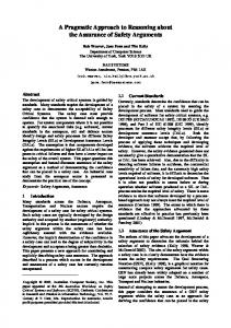
Fig. 1. An example for a complex robot system: the new DLR Two-HandArm-Torso (THAT) with 43 DOF. This system is built from two DLR-LBR-III arms with 7 DOF each, two DLR-Hand-II with 13 DOF each [1] and a torso with 3 DOF.
computing power of commodity systems together with their fast communication links and high-speed buses to the robot components allows for a completely new view on the system architecture of a robot system. This also led to the insight that a mere redesign of the old robot control software was not an adequate solution but that a completely new software concept which makes full use of modern hardware possibilities was necessary. Another important point with strong influence on the requirements for a new software concept is the fact, that a complex robot system is developed by a heterogeneous team of researchers from various fields. This implies that the software concept has to support the specific tools from the different fields and should allow to work independently on different components, but still remains simple and easy to use. Finally, for building complex systems it is highly advantageous that the software concept supports rapid prototyping to allow an iterative development process. In the last years a number of software concepts and frameworks have been proposed to address these challenges of complex robotic systems. Prominent representatives are ORCA [4], MARIE [5], MIRO [6], Player [7], OROCOS [8] and MCA [9]. They are all based on the idea, that a complex robotic system should be composed from interacting modules
3741
or components in the sense of the component based software engineering approach [10] with all its benefits as flexibility, code reuse or decoupling of the development flow in a team. To allow the components to be distributed on a network of heterogeneous computers all approaches also provide tools for simplifying and standardizing communication. These concepts were successfully used in applications, where realtime constraints are relatively soft, e.g. in the field of mobile robotics. But the current implementation of these concepts have not shown that they can easily reach realtime rates above some 100Hz in complex applications with high numbers of DOFs. This is significantly slower than the high rates of 1kHz to some 10kHz with hard realtime constraints needed for mechatronical systems we are working on. Therefore we present in this paper the “agile Robot Development” (aRD) concept, a flexible, pragmatic and distributed software concept especially designed to support the development of complex mechatronic and robotic systems. It gives easy access to scalable computing performance (even in hard realtime) and is based on the abstract view on a robotic system as being a decentral net of calculation blocks and communication links. The paper is organized as follows. First we give a more detailed problem analysis and list of requirements. In the next section we introduce our aRD concept that meets the identified requirements and describe its current implementation. Then, we present performance examples and first applications. Finally, we conclude with future development directions. II. D ESIGN C ONSIDERATIONS The design of a software concept is heavily influenced by the computing hardware available for implementing it on. In robotics in addition it heavily depends on the mechatronic architecture, that is the details of the mechanics, electronics and control. A. State of the Art First we take a look at the state of the art of mechatronics and computing hardware. 1) Mechatronics: Here we present some features of the mechatronic architecture of robots we are currently working with or which are just going to be developed in our institute. • Single robotic components, e.g. the DLR-Hand-II, have 13 DOF and more than 100 sensors (position, forcetorque, temperature, ...). The next generation with 40 DOF for an integrated hand-arm-system is in work. • Complex compound robot systems, e.g. the DLR TwoHand-Arm-Torso (THAT) system, have more than 43 DOF and about 100 DOF in the next generation. • Decentral electronics near the joints for the conversion of sensor signals and actuator commands allows the use of digital serial buses in the robots. • Fast buses to the robots with bandwith of 4MBit up to 1GBit allow for high communication rates (e.g. 10kByte of data at a rate of 10kHz)
Rates of up to 3kHz are used for controlling a single component (joint controller) but also for running sophisticated controllers for all DOF of a compound system as needed for gravitation compensation or impedance control [11]. The rate will reach 10kHz in the near future. The conclusion one can draw from these mechatronic features is, that despite the high complexity due to the high number of DOF and sensors and the high control rates for sophisticated controllers, the high-speed buse still allow for full flexibility in connecting the robots to the computing hardware. 2) Computer Hardware: The dramatic growth of performance in computing hardware makes it possible to use commodity systems even for running complex algorithms in hard realtime. Moreover the use of standard PC components makes it also easy and cheap to participate on future developments. Here we summarize important features of actual PC hardware. • Clock rate of >3GHz. • Multi-Core and Multi-CPU (e.g. Quad-Dualcore-Opteron with 54GFLOPS [12]) systems are standard. • A Cluster with 40 CPU-Cores fits into a small rack (e.g. 30cm x 45cm x 75cm for the Dell PowerEdge 1855). • Performance growth is still exponential with a doubling every 18 month. • Fast communication with low delay is cheap and easy to handle, e.g. for 1GBit ethernet transfer of a 1.5kByte packet takes 15µs. • Flexible communication infrastructure by switched ethernet or a multitude of decoupled point-to-point links (by using multiport adapters 20 ethernet ports in one PC are easy to do). 3) Conclusion: The currently available computing power of commodity systems together with their fast communication links and the high-speed buses connecting the robot components allows to build flexible, distributed computing architectures with scalable computing performance even if hard realtime is required. This offers the possibility to decouple the overall system architecture from the hardware details and to take a functional view on a robot system. An appropriate software concept has to provide both tools for designing this functional view and to mechanisms to map this functional design onto the actual computating and robot hardware. •
B. Functional View To find a good definition of a functional view we start by giving an overview of a typical robot system (see Fig. 2). Such a system consists of a number of robot components connected to a realtime target running the controller loops. Applications for user interaction (e.g. 3D-viewer, GUI) and higler level intelligence (e.g. vision system, trajectory planning) are implemented on a network of non-realtime computers. Those applications can communicate with the realtime target and also possibly have a link to a remote command station, coupled by a WAN or the internet.
3742
Fig. 2. Overview of the system architecture and computing hardware of a complex robot system. A number of robot components are connected to a realtime target running the control loops. Applications for user interaction and higher-level intelligence are executed on a network of non-realtime computers and communicate with the realtime target. In addition there is a development host and a host for low-level monitoring and configuration.
Additional hosts run tools for development (edit-compiledebug) and tools that allow for monitoring and profiling of the different parts of the system during runtime. Leaving the details of the computer architecture aside and refining the structure of the functional modules one ends up with a scheme as in Fig. 3. All of the functionality of the system is now represented by blocks running in realtime or non-realtime. They perform calculations and communicate with each other. Typically the granularity of the realtime part is finer, as each block usually performs only a small amount of deterministic calculation. On the other hand, blocks in the non-realtime part represent more monolithic applications and can perform elaborate algorithms on complex internal representations. It is therefore straightforward to see a robot system as a decentral net of calculation blocks and communication links, in this way defining the functional view on the system. This abstraction not only helps in designing the architecture of a robot system, but also paves the way for a componentbased software engineering approach [10] if supported by the software concept. The component-based approach is particularly well suited as a complex robot system is developed by a team of researchers. If in addition the concept allows changing the structure of the net in a simple and flexible way, rapid prototyping is also naturally supported. Besides the wish for a simple and flexible software concept, one would pragmatically like to keep the implementation from becoming too complicated. What is following are the more detailed design considerations and requirements of the net of communicating blocks taking into account all of the above discussed issues. 1) Equality of Blocks: All blocks are euqal in the sense, that they all can be sources and sinks for data and there is no
distinction in client or server blocks. Such a distinction would be less general and unnatural for most blocks, e.g. a controller block. Also the connection scheme is arbitrary. A block’s output port can be connected to any other block’s input ports, as long as the data formats match. 2) Execution Order: Each block is an execution entity, e.g. a process or thread, and can have its own priority. This allows to schedule the available processing time between the blocks and implicitly defines the execution order. In practice it is often more efficient and simpler to aggregate blocks into groups, where each group is an execution entity and iterates through its blocks. A block can be executed periodically with its own inherent rate or be triggered by new data arriving at its input port. The latter variant gives the flexibility to implement systems with very efficient use of execution time but implies the danger of deadlocks and needs delicate priority adjustment. Especially for blocks running in hard realtime (e.g. controllers) and having robot hardware connected to them it is important to be synchronized. This means, that in a group of synchronized blocks the execution order is deterministic. Blocks in a synchronization group still can run at different rates (multirate), but all rates have to be integer multiples of the fastest rate, the so called base rate, of the group. An example for an asynchronous block would be a viewer block, having its own refresh rate. 3) Data Flow: The data format of each port of each block can be different, but is static during runtime. This simplifies the implementation of a block, but also means, that a block is less than an object or a component, where different methods with different parameters and return values can be called. Nevertheless, this restriction is convenient for robotic system as the static robot hardware (e.g. always the same number of sensor values) implies the static data format for most of the blocks. Also the block’s connection scheme is static at runtime. This design decision dramatically simplifies the implementation, not only of the single block but of the mechanisms for configuring the overall system. Instead of allowing to dynamically change the connection scheme it is possible to disable and enable blocks through input ports, where a disabled block does not consume computation time. Again, this is convenient for robotic systems. A typical task, where dynamic re-wiring seems to be necessary, as e.g. the switching between different controllers, can be almost always solved by statically connecting all alternatives (usually only some ten) and activating exactly one of them by disabling and enabling. All communication in the net of blocks is unbuffered. In combination with a non blocking sending of data through a block’s output port this allows for a simple way, conceptually and with regard to implementation, to connect blocks running at different rates. The receiving block simply reads the last sent data, regardless if its rate is faster (reading the same data multiple times) or slower (reading only every n-th data). If a more specific rate transition is needed, one can simply
3743
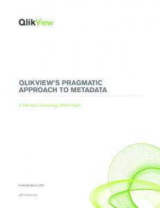
3. Functional view on a complex robot system as a net of calculation blocks and communication links. Starting from a system overview like in Fig. 2 one naturally ends up with this functional view by leaving aside the details of the computing hardware and refining the structure of the functional modules. The system shown here is the DLR Robutler [3] consisting of an arm-hand system mounted on a mobile platform and equipped with a stereo vision system. There is a realtime and a non-realtime part. In the former the granularity of the blocks is usually finer and the blocks represent a hierarchy of different controllers for each robot component (WC=wheel control, MC = mobile control, JC=joint control, AC=arm control, ...) which are connected via devicedriver blocks (dev) to the hardware and run with different rates (0.3ms up to 6ms). In addition there are blocks for computing the inverse kinematics (invkin) or interpolation (ipol) or blocks that control the sequence of execution (SC) getting commands from higher-level blocks. In the non-realtime part the blocks are typically more monolithic applications like a 3D-viewer or GUI for user interaction or a vision system and path planner in combination with an execution control block (EC) for higher-level intelligence.
insert an additional block between the communication partners running at the higher rate and implementing an user defined interpolation scheme. A block sends data by pushing it through its output port to the input ports it is connected to. To keep the design simple, there are no pull or send-with-reply operations, which can nevertheless be easily built on top of the push operation. A further essential requirement for flexible network layout is a mechanism for distributing a block’s output to several receiving input ports. C. System Handling After having specified the properties of the net of blocks and links, the following considerations address the handling and development of such a system. 1) Development Tools: For complex systems consisting of a large number of blocks and links between them a graphical development tool, which allows to organize the net of blocks in a hierarchy of meta-blocks is almost essential. The possibility for rapid prototyping was one of the main design aspects of the overall software concept. This should be supplemented by having a quick edit-compile-debug cycle. Tools for monitoring and visualization of the data flow are also important for getting an insight into the runtime behavior of a complex net of blocks and for finding bugs. A complex full-system-debugging tool is not easily feasable. But taking together the flexibility in re-wiring the blocks, the tools for visualization and the quick turnaround cycles most of the debugging can be done without such a tool. Instead developers can use, so to say, a variant of the classical printf debugging adapted to systems with a decentral data flow.
Furthermore a module for simulation of the dynamics of the robot components is desirable, because it allows to decouple the development of the software from that of the hardware. In principle the same system can be used as a simulator when replacing the real robot components by a simulation of the robot dynamics. Depending on the quality of the model of the robot dynamics the simulator can resemble the behavior and timing of the real system very accurately. This stems from the facts that the other parts of the system are unchanged and that the simulation can also be run on the realtime target, due to scalability of computing power. For a team of developers a simulator is especially worthwhile as it allows to parallize the development flow by simply running more than one simulator. Additionally, together with the flexibility of the software concept specific testbeds for parts of the system can be easily built. The development tools should also assist the mapping of the abstract net of blocks onto a concrete network of computers. 2) Interfaces: The aRD concept only provides a flexible communication infrastructure for the net of blocks. The functionality, however, is implemented in the blocks. Therefore it is very important that the interface for writing a block and integrating it in the net’s communication structure should be open to arbitrary programming languages. This is especially important as in robotics the blocks are contributed by a team of expert from different fields each requiring its specific tools and languages. The interface for writing a block should also be simple, as researchers are experts in their field but not necessarily software experts and are not willing to invest much time to understand sophisticated software frameworks.
3744
3) Configuration, Startup and Shutdown: The description of the configuration of a system consists of two parts. First, the structure of the net of blocks has to be described. Second, the mapping of this net to the actual computing hardware has to be specified, to describe which block runs on which computer and communicates over which links. At runtime the system is a decentral net of communicating blocks distributed over a network of computers. The software concept has to provide mechanisms to allow for a central startup from one console and a coordinated shutdown. III. I MPLEMENTATION The two main guidelines for the implementation of the aRD concept were to realize the principle of a decentral net of calculation blocks and communication links in a pure but simple way and to keep the implementation effort as little as possible by pragmatically relying on the functionality of the operating systems and using any tool, open source or commercial, which was appropriate. The current implementation of the aRD concept consists of aRDnet, a simple software suite developed at our institute and a toolchain based on Matlab/Simulink/RTW [13] and RTLab [14]. As operating systems (OS) we use QNX Neutrino [15], a POSIX-compliant microkernel realtime OS, for the realtime target, Linux for the non realtime computers and Windows XP for the development hosts. A. Matlab/Simulink Toolchain Matlab/Simulink is the quasi-standard tool for simulation of robot dynamics and controller design. A Simulink model resembles the functional view on a system as being a net of communicating blocks. Each block can have an arbitrary number of input and output ports of usually real valued vectors as well as an internal state vector. Basically, during model execution the blocks are sequentially called in each simulation step to compute the new state and output from the actual state and input. Simulink’s formidable graphical editor allows for a hierarchical organization of groups of blocks in so called subsystems. The success of Simulink is also founded in its rich library of blocks, including not only calculation blocks but also blocks for data visualization and user interaction. In addition due to its open architecture a multitude of third-party toolboxes for different fields of application are available. With RTW (Realtime Workshop) it is possible to automatically generate from a Simulink model executables running on a realtime target. To assure deterministic runtime behavior RTW allows only a subset of blocks which implement deterministic calculations and do not demand a console for user interaction. If some of the blocks implement communication to I/O-device cards with real hardware connected, such a system is known as a hardware-in-the-loop (HIL) environment. By using RTLab even a semi-automatic parallelization of the Simulink model to run on multiple CPUs or even distributed computing resources is feasible. The developer can easily specify which parts of the model should run on which CPU
or computer. The Simulink model has only to be organized in a way, that the subsystems at the highest level resemble the desired model partition. All code for communication and synchronization of blocks running on different CPUs is automatically integrated by RTLab. Having semi-automatic rather then automatic parallization does not impose a severe restriction for robotic systems as the modular structure of the robot hardware usually induces a natural partition of the model. Due to its distributed character the important issues of inspection of and interaction with the model during runtime have to be addressed differently by RTLab than it is done by other HIL development enviroments like xPC Target [13] or dSPACE [16]. When specifying the partition of the model, one of the subsystems can be marked as the ”console” subsystem. This subsystem is not loaded to the realtime target, but instead a new model is generated from it which is run in a standard Matlab/Simulink enviroment on the host computer during model execution. The code for communication with the realtime part of the model is again automatically included by RTLab. This communication, however, is done assynchronously to not defer the model’s realtime behavior. In the console subsystem the complete Simulink library, e.g. scopes and switches, and even toolboxes, e.g. the Virtual Reality Toolbox for 3D-visualization, can be used. In addition RTLab also allows to change the parameters of all blocks of the model during runtime by means of a parameter browser. With respect to extensibility it is important that Simulink is an open tool. It has a simple and well documented interface of call-back functions for implementing own blocks, so called “S-function blocks”. A multitude of programming languages including Matlab and C are supported. To simplify the implementation of standard blocks even further, the aRD concept provides a wrapper to Simulink’s S-function interface. Thus the developer has only to write an init function to be called at the initialization of the model to specify the number and dimensions of the block’s ports. Furthermore a calc function is needed which is called at each simulation step to perform the actual calculation. The execution of all blocks in a model is synchronized (except for blocks from the console subsystem), even when they are distributed over several computers. Simulink also provides multirate processing running each group of blocks with the same rate in a separate thread. In addition the enabling/disabling and triggering of subsystems is supported to control the execution of its blocks by means of input from other blocks. B. aRDnet Besides the blocks that are part of the Simulink model and which implement mainly controller related functionality, important parts of the net are made of standalone blocks. A standalone block is an individual process running an arbitrary executable which, as part of the net, sends and receives data packets.
3745
4. Implementaion of the net of communicating blocks (see Fig. 3) of a complex robot system on a concrete computing hardware using the aRD software concept. The QNX realtime target consists of two PCs with multiple CPUs and the non-realtime blocks are executed on three PCs running Linux. The controllers are implemented in a Simulink model consisting of two subsystems (ellipses with white insets) each running on a separate CPU and communicating by code automatically generated by RTLab. To connect standalone blocks, like the device-driver blocks or blocks with nondeterministic computation time, like some inverse-kinematics algorithms, and blocks in the Simulink model the aRDnet suite provides Simulink stub blocks. Communication between standalone blocks running on different computers is realized by an ardnetbridge consisting of an ardnet block (circles with ”an”) on each side. The system can be run as a simulator by replacing the real robot hardware by a second PC with multiple CPUs or even a cluster of PCs running blocks for simulating the robot dynamics and the interaction with the enviroument.
Typical examples for such blocks running in the realtime part are I/O-blocks that implement the device drivers for communication with the connected robots or other hardware. Another example are non-deterministic calculation blocks which are asynchronously coupled to the Simulink model, for instance an inverse kinematics wich uses some kind of iterative minimization algorithm. Also, computationally demanding blocks like the simulation of the dynamical interaction of a robot with its environment are possible. In the non-realtime part standalone blocks are usually applications for user interaction (GUI) and higher level intelligence (vision system, trajectory planning). Each block can have multiple input and output ports, but each output port is connected to exactly one input port of an arbitrary block with matching data formats. aRDnet is laid out as a simple software suite that supports and standardizes the communication between blocks. The suite was developed at our institute and consists of three parts. First, a library for easy implementation of a block’s input and output ports is provided. Second, the ardnet executable realizes communication between blocks running on different computers. Finally, a template for a Simulink stub block has been introduced, which allows for easy communication between standalone blocks and blocks in the Simulink model. In its current implementation the aRDnet suite supports blocks running on computers with QNX, VxWorks and Linux. In the near future we are planning to also support Windows. 1) aRDnet Library: The aRDnet library provides a native C/C++-interface. Based on this interfaces to other programming languages can also be easily built as most languages allow to be extended by C-code. For Matlab and Python we have already realized such interfaces.
The simple interface consists of only five functions: •
•
•
create and init for creating and initializing the input and output ports of a block. Details of the created properties of the port can be configured by special command line arguments provided at startup to the block’s process. This is similar to the mechanism the X-Window system library Xlib uses to implement standard command line arguments for all X-clients (e.g. the ”-display” argument). send for non-blocking sending of a data packet through an output port. As all communication is unbuffered the last packet sent gets directly transported to the connected input port of the receiving block. rec and tryrec for blocking and non-blocking receiving of data over an input port. The blocking version waits until a new packet arrives and returns this data. In this way the execution of the block can be triggered on arrival of new data. In contrast, the non-blocking version returns immediately with the data that has arrived last.
This set of functions for sending and receiving implements a pushing semantics for data transport. The size and format of a data packet can be different for each port of each block, but is static and defined at compile-time. As only the blocks which are connected to each other have to know about the data format, this can easily be specified, e.g. in a common include file. The connection scheme of the block’s ports is determined by providing command line options at startup of each block’s executable. For each port of a block a separate name is specified. Connections are simply determined by matching port names for input and output and as each output port can only drive exactly one input port, every connected pair of ports has
3746
to have a unique name. The current implementation of the aRDnet library achieves all of the above by only a thin layer of abstraction over the functionality of the underlying operating systems. Basically only the POSIX ”named shared memory”, semaphores and mutexes are used. 2) ardnet executable: The ardnet executable serves three important purposes with regard to the communication abilities in the net of blocks. Being also based on the aRDnet library it can be seen as a block,however, with special features. First, ardnet realizes the communication between two blocks on different computers by running a corresponding pair of ardnet processes as a network bridge. For this purpose ardnet has built-in functionality for transmission of data over the network providing a ”virtual wire” between the two communicating blocks. Communication is carried out unbuffered, i.e., if the rate of the sender is higher than the rate ardnet can transmit packets may be dropped. The packets sent, however, are always the most recent ones. In the current implementation ardnet uses bare UDP sockets but it can easily and transparently be extended to any other transportation protocol, e.g. EtherCAT, or even media, e.g. InfiniBand. To address the problem of blocks running distributed even on heterogenous computers (with differing CPU families, operating systems and compiler versions) the aRDnet suite defines compatible basic data types. In this way, the aRDnet library assures the right representation on both sides because the data packet is assembled from these basic types. Furthermore, a detailed control of quality of service (QoS) is possible by choosing different network connections, e.g. pointo-point or switched ethernet, using separate network stacks (a particular feature of the QNX microkernel architecture) and finally by adjusting process priorities. This way we have been able to achieve realtime communication over four ports with a rate of 1kHz on each line (for details see IV). The second purpose ardnet serves is to provide a port multiplier block. Therefore ardnet can be configured to have one input but multiple output ports. Each data packet arriving at the input is distributed onto all output ports. Finally, ardnet can be used to reduce the rate at which data is sent between two blocks. This is done by inserting an ardnet block into their communication line. The ardnet block can then be configured either by setting a maximum sending rate or by forwarding only every n-th incoming data packet. All these different configurations and parameters can be controlled via command line options at startup. 3) Simulink stub: To connect standalone blocks to blocks implemented in the Simulink part of the net the aRDnet suite provides a template S-function code. This easily allows to generate a stub block for Simulink representing the actual block. The developer has only to implement three functions. One specifies the stub block’s layout (number and dimensions of in- and outports). The other two functions translate the data packets being sent by the standalone block through its output
ports to the outport lines of the stub block and, in the other direction, translate the data at the stub’s inport lines to the data packets received at the standalone block input ports. The connection between the standalone block and its stub is implemented with the help of the standard aRDnet library mechanisms. This allows for a seamless integration of the two parts of the net. C. Startup and Shutdown Starting the decentral net of standalone blocks distributed over a network of computers is done by using a hierarchy of shell scripts very similar to the way a Unix system starts up. A master script calls subscripts for setting up particular system parts (e.g. the driver blocks for the robot hardware). To allow for the startup of a distributed system from a single central command station the aRDnet suite provides the ardstart command for starting up programs and scripts on a remote computer. In addition ardstart does bookkeeping of what has been started where. This information is needed for a coordinated shutdown of the whole system or only specific subsystems and is exploited by the ardkill command of the aRDnet suite. The hierarchy of shell scripts together with the Simulink models give a complete description of the system configuration. As the structure of the shell scripts is simple, they can e.g. easily be generated automatically from a graphical representation of the net. IV. A PPLICATIONS
AND
P ERFORMANCE
In this section we present some performance measurements and first applications which are based on the above implementation of the aRD concept. If not otherwise mentioned all measurements were performed on a PC with Pentium 4, 3GHz. • aRDnet Performance: The time it takes in worst case to transfer a data packet of 1kByte between two standalone blocks running on the QNX realtime target is measured, including everything from calling the send routine until the rec routine of the receiving block returns. For two blocks on the same computer the transfer time is 7µs. For two blocks on different computers connected by an ardnet bridge over a 1Gbit ethernet point-to-point connection the time is 90µs (and 60µs on average). • High Rate: In a HIL setup a simple Simulink model reads analog values from an I/O-card and records them to the harddisk. At a rate of 30kHz the system introduces only little overhead (e.g. due to scheduling) of less then 10% of cpu-time. • Multirate: A robot arm is connected to a VxWorks computer, which sends the sensor and actuator data at a rate of 1kHz via an ardnet bridge to a QNX realtime target running a Simulink model with a controller also at a rate of 1kHz. The very same Simulink model contains a subsystemm running at rate of 10kHz for reading in analog values from a sensor via an I/O-card. • Deterministic Execution and Jitter: In the very same system as above, we could increase the average cpu load
3747
the functional view of a net of communicating blocks is well-suited to complex robotic systems, • one can make use of the power of modern commodity computer hardware, • only tools for supporting and standardizing communication are provided, but • users can develop their own standards and interfaces for the data on demand, • one can do a prototypical implementation of new functionality first and easily integrate it after it proved to be of general use, • it has a simple and small implementation, and because • tools and functionality of operating systems have been chosen pragmatically. At our institute almost all projects are currently being ported to the aRD concept. These projects range from teststands of new robot joints over medical and space robotics to humanoid manipulation experiments. First examples already show that this unifying approach promises synergetic benefit between these formerly distinct areas. •
Fig. 5. Preliminary study for bimanual manipulation. The system consists of a DLR-LBR-II and DLR-LBR-III arm and two DLR-Hand-II robot components. The task was to grasp and empty a basket. With this setup the control concepts for the new DLR-Two-Hand-Arm-Torso system (THAT) and the aRD software concept have been succefully tested.
•
•
of the Simulink model up to a level of 90% before loosing simulation steps, even while running debug and profiling tools over a second network connection. This implies that system jitter, even in case of the 1kHz network communication rate via ardnet, is significantly smaller than 100µs. Two-Hand-Arm Setup (see Fig. 5): For a preliminary study for the new DLR-THAT system two arms and hands are connected to four VxWorks computers each communicating at a rate of 1kHz via a point-to-point ardnet bridge with the QNX realtime target. All 40 DOF could be controlled at a rate of 1kHz by one Simulink model. THAT-Simulator: For building a simulator for the THAT system we substituted the robot hardware by simulation blocks and extended the system configuration by visualization and user interaction blocks (see Fig. 1 and Fig. 4). The former blocks were running on additional CPUs of the realtime target, whereas the user frontend was executed on a network of non-realtime computers. V. C ONCLUSION
In our robot system configurations at DLR the aRD concept has proven successful and to be agile in at least two senses. First it supports the development of agile robots, i.e. robots that are dynamic, responsive and intelligent, by giving easy access to scalable computing power even in hard realtime and allowing for easy integration of non-realtime modules implementing higher level intelligence functionality. Second, it supports an agile flow of development, meaning flexible, adaptive and rapid, in the spirit of the ’Agile Software Development’ methodology [17], [18] that is especially suited to small teams of experts. This could be achieved by the simple yet general functional view on a robotic system as a net of communicating blocks in combination with an open and easily usable implementation of this view. In short, the aRD concept has turned out successful, because
R EFERENCES [1] G. Hirzinger, N. Sporer, M. Schedl, J. Butterfass, and M. Grebenstein, “Torque-controlled lightweight arms and articulated hands: Do we reach technological limits now?” The International Journal of Robotics and Research, vol. 23, no. 4–5, 2004. [2] C. Preusche, D. Reintsema, K. Landzettel, and G. Hirzinger, “Robotics Component Verification on ISS ROKVISS – Preliminary Results for Telepresence,” in Proc. IEEE/RSJ International Conference on Intelligent Robots and Systems (IROS) 2006, accepted for publication. [3] U. Hillenbrand, B. Brunner, C. Borst, and G. Hirzinger, “The Robutler: a vision-controlled hand-arm system for manipulating bottles and glasses,” in Proc. 35th International Symposium on Robotics, 2004. [4] A. Brooks, T. Kaupp, A. Makarenko, A. Oreb¨ack, and S. Williams, “Towards component-based robotics,” in Proceedings IEEE/RSJ International Conference on Intelligent Robots and Systems (IROS 2005), 2005. [5] C. Cote et al., “Code reusability tools for programming mobile robots,” in Proceedings IEEE/RSJ International Conference on Intelligent Robots and Systems, 2004, pp. 1820–1825. [6] H. Utz, S. Sablatng, S. Enderle, and G. K. Kraetzschmar, “Miro – middleware for mobile robot applications,” in IEEE Transactions on Robotics and Automation, Special Issue on Object-Oriented Distributed Control Architectures, 2002. [7] R. T. Vaughan, B. Gerkey, and A. Howard, “On device abstractions for portable, resuable robot code,” in Proceedings of the IEEE/RSJ International Conference on Intelligent Robot Systems (IROS 2003), 2003, pp. 2121–2427. [8] Orocos. [Online]. Available: http://www.orocos.org [9] Mca2. [Online]. Available: http://www.mca2.org [10] G. T. Heineman and W. T. Council, Component-based Software Engineering. Putting the Pieces Together. Reading, MA: Addison-Wesley, 2001. [11] A. Albu-Sch¨affer, C. Ott, and G. Hirzinger, “A unified passivity based control framework for position, torque and impedance control of flexible joint robots,” in Int. Symposium on Robotics Research 2005, 2005. [12] AMD Linpack Benchmark. [Online]. Available: http://www.amd.com/de-de/Processors/ProductInformation [13] The MathWorks. [Online]. Available: http://www.mathworks.com/ [14] OpalRT. [Online]. Available: http://www.opal-rt.com/ [15] QNX Software Systems. [Online]. Available: http://www.qnx.com/ [16] dSPACE. [Online]. Available: http://www.dspace.de/ [17] (2001) The Manifesto for Agile Software Development. [Online]. Available: http://agilemanifesto.org/ [18] A. Cockburn, Agile Software Development. Reading, MA: AddisonWesley, 2001.
3748