Int. J. Embedded Systems, Vol. 3, Nos. 1/2, 2007
83
Algorithms for low power hardware synthesis from Concurrent Action Oriented Specifications (CAOS) Gaurav Singh* and Sandeep K. Shukla FERMAT Lab, Electrical and Computer Engineering, Virginia Tech, Blacksburg, VA, USA E-mail:
[email protected] E-mail:
[email protected] *Corresponding author Abstract: Behavioural synthesis has received considerable attention recently and new action-oriented hardware specification formalisms have been proposed. We call such formalisms Concurrent Action Oriented Specifications (CAOS). CAOS models have low granularity concurrent atomic action descriptions with a semantics similar to Dijkstra’s guarded command language. Such models have been shown to generate efficient hardware designs, and the importance of making such CAOS-based synthesis process power-aware cannot be undervalued. In this paper, we formulate the problems of power-optimal synthesis for CAOS, discuss several heuristics and show some numerical examples illustrating the use of such heuristics during CAOS-based synthesis. Keywords: behavioural synthesis; concurrent action-based specifications; low-power design; peak power; switching power. Reference to this paper should be made as follows: Singh, G. and Shukla, S.K. (2007) ‘Algorithms for low power hardware synthesis from Concurrent Action Oriented Specifications (CAOS)’, Int. J. Embedded Systems, Vol. 3, Nos. 1/2, pp.83–92. Biographical notes: Gaurav Singh is a PhD student at Virginia Polytechnic Institute and State University, Blacksburg. His research interests include low-power synthesis, dynamic power management, system level design for embedded systems and software design. His current work involves developing algorithms/strategies for low-power behavioural synthesis of hardware designs. He is a student member of IEEE. Sandeep K. Shukla is an Assistant Professor of Computer Engineering with the Virginia Polytechnic Institute and State University, Blacksburg. He is a founder and Deputy Director of the Center for Embedded Systems for Critical Applications (CESCA) and Director of the FERMAT Laboratory, Virginia Tech. He has authored/co-authored over 100 papers in journals, books and Conference Proceedings. His research focuses on system-level design languages, formal methods, formal specification languages, probabilistic modelling and model checking, dynamic power management, application of stochastic models and model analysis tools for fault-tolerant system design and reliability measurement of fault-tolerant systems. He has Chaired a number of international conferences and workshops and is also a senior member of IEEE.
1
Introduction
The pervasive use of complex embedded and portable systems having limited battery-life makes power management essential in hardware designs. Various power-efficient design techniques are used in such designs in order to keep the power dissipation within acceptable limits. The average power dissipation in an integrated circuit consists of the following components: •
dynamic power
•
leakage power
•
short circuit power (Raghunathan et al., 1998).
Copyright © 2007 Inderscience Enterprises Ltd.
Dynamic power is related to switching activity and in order to reduce this component of power during behavioural synthesis we need to minimise the switching activities in the target hardware. Leakage power is the static component of the power dissipation and can be reduced by using the technique of power-gating during synthesis. However, insertion of power-gates might increase latency and therefore correct grouping of circuit elements and a predictive scheme for triggering power-gating are needed. The third component of power is the short circuit power, which is reducible by reducing signal transition times, and this is the hardest component to reduce through synthesis-time optimisations.
84
G. Singh and S.K. Shukla
In this paper, we consider power reduction techniques that can be applied during behavioural synthesis of hardware from high level specifications. Most existing behavioural synthesis techniques (e.g., Chang and Pedram, 1999; Lakshminarayana et al., 1998) which optimise for low-power hardware take the input specification of the hardware at an abstraction level which is slightly higher than the RTL level, namely Control Data-Flow Graphs (CDFGs), or hierarchical variants of those, such as Multi-Threaded Graph models (MTGs) (Theon and Catthoor, 2000) or Hierarchical Task Graphs (HTGs) (Gupta et al., 2004). These models already sequentialise parts of the computation in the form of computation threads. During behavioural synthesis, scheduling, allocation, and binding steps are solved as combinatorial problems on these graph-based data-flow models. In this paper, we consider in some sense a slightly higher abstraction level, where the computation of the target hardware is described using concurrent atomic actions, similar to Bluespec (Arvind et al., 2004). We call this specification model CAOS or Concurrent Action Oriented Specification. Bluespec is our prime example of such a specification language and formalism. We discuss here a class of heuristics targeting the reduction of the peak and average dynamic power in the scheduling and allocation phases of the concurrent action-based synthesis process. Our approach is based on first creating a schedule based on highest possible parallelism among the actions by analysing the conflict graph as done in Arvind et al. (2004). Our heuristics create alternative schedules which will reduce power by reducing the parallelism in some cases, thereby reducing the peak power and in some cases, by cleverly allowing resource sharing in such a way, that the switching power can be reduced. It can be easily shown that all the optimisation problems germane in the low-power version of the schedule are NP-hard problems. Therefore, the figures of merit for the heuristics we provide are measured in terms of power savings with respect to the most concurrent schedules. One important aspect of the re-scheduling approach is that the actions that are re-scheduled may lead to an implementation of the hardware that is not clock-cycle equivalent to the original one, except at certain predefined synchronisation points. Such equivalences are quite common in hardware design when re-timing and other optimisations are done. In other words, the hardware generated by these heuristics is functionally equivalent to the one that does not consider power optimisation and allows maximal parallelism. We call the hardware implementation that uses maximal concurrency the ‘reference design’. This might also mean that the latency of certain outputs in the synthesised result may suffer and the goal is to minimise such penalties in latency. In most cases however, our optimisations will reduce area, thereby providing solutions which are better in at least two design parameters. The rest of this paper is organised as follows. Section 2 briefly discusses some related work on low-power
behavioural synthesis. Section 3 presents a description of the concurrent action-based synthesis. In Section 4, we formalise the problem of power-optimal hardware synthesis from action-oriented hardware specification and discuss the complexity of the peak and dynamic power optimisation problems to provide a justification of the heuristic approaches. The scheduling and re-scheduling heuristics and their analysis are provided in Section 5. Section 6 works out some numerical examples to illustrate the heuristic algorithms. And in Section 7 we conclude by discussing ongoing and future work.
2
Related work
Previous approaches on power minimisation during behavioural synthesis are based on CDFG based synthesis. Many power management techniques for high level synthesis have been proposed in the past (Shiue, 2000; Lakshminarayana et al., 1998; Monteiro et al., 1996; Raghunathan et al., 1997). In Shiue (2000), an Integer Linear Programming (ILP) model for peak power minimisation under latency constraints is presented. Lakshminarayana et al. (1998) proposes a power management technique targeted towards high-level synthesis of data-dominated behavioural descriptions. The technique limits the amount of spurious computations in various functional units of the synthesised design. In Monteiro et al. (1996), a scheduling algorithm which aims to maximise the idle times for functional units is presented. Raghunathan et al. (1997) proposes a controller re-specification technique based on re-designing the controller logic to reduce the activity in the components of the datapath. A comprehensive high level synthesis system for reducing power consumption in control-flow intensive as well as data-dominated circuits is presented in Khouri et al. (1999). In Raghunathan et al. (2001), the authors address the issue of managing transient power consumption through the choice of appropriate architectures during high-level synthesis. Mohanty and Ranganathan (2004) proposes a framework for simultaneous reduction of energy and transient power components during behavioural synthesis.
3
Concurrent action-based synthesis
In the CAOS formalism, the behaviour of the design is described using a collection of guarded atomic actions at a level of abstraction higher than RTL. Each action consists of an associated condition (called the guard of that particular action) and a body. An action executes only when its associated guard is true and the body of an action operates on the state of the system. The state can be explicitly defined by the designer in the high-level description of the system or, in other cases, can be inferred from that description. In the Bluespec model of computation, there is no need to infer the state because the designer explicitly instantiates all the state elements
Algorithms for low power hardware synthesis of the system (like registers, FIFOs, memories etc.). This model then undergoes synthesis to generate the RTL code (Arvind et al., 2004). An action in the concurrent action-based description of a design can be written as, Action A : g(s) → s = b(s, i). Here, g(s) is the guard associated with action A and s = b(s, i) is the body of that action. s represents the state of the system. b(s) computes the next state of the system using the current state s and the current input i. The actions are atomic in the sense that either all the computations corresponding to the body of an action finish successfully, or none of them executes. Two actions are said to be in conflict with each other if they update one or more of the same state elements. Multiple actions can execute concurrently as long as they do not conflict, thus exploiting maximum parallelism present in the design. The system execution stops when no guard evaluates to True. Example: Below is an example of an action-oriented description of a Longest Prefix Match (LPM) module (Arvind et al., 2004). It takes 32-bit IP addresses, looks up the destination (32-bit data) for each IP address in a table in a memory and returns the destinations. The module is pipelined and the results are returned in the same order as requests. The memory is also pipelined and has a fixed latency of L cycles. One of the possible implementations of a LPM module is in the form of a Circular Pipeline as shown below. Figure 1
Circular pipeline specification of the LPM module design using concurrent actions
In the above example, Action 1 represents the Input stage which takes an IP address IPaddr from fifo1 and a token from the Completion Buffer. It then places a tuple (token, IPaddr[15:0], state0) into fifo2 and enqueues a memory request using the 16 bits of the IP address.
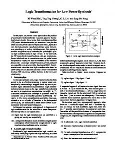
85 Based on the memory response d and the first tuple (token, IPaddr, s) in fifo2, either the Completion (Action 2) or Circulate (Action 3) stage executes. If the lookup is done the Completion stage forwards the tuple containing the memory response d and the token to the Completion Buffer else the Circulate stage places the tuple (token, IPaddr, s + 1) into fifo2 and launches another memory request. In this example, since IP addresses need varying numbers of memory references, each IP address goes around the pipe as many times as the number of needed memory references. This means that the requests finish out of sequence. Thus, tokens from the Completion Buffer are used to make sure that the results arrive in the right order. After the parts of an action corresponding to combinational logic have executed, all the other parts of an action will occur in parallel in order to achieve maximum parallelism. For example, in Action 1 (Input), after IP address and token are fetched (combinational parts), the other two parts of the actions which place a tuple into fifo2 and enqueue a memory request will occur in parallel. Similarly, in the (Action 3 (Circulate)), the portion of the action that places a tuple in fifo2, enqueues a memory request and acknowledges the reading of result will be executed in parallel after the part that dequeues the tuple from fifo2 has executed. This kind of parallelism is quite common in hardware design. However, the use of concurrent actions (multiple actions executing in the same clock cycle) in the above example reflects the additional amount of parallelism that can be exploited through synthesis from the action-oriented specification style. The example illustrates that using action-oriented specifications relieves designers from worrying about global coordination, thus allowing them to focus on the much simpler task of local correctness. Larger examples of similar kind may be found in Kurki-Suonio (1998) and Misra (2001). Hardware synthesis using the concurrent actions can be achieved by implementing each g and b as a combinational logic. Also, a control circuit will be needed that picks up a maximum number of actions (among those having their guards true) to be executed concurrently in each clock cycle. Figure 2 shows the translation from the actions into the hardware. The circuit shown is generated in the concurrent action-based synthesis flow. The guards (g’s) and update functions (b’s) are computed for each action using a combinational circuit. The scheduler is designed to select a maximal subset of applicable actions under the constraint that the outcome of a scheduling step can be explained as atomic firing of actions in some order. The Control Circuit selects the actions to be executed and updates the current state with the resulting values. Thus, there exists an almost direct translation from the action-oriented specification of the design to its hardware.
86
G. Singh and S.K. Shukla
Figure 2
Synthesis from concurrent actions
(corresponding to Input, Complete and Circulate stages) as shown in Figure 1. Definition 4: The weight w of an action is the measure of computational effort of an action. It can be estimated in terms of the number of operations involved in a action. The higher the number of operations in an action, the larger is its weight. Since higher computational effort usually implies more power consumption, w can be used to represent the power consumed by the combinational logic corresponding to the body of an action.
Source: Arvind et al. (2004)
4
Formalisation of the problems
Consider a design and let S denote the set of its state elements. Each state element si ∈ S can be assigned a value depending on its type and a set of values of these state elements denotes the state s of the design. Various possible types of state elements are registers, FIFOs, memories, etc. A state element si is updated in a clock cycle if one or more of the actions updating it are executed in that cycle. Let O denote the set of all the operators that can be operated on the elements of set S. Definition 1: A guard g(s) of an action is a function which maps the set of vectors, each representing the state s of the design, to {0, 1}. In Figure 1, the expressions on the left side of the arrows (→) in each action are the guards of the respective actions describing the LPM module. For example, for Action 2 (Complete) shown in Figure 1, expression, (isLeaf(d = RAM.readResult)) is the guard. It reads a memory response d and checks if the lookup is complete. If the guard evaluates to True, then the action executes, otherwise not. Definition 2: A body b(s) of an action is a set of assignment, conditional or other statements which update various state elements s ⊆ S of the design. If the guard of an action evaluates to be True, then the body of the action is executed. In Figure 1, the part of various actions on the right side of the arrows (→) are the bodies of these actions. In that example, following is the body for Action 2 (Complete): Definition 3: An action a of a design is defined as a 2-tuple < g(s), b(s) >, where g(s) is the guard of the action and b(s) is the body of the action. In the concurrent action-based synthesis flow, the behavioural description of a design is given in terms of various state elements and actions of the design. For example, a Circular pipeline form of the LPM module design can be described using three concurrent actions
The body of Action 1 (Input) of the LPM module, shown in Figure 1, involves four statements. Thus, we can assign a weight of four to this action. Similarly, Action 2 (Complete) and Action 3 (Circulate) can be assigned weights of three and four respectively. Thus, w1 = 4, w2 = 3 and w3 = 4 for the LPM module design. Definition 5: An action ai is said to have a dependency on another action aj if aj updates a state element s ∈ S which is accessed by ai. Let di,j denote a dependency between any two actions ai and aj; that is, di,j denotes that an action ai is dependent on action aj. For example, in the LPM module, Action 2 (Complete) and Action 3 (Circulate) can not execute unless Action 1 (Input) launches a memory request. Thus, it can be said that Action 2 and Action 3 are dependent on Action 1. Definition 6: The value vi of an action ai is the measure of the priority associated with that action. A value can be assigned to an action in various ways depending on the design. One such way is to give a higher value to an action on which large number of other actions are dependent. Definition 7: Two actions ai and aj are said to conflict with each other if both ai and aj update one or more same state elements. In the LPM module example above, both Action 1 (Input) and Action 3 (Circulate) enqueue in fifo2. Thus, they are said to be conflicting with each other. Definition 8: Two guards are said to be mutually exclusive if their conjunction can never evaluate to True. For example, in the LPM module example, guards of Action 2 (Complete) and Action 3 (Circulate) are mutually exclusive, since one is the negation of the other and hence, both can never evaluate to True in the same clock cycle. Definition 9: Synchronisation Points are the points in time during the execution of a design where the values of various state variables should be the same for various possible hardware implementations of that design. These points are defined by the users of the synthesis algorithms and they indicate the points at which the synthesised design will be equivalent to the ‘reference design’.
Algorithms for low power hardware synthesis
87 Let Pswitch denote the total switching power consumed by the design. Now, the switching power minimisation problem can be formalised as,
For the rest of the paper we assume the following: Let A be the set of all the actions of a design. Let wi be the weight of an action ai, where ai ∈ A. Let D be the set of all dependency relationships of a design. Let SP be the set of various pre-defined synchronisation points of a design.
under the following constraints:
4.1 The peak power problem
•
satisfy all dependencies di,j ∈ D between various actions of the design
•
the new schedule of the execution of actions should produce behaviour which is equivalent to the schedule of the ‘reference design’ at all pre-defined synchronisation points sp ∈ SP.
In hardware synthesis from CAOS, a control circuit selects the actions which can be executed in a clock cycle. The number of actions that execute in a particular clock cycle determines the peak power consumed in that cycle. Higher peak power is undesirable due to packaging, cooling and reliability considerations, thus making peak power minimisation an essential part of the low-power synthesis goal. For the ‘reference design’, let G be the maximal set of actions which execute in a particular clock cycle. These will be the actions which have their guards evaluate to True and do not conflict with each other. If two actions, having their guards evaluate to True, are conflicting with each other, then the one with the higher user-defined urgency is chosen to be in G; in case, the two actions have the same urgency, one is chosen arbitrarily. Let fi denote a variable which takes a value 1 if the action ai should be executed in a particular clock cycle to achieve the low peak power goal and 0 otherwise. Now, if Ppeak is the maximum allowable peak power for the design, then for each cycle, the peak power minimisation problem can be formalised as, maximise (∑ vi × fi )
(1)
i∈G
under the following constraints: •
∑
•
satisfy all dependencies di,j ∈ D between various actions of the design
•
The new schedule of the execution of actions should produce behaviour which is equivalent to the schedule of the ‘reference design’ at all pre-defined synchronisation points sp ∈ SP.
i ∈G
( wi × fi ) ≤ Ppeak
4.2 The dynamic power problem As mentioned earlier, dynamic power is a major component of the total power consumption of a design. Consequently, power optimisation techniques targeting the reduction of the dynamic power form an integral part of low-power design strategies. Dynamic power depends on the switching activity in the circuit. Large amount of switching at the inputs of various functional units of the design leads to high dynamic power consumption. Thus, dynamic power can be significantly reduced by reducing the amount of switching that occurs at the inputs of the functional units between different clock cycles.
minimise( Pswitch )
(2)
A few words on the complexity of the above mentioned power optimisation problems are due here. We show that the peak power optimisation problem as well as the dynamic power optimisation problem are NP-Complete.
4.2.1 The peak power problem is NP-complete Here, we sketch the proof of NP-Completeness of the peak power optimisation problem by showing the reduction from the 0/1 Knapsack problem. The 0/1 Knapsack problem (Garey and Johnson, 1979) states that given a set of items, each with a cost and a value, determine if an item should be included in a collection so that the total cost is less than some given cost and the total value is as large as possible. The number of each item is restricted to zero or one. It is known that the 0/1 Knapsack problem is NP-complete. The 0/1 Knapsack problem can be reduced to the peak power optimisation problem as follows. The items in the Knapsack problem can be thought of as the actions of the peak power problem. The cost of each item in the Knapsack problem can correspond to the weight of each action. The total cost can be thought of as the peak power Ppeak. Thus, if a solution to the 0/1 Knapsack problem exists, then the peak power optimisation problem can also be solved and vice versa. Hence, it can be claimed that a solution to the 0/1 Knapsack problem exists if and only if there exists a solution of the peak power optimisation problem. Since the peak power optimisation problem clearly belongs to NP and the 0/1 Knapsack problem (which is NP-Complete) can be reduced to the peak power optimisation problem, this implies that the peak power optimisation problem is also NP-complete (Garey and Johnson, 1979). Thus, no polynomial time algorithm exists for the peak power minimisation problem mentioned above, which justifies the use of heuristic algorithms for the peak power minimisation problem.
4.2.2 The dynamic power problem is NP-complete Now, in order to analyse the complexity of the dynamic power optimisation problem, consider the problem of Directed Hamiltonian Path, which is stated as follows:
88
G. Singh and S.K. Shukla
Given a directed graph G = (V, E) and a function W : E → R which maps each edge in the set E to a real number, find a path that includes every vertex of set V exactly once; that is, find a path p = (v1,v2, ..., vn) containing all the vertices in V such that, vi ≠ vj ∀ vi ∈ V, vj ∈ V, i ≠ j and
∑
n k =1
W (vk , vk +1 ) is minimised.
The Directed Hamiltonian Path problem is NP-Complete (Garey and Johnson, 1979). Now, consider a special case of the dynamic power optimisation problem. Let A′ be a set of actions, f be a functional unit and S be a function which relates a pair of actions to the amount of switching power p consumed due to the switching at the inputs of f when both the actions of the pair use f in consecutive clock cycles; that is, S(ai, aj) = p, where ai ∈ A′, aj ∈ A′, ai ≠ aj. Given A′, f and S such that each action belonging to A′ uses f to compute an operation, the problem is to find a schedule that includes every action of the set A′ exactly once such that minimum switching power is consumed. The Directed Hamiltonian Path problem can be reduced to the special case of the dynamic power optimisation problem. For this, the set of vertices V of the Directed Hamiltonian Path problem can be replaced with the set of actions A′ of the dynamic power optimisation problem and the function W can be replaced with the function S. This reduction implies that a solution to the Directed Hamiltonian Path problem exists if and only if there exists a solution to the dynamic power optimisation problem mentioned above. Thus, the dynamic power optimisation problem is NP-hard. Also, the dynamic power optimisation problem, in general, belongs to NP. Hence, it can be concluded that the dynamic power optimisation problem is NP-Complete (Garey and Johnson, 1979).
5
Heuristics for power savings
5.1 Heuristics for peak power savings In the CAOS based synthesis approach, any two non-conflicting actions are executed in the same clock cycle provided allowing them to execute concurrently produces a behaviour that corresponds to at least one ordering of the execution of actions (Hoe and Arvind, 1999). For example, two non-conflicting actions ai and aj can be executed concurrently if their concurrent execution produces a behaviour which corresponds to either the execution of ai after aj, or the execution of aj after ai. This means that given two or more non-conflicting actions which are allowed to execute concurrently, it is always possible to find at least one ordering of these actions whose behaviour corresponds to their concurrent execution. The peak power minimisation heuristic, Algorithm 1 (PEAK-POWEROPT) exploits this property of the CAOS based synthesis approach to minimise
the peak power of a design. Table 1 gives a list of variables used to describe Algorithm 1. First, Algorithm 1 statically constructs a table T containing all possible pairs of non-conflicting actions and their associated orderings. The behaviour of each ordering corresponds to the concurrent execution of the actions of the pair with which the ordering is associated. Then, for each clock cycle during the execution of the design, it returns a set of actions W that should be executed in that clock cycle in order to keep the maximum peak power of the design within limits. PW denotes the maximum power consumed in each cycle. For each clock cycle, initially W is empty and PW is zero. Using the table T and the set G of two or more non-conflicting actions whose guards have evaluated to be True in a particular clock cycle, the heuristic dynamically determines an ordering (whose behaviour corresponds to the concurrent execution of the actions in the set) of the actions of set G. This ordering of the actions is stored in set R (lines 10–14). Table 1 A S T
G R W Ppeak PW wi
List of the variables used in Algorithm 1 Set of actions Set of state elements of the design Table containing all the possible pairs of non-conflicting actions of a design and their associated orderings Set of all the non-conflicting actions whose guards evaluate to True in a clock cycle Set representing an ordering of actions in G Set of actions which should be executed in a clock cycle in order to limit the peak power Maximum allowable peak power Power consumed in a clock cycle Estimated weight of an action m
Algorithm 1
PEAK-POWEROPT: Heuristic for peak power minimisation
Algorithms for low power hardware synthesis For each cycle, starting from the first element of the set R and following the ordering in R, the algorithm keeps moving actions from set R to set W as long as the peak power remains less than or equal to Ppeak (lines 15–24). If the set R is still not empty when the peak power exceeds Ppeak, then the present set R (with remaining actions) is used in the next clock cycle to determine which actions from the set should be executed in the next cycle. For all the future clock cycles, this same set R (with remaining actions) is used until R becomes empty in some future clock cycle. At that point, in the clock cycle after the cycle in which R becomes empty, set R is reconstructed using the table T and the new set G which will now contain all the non-conflicting actions whose guards have evaluated to be True in that clock cycle. Thus, the heuristic makes sure that the peak power for each clock cycle does not exceed Ppeak. Moreover, since the actions to be executed in a clock cycle are selected on the basis of the orderings in the set R, therefore for the schedule of actions generated using this algorithm, the starting points of all the clock cycles where a new set R is reconstructed using set G and table T will represent the synchronisation points of the schedule. Thus, the behaviour of the schedule obtained by applying this heuristic remains equivalent to the schedule of the ‘reference design’ at these synchronisation points.
5.2 Dynamic power While describing a design using concurrent action-based specifications, dynamic power reduction can be achieved by selecting a schedule in which the switching activities at the inputs of various functional units are reduced. Algorithm 2 illustrates a heuristic which generates a schedule that aids the reduction of the switching of the inputs. Let F be the set of functional units available for implementing the design. Each operator of the set O is either involved in an action ai or not. Thus, a subset of O represents the operators used in the action ai. Each action ai accesses a set of state elements Si ⊆ S. Let VARS be the function which maps the set of actions A to various such subsets of set S; that is, VARS : A → 2S. For example, assume that an action ai requires an operation l = (m + n) to occur when its executed, then the state elements m and n are accessed when this action is executed and so they belong to Si. Let VAROPS be the function that maps a pair (ai, si), where ai ∈ A, si∈ S to a subset of O; that is, VAROPS : (A × S ) → 2O. Let VARFUN be the function that maps a pair (ai, si), where ai ∈ A, si∈ S to a subset of F; that is, VARFUN : (A × S) → 2F. Table 2 gives a list of sets and functions used to describe Algorithm 2. Algorithm 2 utilises the fact that if a state element is involved in the same operation in two actions ai and aj executing in different clock cycles, then the switching activity can be reduced by sharing the same functional unit for implementing that particular operation of the two
89 actions. Thus, the algorithm first identifies (lines 4–17) all such pairs of actions and then forces them to execute in different clock cycles (line 28) to enable maximum sharing of functional units among them. It starts with an empty set P which contains elements of the form (ai, aj, k), where ai and aj denote the actions that involve one or more same state elements in k number of common operations. It then picks (line 4) an arbitrary action ai from the set A and checks (lines 6–16) if there exists another action aj in the set A, such that ai and aj involve one or more same state elements in some common operation. In Algorithm 2, the number of such common operations is denoted by variable commonOp. If such an action aj exists in A, then an element (ai, aj, commonOp) is added to P as shown in lines 14 and 15 of Algorithm 2. Table 2
List of the sets/functions used in Algorithm 2
F
Set of functional units
O
Set of operates
VARS
A → 2S
VAROPS
(A × S ) → 2O
VARFUN
(A × S ) → 2F
Algorithm 2
SWITCH-POWER OPT: Heuristic for switching power minimisation
90
G. Singh and S.K. Shukla
In order to achieve switching power savings, only those elements of set P will be useful which correspond to maximum number of common operations k between actions ai and aj. Thus, in lines 18–25, Algorithm 2 removes all the other elements from set P. At this step in the algorithm (line 26), actions in each element (ai, aj, commonOp) of the set P have the relationship that if the actions ai and aj belonging to an element of P do not execute in the same clock cycle, then some of the functional units used to implement the operators belonging to the first action ai of the element can be shared in another clock cycle to implement the similar operators in the second action aj of the element (these will be the operators in aj with one or more same inputs as the operators of ai). This will result in the reduction of the switching activity across those functional units because the input of the functional units will not change frequently. Thus, power savings can be achieved if the actions of each pair in P do not execute in the same clock cycle. And as shown in the algorithm, this can be achieved by assigning a conflict between the actions of each element of P. Therefore, in the later part (lines 26–34) of the algorithm, each element of set P is considered and a conflict is defined between the corresponding actions of that element. The time complexity of the heuristic Algorithm 2 is of the order |A|2, where |A| denotes the number of actions of the design. This quadratic dependence of the time complexity on the number of actions is due to the fact that each action is compared with all the other actions to check if there exists a potential for switching power savings by executing any two actions in different clock cycles.
6
Numerical examples
6.1 Peak power On applying the peak power minimisation heuristic PEAK-POWEROPT to various designs like Crossbar Switch, FIR Filter, LPM module, etc., we achieved the required low peak power design goal. As an illustration of the performance of the peak power heuristic Algorithm 1, we consider the LPM module design of Figure 1. In that design, the body of Action 1 consists of four operations and so we can assign a weight w1 of 4 to this action. As mentioned earlier, w1 denotes the computational effort of Action 1 and hence it corresponds to the power consumed during the execution of this action. Similarly, since the bodies of Action 2 (Complete) and Action 3 (Circulate) consist of three and four operations respectively, we can assign weights w2 = 3 and w3 = 4 to these actions. As shown in Figure 1, the Action 1 (Input) and the Action 3 (Circulate) actions of the design enqueue in FIFO fifo2. Since these actions update the same state element fifo2, these two actions are said to be conflicting with each other and hence can not execute simultaneously in the same clock cycle. We assign a higher urgency to Action 3 which would mean that whenever the guards of these two actions evaluate to True, then in order to avoid any deadlocks, Action 3 will be executed.
Now, notice that for a given clock cycle, the guards of Action 2 (Complete) and Action 3 (Circulate) can not evaluate to be True because they are mutually exclusive. This means that Actions 2 and 3 will never execute in the same clock cycle. Thus, Action 3 (Circulate) will not execute with any of the other two actions in a given clock cycle. However, Action 1 (Input) and Action 2 (Complete) can execute in the same clock cycle if their guards evaluate to True. Assuming that there is no constraint on the peak power consumed by the design, Table 3 lists all the possible combinations of actions of the LPM design that can execute in the same clock cycle and the corresponding estimated power consumption (based on the weights of the actions) for that clock cycle. For example, when actions Action 1 (Input) and Action 2 (Complete) execute in the same clock cycle, then the power consumed can be estimated to be equal to (w1 + w3) = 4 + 3 = 7 units. Table 3
Combinations of the execution of actions and the associated power consumption
Possible combinations of actions of the LPM design that can execute in the same clock cycle Input Complete Circulate Input, Complete
Estimated power consumption in that clock cycle (units) 4 3 4 7
We assume that the maximum allowable peak power Ppeak for the LPM design is 5 units. In that case, among all the possible combinations of the actions that can execute in the same clock cycle (Table 3), only the combination corresponding to simultaneous execution of Action 1 (Input) and Action 2 (Complete) in a clock cycle is undesirable. This is because if these two actions execute in the same clock cycle, then the power consumed for that cycle will be 7 units, as shown in Table 3. For all the other combinations listed in Table 3, the peak power consumed in a clock cycle is below 5 units. On applying Algorithm 1 to the LPM design, it first generates a table containing all the possible pairs of non-conflicting actions of a design and their associated orderings. Since Action 1 (Input) and Action 3 (Circulate) conflict with each other, thus the table will just have two entries, the first corresponding to the pair containing Action 1 (Input) and Action 2 (Complete) and the second corresponding to the pair containing Action 2 (Complete) and Action 3 (Circulate). We are only interested in the first entry of the table because the actions corresponding to the second entry have mutually exclusive guards, and hence these actions will never execute concurrently. The ordering corresponding to the first entry of the table will be {Action 2 (Complete), Action 1 (Input)}. This is because Action 2 (Complete) dequeues tuple from fifo2 whereas Action 1 (Input) enqueues into fifo2 and hence an ordering where Action 2 (Complete) executes before Action 1 (Input) is valid.
Algorithms for low power hardware synthesis Now, in the clock cycles when the guards of Action 1 (Input) and Action 2 (Complete) evaluate to True, the algorithm will only allow Action 2 (Complete) to execute (because it is the first action in the ordering corresponding to the first entry of the table T ) and will postpone the execution of Action 1 (Input) to the next clock cycle in order to meet the peak power constraint for the design. In other words, Algorithm 1 does not allow actions Action 1 (Input) and Action 2 (Complete) to execute in the same clock cycle. Table 4 shows all the possible combinations of the actions of the LPM design that can execute in the same clock cycle and the corresponding estimated power consumption (based on the weights of the actions) for that clock cycle, on applying Algorithm 1 with Ppeak = 5 units. As shown, for any given clock cycle, only one action is executed based on the heuristic. This results in a maximum peak power of 4 units for any cycle, thus allowing us to meet the maximum allowable peak power goal of 5 units. Similar results are obtained when Algorithm 1 is applied on other realistic designs described using concurrent actions. Table 4
Combinations of the execution of actions and the associated power consumption on applying Algorithm 1 for Ppeak = 5 units
Possible combinations of actions of the LPM design that can execute in the same clock cycle
Estimated power consumption in that clock cycle (units)
Input
4
Complete
3
Circulate
4
6.2 Dynamic power The switching power minimisation heuristic, SWITCH-POWEROPT, when applied to various designs, achieved the required switching power savings. As an example, consider the design of a Packet Processor. Figure 3 shows the action-oriented description of that design. There, Action 1 (Receive) corresponds to the actions that the processor executes when a packet arrives. Then, actions in Action 2 (Process) process that packet. And finally, Action 3 (Send) corresponds to the departure of the packet. Figure 3
Packet processor design
91 When Algorithm 2 is applied on the Packet Processor design, it successfully identifies various common operations involving one or more same state elements in various actions of the design. For example, the heuristic identifies that both Action 1 (Receive) and Action 2 (Process) involve the state elements a and b in an addition operation. Thus, it defines a conflict between these two actions so that they never execute in the same clock cycle. The same functional unit ADDER2 is then allocated to the operation (a + b) in both the actions. Similar allocation of other functional units is done for all the other elements of the set P generated during the application of Algorithm 2. This optimises the switching power for the design. On applying this heuristic algorithm on other realistic designs, the switching power is optimised wherever possible, thus facilitating the achievement of the low-power synthesis goal.
7
Conclusion
The concurrent action-oriented description of the hardware design exposes the inherent parallelism/concurrency in the specification of the design. It creates additional opportunities for low-power synthesis and as demonstrated in the heuristics in this paper, it allows the exploitation of this parallelism to save more power than is possible from the CDFG based synthesis. While this paper introduces the peak power problem and the switching power problem during the synthesis from CAOS like specifications and provides heuristics based algorithms, we are collaborating with Bluespec Inc. to get access to real designs and applying our synthesis strategies on them and measure realistic performance. We also plan on looking at clock-gating-based strategies for leakage power reduction. The other immediate future work will be to characterise the sets of rules in terms of confluence (Baader and Nipkow, 1998) to find out what classes of CAOS models can be represented using the confluent sets of rules. For the confluent sets of rules, reordering of the rules can be done much more freely, and therefore the algorithms will be much more simplified. It is likely that a good class of hardware designs can be modelled using confluent sets of rules. Thus, it can be concluded that low-power behavioural synthesis can be done successfully by specifying the design at a level of abstraction above RTL. However, for power-optimal design, CAOS provides a better alternative than the imperative programming based specification, because concurrent actions-based description allows better inference of inherent parallelism of the design. Hence, we can conclude that for successful behavioural synthesis with a low-power hardware target, the EDA community needs to move above the RTL abstraction level, though not in the direction of imperative programming based specification, but towards CAOS.
92
G. Singh and S.K. Shukla
Acknowledgement This work is supported by Bluespec Inc. and NSF grant CCF – 0237947. We would like to thank Rishiyur Nikhil, S.S. Ravi, Joe Stoy, Michael Pellauer and other anonymous reviewers for helpful comments and discussions.
References Arvind, A., Nikhil, R., Rosenband, D. and Dave, N. (2004) ‘High-level synthesis: an essential ingredient for designing complex ASICs’, Proc. of the International Conference on Computer Aided Design (ICCAD’04), November, pp.775–782. Baader, F. and Nipkow, T. (1998) Term Rewriting and All That, Cambridge University Press. Chang, J-M. and Pedram, M. (1999) Power Optimization and Synthesis at Behavioral and System Levels using Formal Methods, June, Kluwer Academic Publishers. Garey, M.R. and Johnson, D.S. (1979) Computers and Intractability: A Guide to the Theory of NP-Completeness, W.H. Freeman and Company, New York, NY. Gupta, S., Gupta, R., Dutt, N. and Nicolau, A. (2004) SPARK: A Parallelizing Approach to the High-Level Synthesis of Digital Circuits, Kluwer Academic Publisher. Hoe, J.C. and Arvind, A. (1999) ‘Hardware synthesis from term rewriting systems’, Proceedings of VLSI’99 Lisbon, Portugal, November, pp.595–619. Khouri, K.S., Lakshminarayana, G. and Jha, N.K. (1999) ‘High-level synthesis of low power control-flow intensive circuits’, IEEE Transactions on Computer-Aided Design (TCAD 1999), Vol. 18, No. 12, December, pp.1715–1729. Kurki-Suonio, R. (1998) A Practical Theory of Reactive Systems: Incremental Modeling of Dynamic Behaviors, Springer-Verlag.
Lakshminarayana, G., Raghunathan, A., Jha, N.K. and Dey, S. (1998) ‘A power management methodology for high-level synthesis’, International Conference on VLSI Design, January, pp.24–29. Misra, J. (2001) A Discipline of Multi-programming: Programming Theory for Distributed Applications, Springer-Verlag. Mohanty, S.P. and Ranganathan, N. (2004) ‘A framework for energy and transient power reduction during behavioral synthesis’, IEEE Transactions on VLSI Systems, Vol. 12, No. 6, June, pp.562–572. Monteiro, J., Devadas, S., Ashar, P. and Mauskar, A. (1996) ‘Scheduling techniques to enable power management’, Proceedings of Design Automation Conference, June, pp.349–352. Raghunathan, A., Dey, S., Jha, N. and Wakabayashi, K. (1997) ‘Power management techniques for control-flow intensive designs’, Proceedings of Design Automation Conference, June, pp.429–434. Raghunathan, A., Jha, N.K. and Dey, S. (1998) ‘Background’, High-level Power Analysis and Optimization, Kluwer Academic Publishers, pp.18–21. Raghunathan, V., Ravi, S., Raghunathan, A. and Lakshminarayana, G. (2001) ‘Transient power management through high level synthesis’, Proceedings of the ICCAD, November, pp.545–552. Shiue, W.T. (2000) ‘High level synthesis for peak power minimization using ILP’, Proc. of the IEEE International Conference on Application Specific Systems, Architectures and Processors (ASSAP’00), pp.103–112. Theon, F. and Catthoor, F. (2000) Modeling, Verification and Exploration of Task-level Concurrency in Real-time Embedded Systems, Kluwer Academic Publisher.