All-optical memory based on injection-locking bistability in photonic crystal lasers Chin-Hui Chen,1,* Shinji Matsuo,1 Kengo Nozaki,2 Akihiko Shinya,2 Tomonari Sato,1 Yoshihiro Kawaguchi,1 Hisashi Sumikura,2 and Masaya Notomi2 1 NTT Photonics Laboratories, NTT Corp., 3-1 Morinosato-Wakamiya, Atsugi, Kanagawa 243-0198, Japan NTT Basic Research Laboratories, NTT Corp., 3-1 Morinosato-Wakamiya, Atsugi, Kanagawa 243-0198, Japan *
[email protected]
2
Abstract: We have demonstrated an all-optical memory by using InGaAsP/InP buried heterostructure photonic crystal (BH-PhC) lasers. We achieved distinct optical injection locking bistability in an ultra-compact active region (4 × 0.3 × 0.16 μm3) with only 25 μW pump power in the PhC waveguide, which is two orders less than previously reported optical memories based on other bistable semiconductor lasers. Dynamic memory operations were achieved with pump power of 100 μW and switching power of 22 μW and 71 μW in the PhC waveguide. Fast switching times of about 60 ps were achieved. To the authors’ best knowledge, this is the first demonstration of PhC laser-based all-optical memory. ©2011 Optical Society of America OCIS codes: (230.5298) Photonic crystals; (190.1450) Bistability; (140.3520) Lasers, injectionlocked.
References and links T. Tanabe, M. Notomi, S. Mitsugi, A. Shinya, and E. Kuramochi, “All-optical switches on a silicon chip realized using photonic crystal nanocavities,” Appl. Phys. Lett. 87(15), 151112 (2005). 2. A. Shinya, S. Matsuo, T. Yosia, T. Tanabe, E. Kuramochi, T. Sato, T. Kakitsuka, and M. Notomi, “All-optical on-chip bit memory based on ultra high Q InGaAsP photonic crystal,” Opt. Express 16(23), 19382–19387 (2008). 3. K. Nozaki, A. Shinya, T. Tanabe, S. Matsuo, T. Sato, T. Kakitsuka, E. Kuramochi, H. Taniyama, and M. Notomi, “Extremely low power nanophotonic devices based on photonic crystals,” Proceedings of Photonics in Switching, PWE1 (2010). 4. M. Takenaka, M. Raburn, and Y. Nakano, “All-optical flip-flop multimode interference bistable laser diode,” IEEE Photon. Technol. Lett. 17(5), 968–970 (2005). 5. H. Kawaguchi, T. Mori, Y. Sato, and Y. Yamayoshi, “Optical buffer memory using polarization-bistable verticalcavity surface-emitting lasers,” Jpn. J. Appl. Phys. 45(34), L894–L897 (2006). 6. M. T. Hill, H. J. S. Dorren, T. De Vries, X. J. M. Leijtens, J. H. Den Besten, B. Smalbrugge, Y.-S. Oei, H. Binsma, G.-D. Khoe, and M. K. Smit, “A fast low-power optical memory based on coupled micro-ring lasers,” Nature 432(7014), 206–209 (2004). 7. Y. D. Jeong, J. S. Cho, Y. H. Won, H. J. Lee, and H. Yoo, “All-optical flip-flop based on the bistability of injection locked Fabry-Perot laser diode,” Opt. Express 14(9), 4058–4063 (2006). 8. S. Matsuo, T. Kakitsuka, T. Segawa, and H. Suzuki, “Optical flip-flop operation using a DBR laser”, Conference on Laser and Electro-Optics/Pacific Rim, ThA3_3 (2007). 9. K. Huybrechts, R. Baets, and G. Morthier, “All-optical flip-flop operation in a standard tunable DBR laser diode,” IEEE Photon. Technol. Lett. 21(24), 1873–1875 (2009). 10. L. Liu, R. Kumar, K. Huybrechts, T. Spuesens, G. Roelkens, E.-J. Geluk, T. de Vries, P. Regreny, D. Van Thourhout, R. Baets, and G. Morthier, “An ultra-small, low-power, all-optical flip-flop memory on a silicon chip,” Nat. Photonics 4(3), 182–187 (2010). 11. S. Osborne, K. Buckley, A. Amann, and S. O’Brien, “All-optical memory based on the injection locking bistability of a two-color laser diode,” Opt. Express 17(8), 6293–6300 (2009). 12. S. Matsuo, A. Shinya, T. Kakitsuka, K. Nozaki, T. Segawa, T. Sato, Y. Kawaguchi, and M. Notomi, “Ultra-small InGaAsP/InP buried heterostructure photonic crystal laser,” IEEE Photonic Society Annual Meeting, WH3 (2009). 13. S. Matsuo, A. Shinya, T. Kakitsuka, K. Nozaki, T. Segawa, T. Sato, Y. Kawaguchi, and M. Notomi, “High-speed ultracompact buried heterostructure photonic-crystal laser with 13fJ of energy consumed per bit transmitted,” Nat. Photonics 4(9), 648–654 (2010). 14. A. Shinya, S. Matsuo, T. Kakitsuka, K. Nozaki, T. Segawa, T. Sato, Y. Kawaguchi, and M. Notomi, “Low-power and high-speed operation of ultra-small photonic crystal nanocavity laser based on InGaAsP/InP buried heterostructure,” Conference on Laser and Electro-Optics, CWK1 (2010). 1.
#139953 - $15.00 USD
(C) 2011 OSA
Received 22 Dec 2010; revised 31 Jan 2011; accepted 31 Jan 2011; published 4 Feb 2011
14 February 2011 / Vol. 19, No. 4 / OPTICS EXPRESS 3387
15. M. Notomi, and H. Taniyama, “On-demand ultrahigh-Q cavity formation and photon pinning via dynamic waveguide tuning,” Opt. Express 16(23), 18657–18666 (2008). 16. K. Inoue, and M. Yoshino, “Bistability and waveform reshaping in a DFB-LD with side-mode light injection,” IEEE Photon. Technol. Lett. 7(2), 164–166 (1995). 17. H. Kawaguchi, K. Inoue, T. Matsuoka, and K. Otsuka, “Bistable output characteristics in semiconductor laser injection locking,” IEEE J. Quantum Electron. 21(9), 1314–1317 (1985). 18. H. Kawaguchi, “Bistable laser diodes and their applications: state of the art,” IEEE J. Sel. Top. Quantum Electron. 3(5), 1254–1270 (1997). 19. S. Matsuo, A. Shinya, C.-H. Chen, K. Nozaki, T. Sato, Y. Kawaguchi, H. Taniyama, and M. Notomi, “20-Gbit/s directly modulated photonic crystal nanocavity laser with ultra-low power consumption,” Opt. Express 19(3), 2242 (2011). 20. R. Hui, A. Paradisi, S. Benedetto, and I. Montrosset, “Dynamics of optically switched bistable laser diodes in the injection-locked state,” Opt. Lett. 18(20), 1733–1735 (1993). 21. Q. V. Tran, S. Combrié, P. Colman, and A. De Rossi, “Photonic crystal membrane waveguides with low insertion losses,” Appl. Phys. Lett. 95(6), 061105 (2009). 22. T. Shoji, T. Tsuchizawa, T. Watanabe, K. Yamada, and H. Morita, “Low loss mode size converter from 0.3 µm square Si wire waveguides to singlemode fibres,” Electron. Lett. 38(25), 1669 (2002). 23. T. Kageyama, K. Takaki, S. Imai, Y. Kawakita, K. Hiraiwa, N. Iwai, H. Shimizu, N. Tsukiji, and A. Kasukawa, “High efficiency 1060nm VCSELS for low power consumption,” Indium Phosphide and Related Materials, ThA2.1 (2009). 24. C. Long, A. Giannopoulos, and K. Choquette, “Lateral current injection photonic crystal membrane light emitting diodes,” J. Vac. Sci. Technol. B 28(2), 359 (2010). 25. T. Okumura, M. Kurokawa, M. Shirao, D. Kondo, H. Ito, N. Nishiyama, T. Maruyama, and S. Arai, “Lateral current injection GaInAsP/InP laser on semi-insulating substrate for membrane-based photonic circuits,” Opt. Express 17(15), 12564–12570 (2009).
1. Introduction With the strong demand of broadband communications, the exploding capacity requirements have pushed conventional electrical routers to approach their scaling limits. All-optical packet-switching (OPS), on the other hand, is a promising solution for realizing nextgeneration ultra-compact, low-power, and high-speed optical routing systems. All-optical random access memory (RAM), which can be used to resolve contention problems in optical switches and thus determines the network performance, therefore plays a critical role. We have demonstrated optical memories based on dispersive nonlinearity in photonic crystals (PhC) [1–3] that show a clear hysteresis response with tens of microwatt (μW) level of power consumption. The main challenge of optical nonlinearity-based memories, however, is that the accumulated heat in the nanocavity cancels out the bistability induced by the carrier effect and thus limits the maximal memory holding time to be 2.5 ns for Si PhC [1] and 250ns for InGaAsP PhC [3]. In order to achieve long holding time, a laser-based bistable device is a promising candidate since lasing continues even with the wavelength shift caused by the thermally induced refractive index changes. Moreover, the optical gain provided by a laserbased device is an advantageous feature when cascading devices as an optical switch network, because the output stream from one device can be utilized as the signal or control stream for the subsequent devices. The optical gain also enables applications that involve 3R regeneration, i.e. reamplification, reshaping, and retiming, when a flip-flop is realized based on bistable memory. There have been reports on optical memories based on the bistability of semiconductor lasers [4–11]. Their milliwatt (mW) level power consumptions and bulky sizes, however, significantly limit their applications to large-scale on-chip integrations. Devices based on PhC, in contrast, have demonstrated great potentials for low-power and highly integrated photonic circuits because of its strong light-matter interaction and ultra-compact size. PhC lasers can therefore be a strong candidate to realize low-power and high-speed optical memories. The fast switching time can be achieved in the PhC laser-based optical memories since that is determined by the fast carrier-induced effect instead of the slow thermo-optic effect that usually occurs in optical nonlinearity-based devices. Previously reported PhC lasers, nevertheless, have difficulty to achieve room temperature continuous-wave (CW) operations and high output power, which limits their applications to the all-optical memories. The main reason is that typical PhC lasers consist of a thin membrane of bulk gain material suspended in air, which results in low thermal conductivity
#139953 - $15.00 USD
(C) 2011 OSA
Received 22 Dec 2010; revised 31 Jan 2011; accepted 31 Jan 2011; published 4 Feb 2011
14 February 2011 / Vol. 19, No. 4 / OPTICS EXPRESS 3388
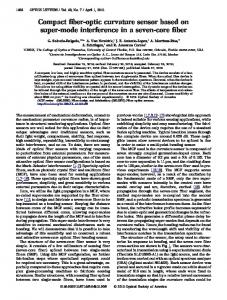
due to the air cladding on both sides of the membrane and thus prevents room temperature CW operations and higher output power. In addition to the thermal issues, since the active volume of a surface-pumped PhC laser is determined by the pumping light spot size on the device surface, which is generally larger than the cavity mode volume, lack of carrier confinement and insufficient absorbing length often result in poor pumping efficiency. In response to these issues, we have demonstrated a low-threshold, high output power InGaAsP/InP PhC laser that can achieve CW operations at room temperature by introducing a buried heterostructure (BH) active region in an InP air-bridge structure [12–14]. Due to the high thermal conductivity of the surrounding InP that is ten times or higher than that of InGaAsP, the generated heat can easily escape from the cavity. A better overlap of the active region with the cavity mode profile provides more efficient pumping, because the BH effectively confines the carrier to the active region, and also forms an ultrahigh-Q cavity with small mode volume owing to its index modulation effect on a line defect [15]. This paper presents a low power and high-speed all-optical memory based on injectionlocking bistability [16] of the buried heterostructure photonic crystal (BH-PhC) laser. The power consumption is two orders or less than previous works, and the switching time is about 60 ps. The bistability exists between the injection-locked state and the unlocked state by sweeping the optical injection power or the wavelength detuning between the master and slave PhC lasers [17,18]. A wide bistable range of input power was also demonstrated to show the potential of the proposed all-optical memory for practical uses. Based on these facts, we believe that the proposed BH-PhC laser-based optical memory is an attractive solution to realize all-optical signal processing. 2. Device The BH-PhC laser is featured with an ultra-small active region embedded in an InP PhC airbridge structure as shown in Fig. 1(a). The small active region with the size of 4 × 0.3 × 0.16 μm3 is placed within a line-defect PhC waveguide in an InP slab and consists of three InGaAs quantum wells (QWs) with a 1.55 μm photoluminescence (PL) peak, which is sandwiched between thick InGaAsP barrier layers with a 1.35 μm PL peak. The triangular lattice constant (a) and air-hole radius of the PhC are designed to be 438 nm and 100 nm, respectively. The width of the line-defect waveguide is 0.98 Wo, where Wo equals a3.
Γ
Line-defect waveguide K M
1.3µm pumping waveguide
Buried active region
InP 1.55µm waveguide (a)
Buried active region
(b)
Fig. 1. Scanning electron microscope (SEM) images of the fabricated buried heterostructure photonic crystal (BH-PhC) laser. (a) Top view. (b) Cross-sectional view as illustrated by the yellow dash line in (a). The sample was slightly etched after cleaving for better visualization of the buried active region.
Strong carrier confinement is provided by the active region, which is a general attribute of the BH. An index-modulated mode-gap cavity [15] is formed in the BH region since the refractive index of the active region is higher than the neighboring InP. Optical confinement is, therefore, obtained by the refractive index difference between the active region and the neighboring InP due to a localized band edge shift. Apart from the better matching between the generated carriers and the optical cavity mode volume provided by the buried active region, an efficient pumping is achieved also by the fact that InP is transparent to the pumping light and thus undesired absorption outside the cavity is ignorable. Figure 1(a) also shows an
#139953 - $15.00 USD
(C) 2011 OSA
Received 22 Dec 2010; revised 31 Jan 2011; accepted 31 Jan 2011; published 4 Feb 2011
14 February 2011 / Vol. 19, No. 4 / OPTICS EXPRESS 3389
offset output waveguide placed at the Γ-M direction in the vicinity of the PhC cavity, which enables optimized coupling between the cavity and the output waveguide [19]. In the fabrication aspect, the active region has to be precisely positioned within the linedefect PhC waveguide and embedded in an InP layer to prevent from being etched during the subsequent wet etching of the InGaAs sacrificial layer underneath the air-bridge structure. In addition, a flat top surface and smooth air-hole sidewalls are also critical for a high-Q cavity (~100,000 theoretically in our case). Despite the difficulty comes from the regrowth process which is required for the device fabrication, we have been able to obtain a high-quality ultrasmall buried heterostructure as shown in Fig. 1(b). More fabrication details can be found elsewhere in [12,13]. 3. Bistability characteristics The optical injection induced bistability was characterized with the experimental setup as shown in Fig. 2(a). In this setup, the BH-PhC laser was optically pumped at room temperature by a 1310 nm DFB laser through the pump waveguide. The injection light (λ inj) at a wavelength detuned (δ) from its cavity mode peak at free-running was then coupled to the 1.55 µm-waveguide with a circulator, and the power level of the injection light was digitally adjusted with an optical variable attenuator. The output spectrum was then taken by means of an optical spectrum analyzer (OSA) after the circulator. All fibers used in this setup were polarization-maintained (PM) to provide a better reproducibility of the measurement results. The coupling loss in the pump side and in the output side can be estimated to be 10 dB and 8.5 dB, respectively. Free-running -40
Att Output [dBm]
1.55 µm Tunable Laser (Injection) Injection
1.31 µm Laser Bias (Pump) BH-PhC laser
Output
OSA
Mode-A
-50 -60
inj
-70 -80 -90
(a)
Mode-B
1542 1543 Wavelength [nm]
(b)
Fig. 2. (a) The experimental setup for the optical injection. The optical injection and the output from PhC laser were connected by a circulator. “Att” stands for polarization maintained optical attenuator and “OSA” stands for optical spectrum analyzer. (b) Optical spectrum of two freerunning cavity modes with pump power of 25 µW in the PhC waveguide. The wavelength detuning between the injection light (λinj) and Mode-A is labeled as δ.
In a PhC cavity, the number of cavity modes and their resonant wavelengths as well as Q factors can be determined by designing the cavity properly. Here we designed two cavity modes with similarly high Q factors so that the two modes coexist in the operation range of interest. Although the bistable memory operation only requires one cavity mode, our device also includes the other cavity mode for a better demonstration as will be explained in the following sections. A well-controlled fabrication process can also ensure its reproducibility. Figure 2(b) shows two cavity resonant modes located at 1542.99 nm (Mode-A) and 1541.76 nm (Mode-B). The power level of the pump light was kept at 25 µW in the PhC waveguide throughout the bistability characterization, which was 1.76 times of laser threshold Pth. In this paper the power levels refer to the power in PhC waveguides, unless otherwise noted. The free-running PhC laser was lasing at Mode-B for pump power at 25 µW and 100 µW as in section 3 and section 4, respectively.
#139953 - $15.00 USD
(C) 2011 OSA
Received 22 Dec 2010; revised 31 Jan 2011; accepted 31 Jan 2011; published 4 Feb 2011
14 February 2011 / Vol. 19, No. 4 / OPTICS EXPRESS 3390
Output power @WG [dBm]
-15
Pthunlock
Pthlock
-20
-25
-30
-35
-16
-14
-12 -10 Input power @WG [dBm]
-8
-6 (a)
Inj
Inj
B
B
(b)
Inj
Inj B
(c)
B
A
(d)
A
(e)
Fig. 3. (a) The peak output power of the injection mode as a function of the injection power for a wavelength detuning of + 0.30 nm. (b-e) The output spectra of various injection levels as indicated. The injection power sweeping direction is specified by arrows ( and ). Two stable states (locked and unlocked) coexist at the same injection power of 13.5 dBm depending on the sweeping direction. The dash line on each spectrum indicates the wavelength of injection light.
Figure 3 shows an example of the injection induced bistability with a wavelength detuning of + 0.30 nm. An obvious hysteresis loop was observed as shown in Fig. 3(a). By increasing the power level of the injection light () as shown in Fig. 3(d) Fig. 3(e) Fig. 3(c), ModeA was locked to the injection light when the injection power level was greater than a certain threshold (Pthlock), and Mode-B was significantly suppressed simultaneously due to side-mode injection [16]. After injection-locking was obtained, the PhC laser was lasing at the injection wavelength instead of its cavity mode. A side-mode suppression ratio (SMSR) of more than 45 dB after locking is shown in Fig. 3 (c). A red-shift of Mode-B was also observed, which can be considered as the direct result of the refractive index change due to the carrier reduction by light injection. On the other hand, by decreasing the injection power () as shown in Fig. 3 (c) Fig. 3(b) Fig. 3(d), the locked state was maintained until a lower threshold (Pthunlock) of the injection power was reached. Depending on the sweeping direction
#139953 - $15.00 USD
(C) 2011 OSA
Received 22 Dec 2010; revised 31 Jan 2011; accepted 31 Jan 2011; published 4 Feb 2011
14 February 2011 / Vol. 19, No. 4 / OPTICS EXPRESS 3391
of the injection power, the output power had two states that are the locked and unlocked state within the hysteresis loop. In order to utilize this bistability phenomenon for dynamic memory operation, the injection light was used as the control signal while the noninjected mode (Mode-B) was used as the response signals (Fig. 4(a)). Although the bistability was also observed in Mode-A, here Mode-B was selected for a better on/off extinction ratio and easiness of optical filtering. To switch between the two states, the injection power should be located within the bistable range. The bistability was further characterized with various detuning values. As shown in Fig. 4(b), clear hysteresis loops were observed for an injection detuning (δ) greater than + 0.17 nm, and the wider bistable range can be achieved with larger δ. The minimum injection power, which was used as a switching bias, can be as low as 7 µW in the PhC waveguide for δ = + 0.17 nm as shown in the inset of Fig. 4(b). By extracting the two thresholds (Pthlock and Pthunlock), Fig. 5 shows a broader view of the bistable range in relation to injection power levels and wavelength detunings. A very wide relative hysteresis width ( = 2 × (Pthlock - Pthunlock)/(Pthlock + Pthunlock)) is shown to be 133% for δ = + 0.70 nm. Although a larger bistable range can be achieved by trading off a higher injection power, a sufficiently large hysteresis loop can already be obtained with tens of µW injection power (for example, a bistable region ranging from 90 µW to 160 µW for δ = + 0.45 nm) as shown in Fig. 4. The large bistable ranges at the low injection power levels make this optical memory insensitive to the drifts of wavelength and injection power due to thermal fluctuation, therefore suitable for practical uses.
Mode-B unlocked
locked
B Inj (data) (control)
(a)
locked
0
5 10 15 20 25 Injection power @ WG [ W]
Output power (linear)
A Inj (control)
Output power (linear)
B (data)
unlocked
0
= = = = = = = = = =
+0.45nm +0.41nm +0.37nm +0.33nm +0.29nm +0.25nm +0.23nm +0.21nm +0.19nm +0.17nm
50 100 150 Injection power @ WG [ W]
(b)
Fig. 4. (a) Schematic of bistable operation. (b) Static bistability characteristics of Mode-B with various wavelength detuning values. Curves are offset in vertical axis for visual clarity. The sweeping directions of injection power are indicated by arrows.
#139953 - $15.00 USD
(C) 2011 OSA
Received 22 Dec 2010; revised 31 Jan 2011; accepted 31 Jan 2011; published 4 Feb 2011
14 February 2011 / Vol. 19, No. 4 / OPTICS EXPRESS 3392
0.8 Pthunlock
Bistable range Pthlock
0.6 0.4
0.5 0.4
Detune ( ) [nm]
Detune ( ) [nm]
0.7
0.3 0.2 0.1
0.3 0.2 0.1 0 0
0 0
Lock threshold Unlock threshold
0.05
0.1
Injection power @ WG [mW]
0.2 0.4 0.6 0.8 1 Injection power @ WG [mW]
1.2
Fig. 5. Bistable range indicated by the lock-unlock thresholds.
4. Memory operation To demonstrate the dynamic switching functions, we used pulse modulated injection light (set and reset) as the input signal to switch between two bistable states. In this demonstration, we chose 100 μW pump power in the PhC waveguide, which was 7.04 times of laser threshold Pth, in order to achieve faster switching time. The input pulse width of both set and reset signals was 200 ns with 2 μs period as shown in Fig. 6(a). The switching bias power level, i.e. injection power, and the wavelength were set within the bistable range. The output signal was first amplified with an erbium-doped fiber amplifier (EDFA) followed by an optical filter, and then fed into an oscilloscope. Here Mode-B was selected using an optical filter for the demonstration of the memory operation. Figure 6(b) and 6(c) show the dynamic memory operations, in which the Mode-B signal acts as the inverted output in response to the set and reset input signals. Mode-B first stayed at its original ON state if no signal applied. When a set pulse was given, Mode-B switched to OFF state and stayed at OFF state until a reset pulse was given. The dynamic operations as shown in Fig. 6(b) and 6(c) were at switching biases of 71 μW (11.5 dBm) and 22 μW (16.5 dBm) with the same wavelength detuning at + 0.24 nm. The memory holding time was determined by the interval between the set and reset input signals that was 1 μs in this case, and this number can be much longer without any theoretical limitations. The rise time and fall time of the output signals at 11.5 dBm switching bias were measured to be 58 ps and 65 ps as shown in Fig. 6(d) and 6(e), and they became 36 ps and 138 ps at 16.5 dBm as shown in Fig. 6(f) and 6(g). Note that the rising edge was triggered by the reset signal and the falling edge was triggered by the set signal in Fig. 6. The rise time was considered to be limited by the inverse of the relaxation oscillation frequency which was determined by the pump power and wavelength detuning [20] and can be improved by biasing the PhC laser well above its threshold. The rise times at the same pump power were therefore similar in Fig. 6(d) and 6(f). On the other hand, we can observe that the fall time at 11.5 dBm switching bias power was about half of that at 16.5 dBm, since the fall time was considered dependent on the signal power and can be improved by increasing the signal power level. The extinction ratio between ON and OFF states was 6.75 dB in Fig. 6(b). The non-zero OFF level is believed to be limited by the amplified spontaneous emission (ASE) from the EDFA used at the output before the oscilloscope.
#139953 - $15.00 USD
(C) 2011 OSA
Received 22 Dec 2010; revised 31 Jan 2011; accepted 31 Jan 2011; published 4 Feb 2011
14 February 2011 / Vol. 19, No. 4 / OPTICS EXPRESS 3393
200ns
200ns
2 μs
Reset
rise
= 58 ps
Output [a.u.]
(a)
Time [100 ps/div]
Output [a.u.]
1 μs
fall
= 65 ps
Output [a.u.]
Set 2 μs
(d)
Time [100 ps/div]
(e)
(b)
= 36 ps
fall
= 138 ps
Output [a.u.]
rise
Output [a.u.]
(c) Time [ s/div]
Time [100 ps/div]
(f)
Time [100 ps/div]
(g)
Fig. 6. All-Optical bistable memory operation: (a) schematics of the input switching signal; (b) output waveforms of Mode-B signal with switching power at 11.5 dBm and (c) at 16.5 dBm in the PhC waveguide; (d) the rising edge and (e) the falling edge of the output waveform at 11.5 dBm; (f) the rising edge and (g) the falling edge of the output waveform at 16.5 dBm.
We have also demonstrated the wavelength tolerance of the dynamic memory operation by varying the injection wavelength at the same injection power. As shown in Fig. 7, correct memory operation exists within a wavelength detuning range of 0.07 nm at an injection power of 11.5 dBm. While a larger operable range can be easily achieved with higher injection power, this demonstration provides a direct evidence of the sufficient wavelength tolerance at injection power of only tens of μW. Note that the lowest possible switching bias and switching pulse energy were not fully explored in this demonstration. Since the lowest tested switching bias power for a clear bistable operation was only 7 μW at pump power of 25 μW as shown in Fig. 4 inset, it is reasonable to expect a dynamic memory operation with an even lower switching bias. Further investigations will focus on obtaining the lowest achievable pumping power and switching energy. In this paper, the power consumption of the device is defined as the power consumed in the PhC waveguide, and we suppose, without loss of generality, this is what it really requires for driving the device, especially considering the case in PhC-based photonic integrated circuits. Comparing to other electrically-pumped optical memories, the estimated total system power of our device, which includes the power for generating the optical pump, is still advantageous. For example, by incorporating properly designed spot-size converters (loss < 1dB possible) [21,22] and concurrent edge-emitting lasers with high power conversion efficiency (> 70%) [23], the fiber coupling loss and required external power can be kept minimal, and the total power consumption can still be within 200 µW. In our future path of development, we will use electrical pumping methods for our BH-PhC laser by means of approaches such as lateral current injection (LCI) via ion-implantation [24] or selective growths of n- and p-type lateral claddings on a semi-insulating InP substrate [25]. In this electrically-pumped BH-PhC laser, the device can be reset by simply turning off the bias current.
#139953 - $15.00 USD
(C) 2011 OSA
Received 22 Dec 2010; revised 31 Jan 2011; accepted 31 Jan 2011; published 4 Feb 2011
14 February 2011 / Vol. 19, No. 4 / OPTICS EXPRESS 3394
Output [a.u.]
δ small
Time [1 s/div]
= = = = = = = = = =
+0.20nm +0.21nm +0.22nm +0.23nm +0.24nm +0.25nm +0.26nm +0.27nm +0.28nm +0.29nm
δ mid
δ large
Fig. 7. All-Optical memory operation at various injection detuning values for switching power at 11.5 dBm in the PhC waveguide.
5. Conclusion We have demonstrated the optical injection locking bistability in the ultra-compact BH-PhC laser with only 25 μW power consumption. A successful demonstration of dynamic memory function is obtained at 100 μW pump power and tens of micro-watt (μW) switching power with rise time and fall time of 58 ps and 65 ps. With a wide hysteresis width at low power consumption, we believe that this optical memory is sufficiently robust for practical use. To the authors’ best knowledge, this is the first demonstration of an all-optical memory based on PhC lasers. The superiority of BH-PhC laser in compact size, capability of high integration, and low power consumption has made it a strong candidate for next-generation OPS routing systems. Acknowledgement Part of this work was supported by the National Institute of Information and Communications Technology (NICT), Japan.
#139953 - $15.00 USD
(C) 2011 OSA
Received 22 Dec 2010; revised 31 Jan 2011; accepted 31 Jan 2011; published 4 Feb 2011
14 February 2011 / Vol. 19, No. 4 / OPTICS EXPRESS 3395