FESCA 2009
An Agile MDA Approach for Service-Oriented Components Simona Motogna1,2 Department of Computer Science Babe¸s Bolyai University Cluj-Napoca, Romania
I. Laz˘ar, B. Pˆarv, I. Czibula1,3 Department of Computer Science Babe¸s Bolyai University Cluj-Napoca, Romania
Abstract Two important principles that drive the agile MDA processes are immediate execution and test first development. This paper presents a component model, called iComponent, that allows the development of executable models based on agile principles and service orientation. In order to ensure simple and fast definition of component operations, we use a concrete syntax for UML structured activities and a corresponding UML profile. The study also includes a mapping of iComponent to some existing service-oriented component frameworks (iPOJO, OSGi, SCA). The proposed platform-independent component model is part of a framework for component definition, validation and composition. Keywords: agile MDA, service-oriented components, component model, executable UML, component-based development
1
Introduction
Component-based approaches lead to applications developed and deployed as a set of components. The main benefits of these approaches consist of loose coupling among the application components, third-party component selection, and increased possibilities for reuse. Traditional component-based approaches typically lead to applications which are statically configured as a set of components. This means that benefits outlined above typically extend only to the development part of the software system life-cycle, not to the run-time part [10]. 1 This work was supported by the grant ID 546, sponsored by NURC - Romanian National University Research Council (CNCSIS) 2 Email:
[email protected] 3 Email: ilazar,bparv,
[email protected]
This paper is electronically published in Electronic Notes in Theoretical Computer Science URL: www.elsevier.nl/locate/entcs
Motogna
Nowadays there are component models and frameworks which allow components unavailable at the time of application construction to be integrated later into application’s life-cycle, i.e. after its installation. Most frameworks that support dynamic availability of components use the general principles of service-oriented component models [9]. These models merge the principles of service-oriented computing [24] into a component model. A service-oriented component approach to build an application typically includes the following steps: (1) Decompose the application into a collection of interacting services. The semantics of each service is described independently of each other, and of any implementations. This way, the service specification will provide a basis for substitutability. (2) Define a set of components implementing the application services. A component may provide and require zero or more services. (3) Define composite components that guide the application execution. These composite components are described in terms of service specifications, and the concrete implementations of services will be resolved at run-time. One of the main ideas for simplifying the construction of components is to separate the business logic of a component from the non-functional requirements related to the container in which the component execution will be managed. In such a context, developers concentrate first on implementing the business logic of the component, then they configure declaratively the deployment of components. Another important aspect of component models and frameworks refers to the development approach. Approaches in which modeling is at the core of the development activities also simplify the component construction process [1]. Well-known such approaches are based on UML and MDA. UML 2 [21] established itself as the standard for modeling software systems. However, most commonly, UML models are used as blueprints that are fill in with code, and the current agile development processes (e.g. agile model-driven development, test-driven development) tend to minimize the modeling phase and the usage of UML models. MDA framework [19] provides an approach for specifying systems independently of a particular platform and for transforming the system specification into one for a particular platform. MDA is considered the OMG approach to Model Driven Engineering (MDE). MDE approaches cand be based either on MDA, or on Domain Specific Modelling. MDE appeared as a solution to applications that have to deal with increased platform complexity and domain concepts. MDE aims to raise the level of abstraction in program specification and increase automation in program development [1,2]. The system can be developed based on models at different levels of abstractions, and then model transformations partially automate some steps of program development. But development processes based on MDA are not widely used today because they are viewed as heavy-weight processes - they cannot deliver (incrementally) partial implementations to be executed as soon as possible. In this context, executing UML models became a necessity for development processes based on extensive modeling. For such processes models must act just like code [14], and UML 2 and its Action Semantics [21] provide a foundation to construct executable models. In order to make a model executable, it must contain a complete and precise behavior description. But, creating such a model is a tedious 2
Motogna
task or an impossible one because of many UML semantic variation points. Executable UML [14] means an execution semantics for a subset of actions sufficient for computational completeness. Two basic elements are required for such subsets: an action language and an operational semantics. The action language specifies the elements that can be used while the operational semantics establishes how the elements can be placed in a model, and how the model can be interpreted. An agile MDA process [13,19] applies the main Agile Alliance principles (e.g. testing first, immediate execution) into a classical MDA process. In other words, in order to make such processes models to act just like code, they must be executable. These approaches represent the driven principle of our framework for Software Component Definition, Validation, and Composition, ComDeValCo [25]. It constituens are: (1) a modeling language, used to describe components models; (2) a component repository, which stores and retrieves software components and systems, and (3) a toolset, aimed to help developers to define, check, and validate software components and systems, and to provide maintenance operations for the component repository. This paper proposes an agile MDA development approach for the development of service-oriented components. The component execution is based on the infrastructure built for executable UML structured activities [11] by adding component manipulation capabilities to the existing ComDeValCo Action Language (AL) [25]. Component definition uses a platform-independent component model for dynamic execution environments called iComponent [12], which follows the main idea of iPOJO [10], but at a platform-independent level in the context of agile MDA processes. The iComponent model is adapted such that it will allow assembling and deploying components and services altogether, using the following basic extensions: •
new stereotype, provides and requires, with corresponding attributes for service properties, are defined for publishing and requiring services;
•
it’s introducing new stereotypes, Domain and Node in order to configure the system deployment.
The rest of the paper is organized as follows. The next section presents the UML profiles for executable UML components, using structured activities to define components’ operations, and the iComponent model. The third section explains the use of the agile MDA approach based on an example, while the last one contains a comparison between iComponent and other service-oriented component models, and draws some conclusions and future development plans.
2
UML Profiles for Executable UML Components
2.1
Executable UML Structured Activities
As part of the ComDeValCo framework, we have defined an Action Language (AL) [11,25], that is a concrete syntax for UML structured activities, and graphical notations for some UML structured activity actions. The AL will be used in the proposed approach for defining the bodies of the operations. That’s why it was designed based on simplicity and easiness of use. 3
Motogna
The Action Language (AL) was introduced in order to simplify the construction of UML structured activities, in a more concise form: •
it defines a concrete syntax for representing UML structured activity nodes for loops, sequences of actions and conditionals;
•
the syntax is also used for writing assignment statements and expressions in structured activity nodes;
•
it includes assertion based constructs: pre, post, assert, loopVariant, loopInvariant, that allow program execution inspection, using OCL expressions.
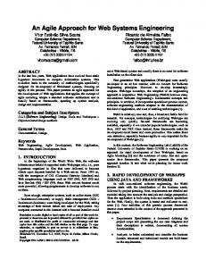
In order to illustrate the conciseness of AL, we consider a short example, depicted in Figure 1. Figures 1-(a) and 1-(b) show the graphical and textual notations for the assignment q := s + 1. Both notations can be compiled to the same UML repository model presented in Figure 1-(c). Figure 1-(d) shows the push model for evaluating the expression s+1 and storing the result to an activity variable q.
Fig. 1. Assignment: q := s + 1 in AL and corresponding UML activity
The definitions of AL constructs for other UML activities, such as sequence, conditional, and loop, are similar and can be found in [11]. The compatibility between AL and UML, or other tools, is provided by generating a representation which is conformant with the UML metamodel and fUML action subset [22]. 2.2
i Component - Injected Components
iCOMPONENT (injected component) ([12]) has been designed as a platformindependent component model that can be used to develop service-oriented components for dynamic execution environments. The set of stereotypes used to model injected components are: Module, Component, Domain, Node, DynamicExecutionEnvironment, provides, requires, validate, invalidate, controller, and config, as shown in Figure 2. Modules. The Module stereotype extends the UML 2 DeployedArtifact metaclass and represents the unit of deployment. A Module may contain classes, interfaces, components, component instances, and other resources. The set of model 4
Motogna
Fig. 2. iComponent stereotypes
elements that are manifested in the module (used in the construction of the module) is indicated by the manifestation property of the DeployedArtifact. Component types. The Component stereotype extends the Class metaclass (from UML StructuredClasses) and represents a component type. A Component may define properties and methods as being a structured class. The configuration properties of a component must be marked with the config stereotype, which contains an attribute for indicating a setter operation to be called when the component container injects the value for a given configuration property. The provides stereotype can be used for publishing services and their properties. This stereotype extends both UML InterfaceRealization and Port metaclasses in order to allow modeling of published services as simple classes that implement interfaces, as well as components that have attached ports. The property attribute can be used to export the service properties, expressed as a set of (key,value) pairs. The requires stereotype can be used for requiring services. This stereotype extends both UML Association and Port metaclasses in order to allow modeling the required services as simple classes that have unidirectional associations with interfaces, as well as components that have attached ports. The filter attribute can be used to filter the required services, based on their properties. The UML provided/required interfaces do not contain such attributes, which explains why the provides and requires stereotypes were introduced. The two attributes are essential in the component model corresponding to service-oriented components because they provide the necessary form for expressing the properties associated to a service. For example, let’s consider two components EnglishDictionary and FrenchDictionary implementing the same interface Dictionary and an EnglishSpellChecker component that requires a Dictionary. If the two dictionary concrete components are adnotated with a property representating the language (language=English, respectively language=French), then the spell checker component can choose which interface implementation to use: filter=(language=English). Composite components. UML 2.0 offers two ways of modeling subcomponents: subcomponents as parts and subcomponents as nested elements. The composites in iComponent use UML composite structures in order to indicate their internal structure. In this context, subcomponents modeled as parts are shared 5
Motogna
components which may be referenced by many composite components. Component Instances. The execution environment creates (target) component instances in two ways: (a) by creating the instances specified by Modules, and (b) by creating the instances specified as parts of composite Components. In the case (a), the module containing the component definition indicates that a corresponding component instance must be created. In the case (b), if a composite structure diagram attached to the component contains an instance specification with an interface type, then an instance of a component that implements the interface will be created when such a component type is available. After creation, the instance is bound to the composite instance. Moreover, if such a bound instance dissapears, another compatible one can be instantiated to replace the missing service required by the composite. This mechanism is called dynamic substitution of services. In both cases, the component instances are specified as InstanceSpecification objects of type Component. The values of the InstanceSpecification’s slots are used to configure the component instance’s properties (using member field injection). The component’s required references (services) will be injected by the execution environment as described below. Component binding. The execution environment creates for each component instance a container, wrapping the instance, that automatically manages the activities of providing or requiring interfaces. When a component is added to the dynamic execution environment, it enters the invalid state. The component enters the valid state and its provided interfaces are published into a service registry when the container resolves its dependencies, i.e. the required interfaces. Lifecycle controllers. iComponent proposes a simple notification mechanism between a component and its container, as shown in Figure 3: (a) After a module is installed it enters the Installed state. When all the model elements required by a module (its module dependencies) are available, the module enters the Resolved state. A resolved module can be started and the module enters the Active state. (b) The modules configured component instances will be created in the Active state and destroyed when the module leaves this state. When a module becomes active, implicitely the components enter the invalid state, and become valid only afer validation. A valid component can require its container to enter the invalid state. This is achieved by configuring a component boolean property as controller property using the controller stereotype.
Fig. 3. (a) Module statemachine; (b) Component statemachine
6
Motogna
Service registries. The execution environment offers a global service registry in which component instances publish their provided interfaces. Other component instances may acquire references to these global services automatically through their wrapper containers. But, in order to isolate the component instances and services of an application, the instances of a composite are not published globally by default. Each composite component has its own service registry which is used by all component instances living in the same composite for providing and requiring services. Because a composite may contain other composites, a mechanism for importing and exporting services is needed. This way, a composite can export a service to its parent or can import a service from its parent. Nodes and dynamic execution environments. Node stereotype extends UML Node metaclass. A node may deploy several modules, and therefore possible several components instantiated by these modules. The DynamicExecutionEnvironment stereotype extends Node, in which we may use: (a) the properties associated to a service that is published by a component, and (b) dynamic binding using filters for selecting the services required by a component, in a similar way to the iPOJO approach [10]. Domain. A Domain represents a complete configuration for system deployment, and consists of nodes and connectors between nodes. It may have several nodes, each containing several components. Here a node is seen as a process on a computer. The binding of the components in a specific domain is regardless of the nodes in which the components are deployed.
3
The Proposed Agile MDA Approach
Any UML case tool can be used to construct the models presented in this section. In order to execute the models the tool should also conform to fUML specification for executable models [22]. Our ComDeValCo workbench is such a tool, being designed according to these requirments [12]. The proposed agile MDA approach consists of applying the following steps in the specified order: (1) the model is described on different layers: services, structure and deployment, then (2) for simple components proceed with test-first component development. Each of the following subsection describes in more details a step of our proposal and exemplifies it on a simple case study. Let’s consider a case study that prints the product prices of a given store. The store has a product catalog representing information about products (code, description, and price without taxes and discounts). The printing procedure must take into account the discount strategies the store may have for each product and the application of VAT. 3.1
Services model
The services model, typically defined by the system analyst, describes the services that will be provided by the system. The modules that refer to services model may include any data type, such as classes, interfaces, or components. The interfaces contain the operations provided by the services. 7
Motogna
Figure 4 presents the model corresponding to our case study, and illustrates the separation of responsibilities. The StoreService interface contains the required operations for printing the product prices with taxes and discounts. StoreService’s operations can simply delegate execution to their corresponding operations from ProductCatalog and PriceCalculator. The PricingStrategy interface is designed to represent both discount and VAT price adjustments. The services module includes all these interfaces as well as the Product business entity.
Fig. 4. Services model
3.2
Structural model - composite components
The structural model, typically defined by the system architect, indicates component instances that will implement the services. At this stage, the system is decomposed into a set of components, simple or composite. Composite components help the architect to decompose the system functionality in an hierarchical way. Each composite component has attached a composite structure diagram, describing its internal structure, using component parts (simple or composite) and connectors between ports, and specifying which components will be instantiated. The rules for the construction of the diagram are: •
the internal structure of a component uses instances of other components, connected through ports;
•
the provided and required ports, as well as their multiplicity, should be specified;
•
to select a certain service implementation satisfying some criteria, use the property attribute corresponding to provides and filter attribute coresponding to requires;
•
the InstanceSpecification objects indicate which components should be created and their corresponding property values.
Figure 5 shows the composite structure diagram of the Store composite component. Store uses three shared subcomponents, of which one, PriceCalculatorComposite, is a composite too. The provided and required interfaces are represented as ports and the components are linked using connectors. Instances will be created according to the rules given in Section 2. When Store detects that a type that implements the ProductCatalog interface is installed, an instance of a component that implements the ProductCatalog interface will be created and the ProductCatalog service will be published into the Store’s registry. The 8
Motogna
Fig. 5. Store composite component - internal structure
vatCalculator service will be imported from the global registry. An instance of the concrete component StoreServiceImpl and an instance of PriceCalculatorComposite will be created.
Fig. 6. Price calculator composite component - internal structure
Figure 6 explains how hierarchical composition works: components acquire services from their parent, and provide services to their parent. The priceCalculator composite component takes vatCalculator service from its parent, and provides PriceCalculator to its parent. 3.3
Deployment model
The deployment model is specified using UML Node and DynamicExecutionEnvironment constructs. The dependencies from Figure 7 represent the required runtime dependencies between modules. All monolithic implementations reference only interfaces, but composite components may use other components as parts (see Figure 5). 9
Motogna
Fig. 7. Module dependencies
At this moment the domain has to be specified, with its included nodes, and the deployment of modules within nodes. Next question refers to which components will be instantiated during execution and to the nodes involved in each instantiation process.
Fig. 8. Domain and nodes
Figure 8 illustrates the domain for our case study and specifies which services will be available in the dynamic execution environment. There are two nodes, corresponding to CatalogApp and TaxServices. Coresponding to the domain specification above, Figure 9 shows the component instances created at runtime their corresponding nodes. StoreComposite acquires vatCalculatorImpl service and publishes it for its part components, then creates instances for its parts. In a recursive way, PriceCalculatorComposite (see Figure 6 for its internal structure) acquires vatCalculatorImpl service from its parent and publishes it. 3.4
Test-first component development
When the decompostion is complete, the next step is to define simple or monolithic components solving the initial problem. For each new feature of the system being developed, our proposed agile MDA process includes the sequence of following testfirst design steps [3]: 10
Motogna
Fig. 9. Component instances
Add a test. Developers write the tests using either graphical or textual notations. Both are compiled into the same UML repository model. During the activity construction process, the framework allows the use of inline expressions, represented and evaluated according to the pull model for actions.
Fig. 10. Product discount tests
Figure 10 shows how tests for ProductDiscount module are created, including initialization of the component properties productCode and discountPercentage. Using AL, the implementation: assert 90 = pricingStrategy.adjustPrice(’’3’’,100); is introduced in testProductWithDiscount method, and assert 100 = pricingStrategy.adjustPrice(’’1’’,100); is introduced in testProductWithoutDiscount method in ProductDiscountTest. Run the tests. Developers write pre- and post-conditions expressed as OCL expressions. The syntax of AL includes pre- and post- constructs, which are taken into account when the system is run. The methods of the components from ProductDiscount module (see Figure 10) have an empty body, they are only specified using pre- and post-conditions. Add production code. The third step is to update the functional code to make it pass the new test. Again, both graphical and textual syntax of AL can be used, favoring the application of design by contract principles. By running the tests shown from Figure 10, the code is updated as presented in Figure 11, namely the adjustPrice method is implemented in the following way: if (productCode = self.productCode) return (1-discountPercentage/100)* price; else return price; Run the tests. This last step means running the tests again. Once the tests 11
Motogna
pass the next step is to start over implementing a new system feature.
Fig. 11. Product discount
Figure 12 presents CatalogPrinter definition, which use the validate stereotypes in order to register callback operations invoked when the component enters the Valid state.
Fig. 12. Catalog printer
4
Related Work
As shown in the first section, two important issues for simplifying the construction of components are (1) the separation of the business logic of a component from its non-functional requirements and (2) the application of a model-driven development (MDD) approach. Both are hot research topics and several academic and commercial solutions targeting component models and service orientation are under development. Traditional commercial component models such as Component Object Model (COM) [15], Enterprise Java-Beans 2.1 [26], and CORBA Component Model [18] use specific application programming interfaces, and does not offer a clear separation between functional and non-functional requirements. This restricted interface usage decreases the potential reuse degree of the components. Among the MDA approaches which address the traditional component models (e.g. Corba Component Model) we mention the standard specification for deployment and configuration of component-based distributed applications [20]. Other MDA approaches which refer to embedded systems [6,8] or pervasive systems [4,5,16] address the dynamic execution environment features and the separation problem. Academic solutions, such as Fractal [6] and SOFA 2.0 [7] are open component models that provide all dynamic features but do not offer a clear separation of the functional and non-functional requirements. iPOJO (injected Plain Old Java Objects) [10] is a service-oriented component framework supporting the service-oriented component model concepts and dynamic availability of components, following the POJO approach (Plain Old Java Objects). 12
Motogna
iComponent
iPOJO
SCA
Domain
-
Domain
Node
-
Node
DynamicExecutionEnvironment
OSGi implementation
-
Module
Bundle
Contribution
Component
Component
Component
Composite component
Composite
Composite
provides
provides
Service
requires
requires
Reference
validate and invalidate
validate and invalidate
-
controller
controller
-
config
Property
Property
Table 1 iComponent, iPOJO, and SCA mappings
All service-oriented aspects, such as service publication, the required service discovery and selection are managed by an associated component container. The operations in iPOJO are similar to iComponent operations, but our approach is platform-independent, while iPOJO is restricted to Java. Also, the current version of iPOJO does not provide a clear separation of the business logic and non-functional requirements for all operations discussed above. More precisely, only dynamic availability of components and composition of components are supported, while the dynamic reconfiguration of components is performed using the OSGi Configuration Admin service only. Another framework which supports dynamic availability and reconfiguration of components is the OSGi framework [23], which offers a service-oriented component model. OSGi components are bound using a service-oriented interaction pattern, and their structure is described declaratively. Again, OSGi does not offer a clear separation between business logic and the non-functional requirements. Service Component Architecture (SCA) Assembly Model specification [17] proposes a definition of composite components similar to iPOJO; in addition, the components may be distributed in several locations/nodes within the same domain. Another remarkable feature of SCA is that it allows specification of component implementations which are not necessary classes; they can be bussiness processes also. However, there are also some drawbacks of SCA: it doesn’t indicate any solution for controlling the lifecycle of components and does not allow the user to attach properties to a published service and to filter services specifying some conditions. Table 1, enumerates the main objects needed to develop service-oriented components for dynamic execution environments and gives the mapping between these objects from the proposed model, iComponent, and iPOJO and SCA frameworks. 13
Motogna
As the table suggests, the main difference between iComponent and SCA on one hand, and iPOJO, on the other hand, is that iPOJO does not support distributed service architecture. iComponent supports it, by distributing the modules in the nodes of the dynamic execution environment, as illustrated in Figure 8. Comparing iComponent with SCA, one may observe that SCA does not have lifecycle controllers, i.e. a notification mechanisms between a component and its container such that the component can participate to its lifecycle events.
5
Conclusions and Future Work
We have presented iComponent, a platform-independent component model for dynamic execution environments, and extended it for service-oriented component models. We have also introduced an agile MDA approach for constructing executable models. The iComponent profile was extended by adding component composition features which allow us to assemble components and services together and by adding new stereotypes, Node and Domain, for specifying component deployment locations. We have also shown that it is possible to map our developed models to specific platforms, like iPOJO and SCA. As a future direction, we intend to build the concrete mappings for these platforms. The UML profile was defined in such a way that it can be constructed with any UML tool and can be executed in any executable UML tool or with ComDeValCo workbench, which is in progress of extension. In earlier phases of the project, it was defined for UML structured activities and extended with the definition of platform-independent components based on the proposed UML profile for injected components. The approach can be used by a large community of component developers, since it conforms to the standards of UML and MDA and the defined extension provides a complete model driven for service-oriented components. Another future plan is to include bussiness processes in our approach, in an intension to minimize the differences with SCA approach. The toolset component of our framework will also be enhanced with model transformation capabilities.
References [1] Balasubramanian, K., A. Gokhale, G. Karsai, J. Sztipanovits, and S. Neema, Developing Applications Using Model-Driven Design Environments, Computer, 39(2006), 33–40. [2] Batory D. Multilevel models in model-driven engi-neering, product lines, and metaprogramming, Model-Driven Software Development (IBM System Journal), 45(2006), URL: http://www.research.ibm.com/journal/sj/453/batory.html. [3] Beck, Kent, Test-Driven Development By Example, Addison Wesley, 2002. [4] Bottaro,A., J. Bourcier, C. Escoffier, and P. Lalanda, Autonomic Context-Aware Service Composition. In: IEEE International Conference on Pervasive Services, 223-231(2007). [5] Bourcier,J., A. Chazalet, M. Desertot, C. Escoffier, and C. Marin, A Dynamic-SOA Home Control Gateway. In: IEEE International Conference on Services Computing, 463 - 470(2006).
14
Motogna [6] Bruneton, E. et al. An Open Component Model and Its Support in Java. In: Component-Based Software Engineering, LNCS 3054(2004), 7-22, Springer, Berlin / Heidelberg. [7] Bures,T. et al., SOFA 2.0: Balancing Advanced Features in a Hierarchical Component Model. In: Proceedings SERA (2006), 40-48. [8] Cano,J., N. Martinez, R. Seepold, and F. L. Aguilar, Model–driven development of embedded system on heterogeneous platforms. In: Forum on Specification and Design Languages (2007). [9] Cervantes,H. and R. S. Hall, A Framework for Constructing Adaptive Component-Based Applications: Concepts and Experiences, Component-Based Software Engineering, LNCS 3054(2004), 130-137, Springer, Berlin / Heidelberg. [10] Escoffier, C. and R. S. Hall, Dynamically Adaptable Applications with iPOJO Service Components. In 6th Conference on Software Composition (SC07), 113-128(2007). [11] Lazar,Ioan, S. Motogna, B. Parv, I-G. Czibula and C-L. Lazar, An agile MDA approach for executable UML structured activities. Studia Univ. Babes-Bolyai, 2(2008), 101–114. [12] Lazar,Ioan, B. Parv, S. Motogna, I-G. Czibula and C-L. Lazar, iComponent: A Platform-independent Component Model for Dynamic Execution Environments, In: 10th Int. Symp. SYNASC(2008), accepted. [13] Mellor,Stephen J., Agile MDA, Technical report, Project Technology, Inc., 2005. [14] Mellor, Stephen J. and Marc J. Balcer, Executable UML: A Foundation for Model-Driven Architecture, Addison Wesley, 2002. [15] Microsoft Co., Component Object Model (1995) URL: http://www.microsoft.com/com/. [16] Munoz, J., V. Pelechano, and J. Fons, Model Driven Development of Pervasive Systems, ERCIM, 58(2004), 50-51. [17] OASIS, SCA Service Component Architecture. Assembly Model Specification, Version 1.1(2007), URL: http://www.oasis-opencsa.org/sca. [18] Object Management Group, CORBA Components Specification, Version 3.0.( 2002), URL: http://www.omg.org/technology/documents/formal/components.htm. [19] Object Management Group. MDA http://www.omg.org/docs/omg/03-06-01.pdf.
Guide
Version
1.0.1.
(2003),
URL:
[20] Object Management Group, Deployment and Configuration of Component-based Distributed Applications Specification, Version 4.0. (2006), URL: http://www.omg.org/technology/documents/formal/deployment.htm. [21] Object Management Group, UML 2.1.1 Superstructure http://www.omg.org/cgi-bin/doc?ptc/07-02-03/.
Specification.,
(2007),
URL:
[22] Object Management Group,Semantics of a Foundational Subset for Executable UML Models (FUML), (2008), URL: http://www.omg.org/spec/FUML/. [23] OSGi Alliance, OSGi Service Platform Core Specification, Release 4, Version 4.1.(2007), URL: http://www.osgi.org/. [24] Papazoglou,M. and D. Georgakopoulos, Service-Oriented Computing, Communications of the ACM, 46(2003),25-28. [25] Parv,B., I. Lazar, and S. Motogna, ComDeValCo Framework–the Modeling Language for Procedural Paradigm, Int. J. of Computers, Communications Control, 3(2008),183-195. [26] Sun Microsystems, Enterprise JavaBeans http://java.sun.com/products/ejb/docs.html.
15
Specification
(2003),
URL: