An Algorithm for Project Tasks Selection Using Intent Tree Structure. C.O. Anyaeche*, O.E. Charles-Owaba, and M.A. Oladipo Department of Industrial and Production Engineering, University of Ibadan, Ibadan, Nigeria. E-mail:
[email protected]*
[email protected]
ABSTRACT Networking is a very valuable instrument for planning and control of projects and many believe that the failure or success of project execution depends largely on sound project activities network or schedule. Although several attempts have been made to develop project activities scheduling, yet, it remains not fully resolved. This work is based on the intent tree structure approach. It employs work breakdown structure using a contextual relationship, and an algorithm was developed. The algorithm was applied to effectively identify the set of activities required to accomplish each sub goal and for identifying the precedence constraints of a set of project activities. These were used to draw the network for building an office. This procedure for developing an orderly sequencing operation, as in this work, can also be applied in planning involving large activities especially new projects where data may not be adequate. (Keywords: project, activities, precedence, algorithm)
task precedence constraints and their interrelationships. Knowledge of such project components are useful for developing a project activities network or schedule. Over the years, project network has been a very valuable instrument for planning and control of important projects. Many believe that the failure or success of project execution depends largely on being able to develop sound project activities network or schedule. Perhaps, it is for this reason that several attempts to develop project activities scheduling techniques have been reported (Oladipo, 2003; Anyaeche, 2009). Since the problem of networking had been in existence for long, different approaches have been used to address the problem (Hillier and Lieberman, 2006; Taha, 2007). The two network analysis commonly known are Critical Path method (CPM), and Program Evaluation and Review Technique (PERT). Different names attributed to CPM/PERT show that the tools are very important in project planning. The planning and control of large- scale industrial projects may be accomplished by using the activity network as the modeling technique.
INTRODUCTION A project is a plan or scheme of activities intended to achieve a predetermined set of goals. The activities may be those in building construction, journey to outer space, new town development, the setting of a new tertiary institution a service or even a manufacturing concern, to mention just a few. The associated goals naturally follow: building construction, space exploration, town development, etc. For orderly operation, timely completion, effective cost and quality control of operations, there is the need for a procedure for systematic identification of all relevant project activities, The Pacific Journal of Science and Technology http://www.akamaiuniversity.us/PJST.htm
The CPM uses a deterministic approach, which suits a project whose time duration can be accurately predicted i.e. a project which is repetitive in nature e.g. building construction work. PERT takes into account the difficulty of estimating the duration of individual activities. In research and development project in particular, the estimator would be unwilling to provide a single value for the duration, but rather to have a most optimistic, a most pessimistic and a most likely duration for an activity and standard deviation of the distribution can be found. PERT uses a beta frequency distribution (this is a skewed distribution), which provides a satisfactory model of reality.
–311– Volume 10. Number 2. November 2009 (Fall)
The use of PERT/CPM technique for planning purposes provides a natural framework for reporting and control purposes. It is an excellent system for keeping track of all activities in a large project where there are thousands of interdependent tasks (Hillier and Lieberman, 2006).
applies to other many varied situations. Therefore, planning is extensive and critical. There are several planning tools available in the literature (Lester, 2003 Babcock and Morse, 2005; Hillier and Lieberman, 2006; Taha, 2007). They include: (i) Statement of work.
The basis of all these techniques is to portray pictorially all the steps and tasks that must be accomplished to complete a project in the form of a network of events and activities (Aritua, 2009: Anyaeche, 2009). There are other names used for the network technique that have been developed (Babcock and Morse, 2005; Hillier and Lieberman, 2006). However, analytical procedures are not computationally efficient for a general network problem. Attempts have been made to develop approximation techniques. Also for resource leveling, heuristics rather than algorithms are widely used (Taha, 2007). If the resource level, activities, sub-goals and the outcomes are known, or relatively predictable, then the intent structure could be applied to determine the precedence relationship, and this would give a good pictorial perception of the network. This work is an attempt to stimulate efforts in addressing this gap in knowledge.
OBJECTIVES The following are the specific objectives of this study: i.
Develop a procedure for identifying the set of activities required to accomplish a sub goal.
ii.
Develop a procedure for identifying the precedence constraints of the activities using the intent structure technique.
iii.
Draw the network of a project using the task identification and precedence procedure developed.
(ii) The milestone schedule. (iii)The work breakdown structure (iv) Gantt (bar) chart (v) Network scheduling system such as PERT or CPM other project network models (vi) Resource allocation methods. Some of these, that are of interest here, are briefly described below. Network Systems: There are terminologies used in network systems, some are described below. A graph consists of a set of function points called modes, with certain pairs of the modes being joined by lines called branches (or arcs, links or edges). In a graph the circles designating stations are the nodes, and the roads connecting them are the branches. A network is considered to be a graph with a flow of some type in its branches. Thus sources may be considered as the generators of the flow and sinks as the absorbers of that flow. Work Breakdown Structure: This involves breaking a project into its components. very process of establishing the work breakdown structure provides an orderly procedure to ensure that all of the needed specialist skills are identified. The most important step is to formulate the problem so that the study objectives are clearly defined as problems to be solved. Given these objectives, the major tasks in such an analysis are: To collect information on:
PROJECT PLANNING TOOLS A project was regarded as a set of activities that has never been done exactly that same way before, however, the current thinking is that it The Pacific Journal of Science and Technology http://www.akamaiuniversity.us/PJST.htm
(i) Tasks to be performed and alternative methods of performing them (ii) Technological relations between the tasks
–312– Volume 10. Number 2. November 2009 (Fall)
(iii) Activity times and costs. In order to be sure that these tasks fit together at the end, the lead analysts must, throughout the study give thought to the integration or synthesis of all these tasks. This is necessary in order to ensure that both the implicit assumptions made in the process of developing the network, as well as the explicit ones, are in consonance with each other and with the underlying measure of effectiveness The act of generating the network itself is a very valuable planning aid, since it demands precise definition and agreement as to what has to be done, and what events depend upon specified ends, (Crawford and Pollack, 2004). Fuller discussions on the tools could be obtained from the literature including Babcock and Morse (2005); Hillier and Lieberman (2006); Taha (2007). Identification of activities and precedence constraints for activities with the precedence relationship are important and it is generally realized that the fundamental characteristics of all the activities involved must be performed in some well defined order (Thomas and Mully, 2007; Aritua et al., 2009). It appears that for an unknown precedence relationship, identification of activities will be achieved if the following assumptions hold: i. A project is finite- it has a definite beginning and a specific ending point. ii. A project consists of a number of segments that can be broken down into separate –components; activities and tasks. In other word, a project can be partitioned into identifiable parts. iii. A project is a one- time effort. It is non repetitive. The salient feature here is that repeating the activities either part or whole implies extraneous consumption of resources outside the budget, thus not exactly the same activity. iv. Because many tasks are involved that require an assortment of knowledge and skill, projects tend to be complex. v. Projects are predictable. In this respect, a system development for a project would result if a predetermined course of tasks performance is The Pacific Journal of Science and Technology http://www.akamaiuniversity.us/PJST.htm
followed and different if otherwise.
METHOD OF STUDY Networking with precedence diagrams are becoming more attractive, because no dummies are necessary and it is easier to understand by people familiar with flow sheet. The Intent Structure: The network approach in this work, uses the intent tree structure because it facilitates visual perception of the structure of the entire problem (Sage, 1987; Uher, 2003). The particular intent structure chosen will depend on the complexity of the problem to be solved. For simple problems it may be chosen by inspection, however, for the more complex problems it is necessary to resort to different methods of forming the intent structure. Here we use the tree structure diagram to systematically map out the full range of activities that must be accomplished in order to reach a desired goal. It is also used to identify all the factors contributing to a problem under consideration. Major factors identified by an interrelationship diagraph can be used as input for a tree structure. One of the strengths of this method is that it forces the user to examine the logical and chronological links between tasks. This assists in preventing a natural tendency to jump directly from goal or problem statement to solution. The tree structure is indispensable when a thorough understanding of what needs to be accomplished is required, together with how it is to be achieved, and the relationship with these goals and methodologies. The starting point for developing a list of activities is a work breakdown structure using a contextual relationship. The most challenging part is the determination of the precursor activity (ies) for each activity. In most project activities networking, it is assumed that the time to perform each of the activities and their relative ordering are known. In CPM and PERT models, as in this work, the arcs in a network represent operationally and logically indivisible part of a project. The precedence constraints required to carry out these activities produce a directed acyclic network structure.
–313– Volume 10. Number 2. November 2009 (Fall)
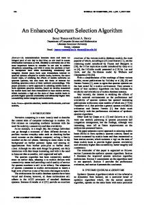
Identification Of Task: A task can be considered as a set of activities performed by one or more resources on a project. Its inputs are from one or more resources outside of itself. Its output is required for one or more resources outside of itself. A task cannot begin or complete work until all the required preceding inputs are received. A task is not complete until all the required output is not only finished (according to the task completion criteria) but also passed on to all the subsequent resources requiring this task's output. Task definition must include identifying all the required inputs, what format they must be in, and which task(s) must provide the input before this task can begin work. Task completion criteria must include what the required outputs are, what format they must be in, and what task requires those outputs in order to begin its tasks. When To Split A Task: There are two main reasons to 'break' a task into its components: i. If the input is required from another resource(s) or technological relation after a task has started and before it is completed, break the task accordingly. The earlier task has the originally identified required inputs. Its output in addition to the outside resource task is required as the input for the new task. ii. If an output is required from this task, in order for another task to begin, and if the output that occurs prior to this task meeting its task completion criteria, break the task accordingly. If an earlier task is the work up to the point of output; it will have two outgoing arrows; one to the tasks that requires its outputs and the other to the portion remaining of the original task. Activity Precedence Relationship: Project networking is possible for all processes that can be split into more operations whereby their interrelationship will be shown clearly and in a logical manner (Thomas and Mully, 2007). But in a situation whereby the immediate preceding activity is not known and the project is new to the analyst, determination or identification of activity (ies) may not be easy; the effective application of such project analysis requires the close cooperation and co-ordination between analysts primarily responsible for the study and each of the other individuals providing inputs. Starting with the outcome (output deliverables) to the necessary inputs, would give a good guide. An The Pacific Journal of Science and Technology http://www.akamaiuniversity.us/PJST.htm
example is given in Figure 1.
i
j
Figure 1: Diagraph of outcome (j) to input (i) relationship.
System Objectives: An overall system objective is a broadly defined goal; while the achievement indicates system success. To achieve this goal, the many elements of the system - men, equipment, and facilities, etc. must be designed or directed toward this end. The structure for this objective has several significant qualities that bear heavily upon the system planning and evaluation process; in this regard it is typical of overall system objectives and merits examination. The economy and efficiency implied by this objective are of the broadest nature; they refer to the total cost in manpower, equipment, money, time and whatever resources are consumed in the operation. The objective of the last phase in a sequence can be expected to most closely match that of the overall sequence. If the overall system is to meet this objective, the actions of each system must meet certain objectives in turn and this again, is typical of the general objective structuring problem. The Structuring Of Objectives: Each activity has a sub-objective that, if accomplished, ideally will result in the integrated sequence of achieving its overall objective or goal. Our concern is with establishing sub-objectives and our approach is to start with the over-all system objective and to 'work-back' as it were, to determine the implication of the over-all objective upon the subobjectives in each phase. This same approach is then employed with each phase for each sub-objective of the complementary activities. The logical developments of the objectives and sub objectives have their analytical and planning implications; and these bear significantly on the project. System Subordination Matrix: This is a matrix which includes all the elements pertaining to the system and shows the subordination relation among all the elements (interrelationship using precedence relationship).
–314– Volume 10. Number 2. November 2009 (Fall)
It is a special form of transitivity of the following form and holds if eij = 1, and then eji = 0. This means that if there is a relevant interaction between i and j, then there is none between j and i.
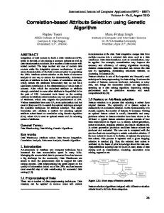
A matrix display of Figure 2 using the above contextual relationship is presented in Table 1. The following rule then holds: (a) Diagonal entry rule: all entries on the main diagonal of the matrix, eii will be zero i.e. an activity does not relate to itself.
Contextual Relationship Question: This is the question which indicates the attainment of objective i necessary or desirable to the attainment of objective j using the notation, eij thus:
(b) Double entry on 1 rule: If an element i is subordinate to j, eij =1; and eji = 0; which indicate that feedback or circularity is not allowed. It often indicates an inadequate analysis of the objective statement and that j cannot be subordinate to i.
= 1, if yes eij = 0, if otherwise
(c) Transitive element: If an element i is subordinate to j and j in turn is subordinate to one or more kn, then i is also subordinate to the same Kn ; i.e if eij = 1, ejk = 1; then eik = 1.
Before the matrix is formed, contextual statement is used to describe the position in which there is relationship with 1; and 0 for where there is no relationship (Sage, 1986; Kerzner, 2003).
We now examine the efficacy of the procedure with the application to a real life case example by applying it to construction of an office building.
Digraph (Length of Path): This is characteristic of either being related or not being related which a binary matrix will represent. We present an example involving activities for an example, P1, P2, P3, P4 and P5 as shown in fig. 2. Here, P1, is an input to P2; while P2, P3, P4 are inputs to P5
P1
P2
MODEL APPLICATION Case Example: Building Construction Of An Office Project. A set of activity follows as in table 2. We use this as a case example.
SOLUTION
P5
P3
Following the steps highlighted earlier, the identification of the task and building of the network is carried out thus:
P4 Figure 2: A Sketch of Diagraph of Inputs.
Table 1: A matrix Display of Contextual Relationship.
1 2 3 4 5
1 0 0 0 0 0
2 1 0 0 0 0
The Pacific Journal of Science and Technology http://www.akamaiuniversity.us/PJST.htm
3 0 1 0 0 1
4 0 0 1 0 0
5 0 0 0 0 0
–315– Volume 10. Number 2. November 2009 (Fall)
Table 2: Data for Building an Office. S/No 1 2
Activity A B
3
C
4 5 6 7
D E F G
8
H
9
I
10
J
11 12
K L
13
M
Activity Description Prepare site Reinforcement in foundation Planking
S/No 14 15
Activity N O
16
P
Concrete works Column starters Form work to columns Block work in Foundation Coating of columns in Foundation Return feel
17 18 19 20
Q R S T
Activity Description Fixing of column Bars Form work to beams and First floor slab Fixing of replacement Bars to Beam and Slab Form work to staircase Casting of staircase Fixing of electrical fittings Plumbing works
21
U
Fixing of trusses and sheets
22
V
Remove excavated material Placing of hard cores Fixing of Columns Level and compact Ground floor slab
23
W
Fixing of Frame doors and windows Rendering of vertical wall
24 25
X Y
General clearing, Painting Handover
26
Z
End
Step 1: Identify the objective (goal) The objective of the project is the completion of an office building. Step 2: List the deliverables (sub-goals) The deliverables are the sub-goal or the activity description necessary to make the objective realizable. These are listed in table 2. Work break down structure is normally used for this.
From the list, to have a complete office building construction, input i needed for this phase in order to start task j are fixing of window frames and door (V), rendering of vertical walls (W) and general cleaning painting (X) and handover (Y). This is as shown in Figure 4.
Office building V
Step 3: Beginning at the end of the project, put the objective at the far right hand side, use contextual question to answer what inputs are needed in order to start the task and place the answer to the left of the objective, drawing an arrow from (tail) the deliverables (sub-goal) to (tip) the objective. This is displayed in Figure 3.
Hand over Y
End Figure 3: Diagraph of end and handover of the project.
W
x
Y
End
Construction
Figure 4: Diagraph for adding activities X, V, and W.
The next set of activities are as shown in Figure 5. Here the input(s) are fixing of electrical fittings (T), plumbing works (U) and fixing of trusses and sheets (V).
For the next phase, we consider the input(s) i are needed in order to start this task-j ?
The Pacific Journal of Science and Technology http://www.akamaiuniversity.us/PJST.htm
–316– Volume 10. Number 2. November 2009 (Fall)
S
V
Y
W
U
End
x
T
Figure 5: Diagraph for adding activities S, T, and U.
In order to start task S, U, and T, input Q and R (i.e., forming work to staircase and casting of staircase) are as shown in Figure 6.
Q
R
S
V
Y
W
U
The inputs are ground floor and fixing of columns bar (L, M). These activities are added as shown in Figure 8. The construction of the network, the procedure are followed strictly using the method by asking the contextual (statement) question of what inputs are needed in order to start the next task? The inputs are block work in foundation, coating of coating of column in foundation and placing of hard cores (G, H, K). These are shown in Figure 9.
End
x
T
To achieve the objective goal of starting the input Q and R (i.e., forming work to staircase and casting of staircase) the inputs are N,O and P (i.e., casting of columns) from work to beams and first slab and fixing of replacement bars to beams and slab. These are depicted in Figure 7.
Figure 6: Diagraph for adding Q and R.
Q
N O P
S
V
R
Y
W
U
End
x
T
Figure 7: Diagraph for adding N, O, and P.
Q
N
L
O
V
Y
W
U
R
P
M
S
End
x
T
Figure 8: Diagraph for adding L and M.
G
L
H K
Q
N O
M
P
R
S U T
V
Y
W
End
x
Figure 9: Diagraph for adding G, H, and K.
The Pacific Journal of Science and Technology http://www.akamaiuniversity.us/PJST.htm
–317– Volume 10. Number 2. November 2009 (Fall)
I E
G H
O P
M
K
J
S
Q
N
L
V
R
Y
W
U
End
x
T
Figure 10: Diagraph for adding E, I, and J.
L
I C B
G
E
Q
N
S
U R
P
M
K
J
F
Y
W
O H
D
V End
x T
Figure 11: Diagraph for adding C, B, and D.
L
I C
A
B
Start
E
Q
N
G
S
F
J
K
U M
P
Y
W
O H
D
V
R
End
x T
Figure 12: Diagraph for adding A.
In Figure 10, the inputs that are needed are the tasks (E, I, and J ): remove excavated material, column starter, and return feel. In order to start the next task, the required inputs as shown in Figure 11, are activities C, B, D and F i.e. Planking, reinforcement in foundation, concrete work and form work to column are added.
The Pacific Journal of Science and Technology http://www.akamaiuniversity.us/PJST.htm
Finally for the last phase, the input that is needed here is task (A) i.e. site set up. This is as shown in Figure 12. This concludes the diagram for building the office, as required. Check the logic of the network after completing the exercise and identify any missing or previously hidden dependencies (arrows), by following a reverse order from A to Y, Z.
–318– Volume 10. Number 2. November 2009 (Fall)
ACTIVITIES AND PRECEDENCE IDENTIFICATION ALGORITHM The following steps will help in identifying the task to be performed when developing a precedence relationship.
office building project. This methodology could apply to other endeavors, however, the starting point is to break the down using break down structure techniques.
RECOMMENDATIONS FOR FURTHER WORK 1. Identify the objective (title, goal) of the project. What is the project to accomplish? 2. List the deliverables (Sub-goals). Usually the deliverables are defined in quantitative terms, sometimes in qualitative or mixture of both. 3. Beginning at the end of the project put the goal at the far right-hand side. This is the target you're aiming for. 4. Establish a contextual relationship by determining what input(s) are needed in order to start this task"? The answer to the question assists in helps to identifying what the preceding task(s) should be and helps to avoid getting more detailed than necessary at this point.
In this work we considered activities individually. It is recommended that further work would aim to address set of tasks (or activities) taken together or simultaneously. A computerized version of that and the present work can be developed and applied to different situations other than construction. The key focus would be on structure or pattern recognition, synthesis and analysis.
REFERENCES 1.
Anyaeche, C.O. 2009. “Preparation of Site Progress Report”. A Research Manuscript, in the Department of Industrial and Production Engineering, University of Ibadan, Nigeria.
2.
Aritua, B., Smith, N.J., and Bower, D. 2009, “Construction Client Multi-Projects: A Complex Adaptive Systems Perspective”. International Journal of Project Management. 27(1) 72-79.
3.
Babcock, D.L. and Morse L.C. 2005. Managing Engineering and Technology. Prentice-Hall: Delhi, India.
4.
Crawford, L. and Pollack, J. 2004. “Hard and Soft Projects: A Framework for Analysis”. International Journal of Project Management. 22(8):645-653.
5.
Lester, E. I. 2003. Project Planning and Control. McGraw-Hill: Amsterdam, The Netherlands.
6.
Kerzner, H. 2003. Project Management: A Systems Approach to Planning, Scheduling, and Controlling. John Wiley & Sons, Inc.: Hoboken, NJ.
7.
Hillier and Lieberman. 2006. Introduction To Operations Research. McGraw-Hill: New York, NY.
8.
Oladipo, M.A. “Project Activities and Precedence Constraints, Identification and Networking”. An M.Sc. Project Report, Department of Industrial and Production Engineering, University of Ibadan, Nigeria.
9.
Sage, A. 1977. Methodology for Large Scale Systems. McGraw-Hill: New York, NY.
5. Place each of your answers to the left of project objective. Draw an arrow from (tail) the deliverable to (tip) the objective. Pick one/any task to the left of the objective. Establish, what inputs are needed in order to start/perform this task. Write it down, put it to the left, draw the arrow and check (as shown in step 4). Follow this procedure down until you reach the beginning of the project/or time now. 6
Check the logic of your networks. After completing step 5, you are ready to check the logic and identify any missing or previously hidden dependencies (arrows). To check, start at the beginning of the project, and follow the reverse order .i.e. from A to Z.
CONCLUSIONS This work examined the procedure for identifying precedence relationship among activities. It developed an algorithm for identifying precedence relationship and successfully applied it in an The Pacific Journal of Science and Technology http://www.akamaiuniversity.us/PJST.htm
–319– Volume 10. Number 2. November 2009 (Fall)
10. Taha, H.A. 2007. Operation Research: An Introduction, Prentice Hall: New York, NY. 11. Thomas, J. and Mullaly, M. 2007. “Understanding the Value of Project Management: First Steps on an International Investigation in Search of Value”. Project Management Journal 38 (3):74 – 89. 12. Uher, T.E. 2003. Programming and Scheduling Techniques A UNSW Press Book. University of New South Wales Press, Ltd.: Sydney, Australia.
SUGGESTED CITATION Anyaeche, C.O., O.E. Charles-Owaba, and M.A. Oladipo. 2009. “An Algorithm for Project Tasks Selection Using Intent Tree Structure”. Pacific Journal of Science and Technology. 10(2):311320. Pacific Journal of Science and Technology
The Pacific Journal of Science and Technology http://www.akamaiuniversity.us/PJST.htm
–320– Volume 10. Number 2. November 2009 (Fall)