Scientific Research and Essays Vol. 7(2), pp. 177-189, 16 January, 2012 Available online at http://www.academicjournals.org/SRE DOI: 10.5897/SRE11.1182 ISSN 1992-2248 © 2012 Academic Journals
Full Length Research Paper
An efficient quantum-dot cellular automata full-adder Sara Hashemi, Mohammad Tehrani and Keivan Navi* Nanotechnology and Quantum Computing Laboratory, Shahid Beheshti University, G.C, Tehran, Iran. Accepted 31 October, 2011
The most important mathematical operation is addition. Other operations such as subtraction, multiplication and division are usually implemented by adders. An efficient adder can be of great assistance in designing arithmetic circuits. QCA is a promising technology which seems to be a good candidate for the next generation of digital systems. So, an efficient QCA full-adder will facilitate creating QCA computational and arithmetic systems. In this paper, two high performances QCA fulladders are presented. They have a very dense structure and constructed using new kinds of five-input majority gates. One of the proposed designs has a robust structure. In this design the presented design rules for constructing a robust QCA circuit have been considered. In contrast to the previous designs constructed using a five-input majority gate, in the proposed QCA full-adders the outputs come out from the same side of the circuit. Also, the input and output signals are not surrounded by the other cells and can easily be accessed. The proposed robust QCA full-adder dominates all the previous robust designs in terms of area, delay and complexity. Using this design, ripple carry adders with different word sizes (that is, 4, 8 and 16) are constructed. In this paper, QCA designer, a common QCA layout design and verification tool is employed to verify and simulate the proposed five-input majority gates and QCA full-adders. Key words: Quantum-dot cellular automata, full-adder, five-input majority gate, robustness, ripple carry adder. INTRODUCTION The technology of semiconductor fabrication has been changed rapidly in the last decades but some applications require less power and more speed. There is a paradox in CMOS technology: the speed is not gained unless more power is consumed and if the power is reduced to save energy it results in speed reduction. Therefore, the designers prefer to use new technologies based on nanoelectronics instead of CMOS such as carbon nanotube field effect transistors (CNFET) and quantum-dot cellular automata (QCA). With these new technologies more integration and speed as well as less power consumption are achieved. Carbon nanotube field effect transistor (CNFET) (Dresselhaus et al., 2001) is same as CMOS in many aspects and could be replaced in most applications. CNFET has more compaction and consumes less power, but a quantum-dot cellular
*Corresponding author. E-mail:
[email protected]. Tel: +982129904195. Fax: +98-21-22431804.
automata is completely different from conventional CMOS technology. It consumes less power due to its specification which is hidden in a QCA cell structure. QCA cells as well as, the circuits utilizing them have been fully fabricated and tested by researchers (Kummamuru et al., 2003; Orlov et al., 2003; Timler and Lent, 2003). Several studies have been performed towards implementation of molecular QCA structures which can operate at room temperature (Hu et al., 2005; Lent et al., 2003; Srivastava and Bhanja, 2007). Some of the other researchers such as (Bonyadi et al., 2007; Cho and Swartzlander, 2007, 2009; Cho, 2006; Hänninen and Takala, 2010; Hashemi et al., 2008; Kim et al., 2005, 2007; Navi et al., 2010a, b; Rahimi et al., 2007; Sayedsalehi et al., 2010; Tougaw and Lent, 1994; Vankamamidi et al., 2005; Vassilios and Ioannis, 2010; Vetteth et al., 2002; Wang et al., 2003; Zhang et al., 2004, 2005) have focused on designing efficient QCA circuits. In (Hashemi et al., 2008; Vassilios and Ioannis, 2010) efficient designs for QCA multiplexers have been presented. (Hashemi et al., 2008) introduces an efficient
178
Sci. Res. Essays
and robust 2:1 QCA multiplexer layout. This layout is implemented using the multilayer QCA wire crossing scheme. In (Vassilios and Ioannis, 2010) a 2:1 QCA multiplexer constructed using the coplanar wire crossing scheme is introduced which can be a useful component in designing 2n to 1 QCA multiplexers. Designing efficient QCA memory cells is one of the attractive fields in QCA. Line based and loop based structures generally are used to design a QCA memory cell. In (Vankamamidi et al., 2005) a novel QCA line based parallel memory has been introduced. Some of the other previous researches (Kim et al., 2005, 2007) have been focused on designing robust QCA circuits. In (Kim et al., 2005, 2007) some design rules for constructing a robust majority gate and coplanar wire crossing scheme against sneak noise paths have been introduced. Reduction of the number of QCA majority gates and optimization of QCA circuits is another attractive field in QCA. In some of the previous studies (Bonyadi et al., 2007; Zhang et al., 2004) required methods for QCA circuit optimization are investigated. Adders are one of the basic components in designing arithmetic circuits like residue number systems and alike (Mollahosseini et al., 2010; Timarchi and Navi, 2009), therefore designing a robust, dense and simple full-adder is of great importance (Navi et al., 2009a, b). To date, several studies have been done on QCA adder designs (Cho and Swartzlander, 2007, 2009; Cho, 2006; Hänninen and Takala, 2010; Kim et al., 2007; Navi et al., 2010a, b; Rahimi et al., 2007; Sayedsalehi et al., 2010; Tougaw and Lent, 1994; Vetteth et al., 2002; Wang et al., 2003; Zhang et al., 2005). The first QCA full-adder design was presented in (Tougaw and Lent, 1994). This design is constructed using five three-input majority gates and three inverters. Another QCA full-adder using the same logical structure was introduced in (Vetteth et al., 2002). This design in contrast to the first design incorporates QCA clocking scheme. A simpler QCA full-adder was presented in (Wang et al., 2003). This full-adder is composed of three three-input majority gates and two inverters. Using this design, different layouts for a QCA full-adder have been presented to date (Cho and Swartzlander, 2007, 2009; Cho, 2006; Hänninen and Takala, 2010; Kim et al., 2007; Zhang et al., 2005). These layouts are different in terms of area, delay and number of QCA cells (complexity). In (Hänninen and Takala, 2010; Kim et al., 2007) robust QCA full-adders have been introduced. These designs have a more robust structure against sneak noise paths. Recently, a novel QCA full-adder design was introduced (Rahimi et al., 2007). This design is composed of one three-input majority gate, one inverter and a new kind of majority gates: a five-input voter. This study also presents an unconventional form of QCA cells. Based on the presented design in (Rahimi et al., 2007) different QCA full-adders have been introduced (Sayedsalehi et al., 2010, Navi et al., 2010 a, b). These designs are different in terms of area, number of QCA cells (complexity) and
delay. As mentioned earlier, some of the previous studies have been performed towards implementation of QCA cells, while some have been done on designing efficient QCA circuits. In this study, two new efficient QCA fulladders are presented. The manufacturing concepts are out of scope of this paper. In order to design efficient QCA full-adders, two new five-input majority gates constructed using ordinary QCA cells are introduced. It is worth mentioning that, one of the proposed five-input majority gates and QCA full-adder constructed using this component have a robust structure. In these structures, the presented design rules for constructing a robust QCA circuit have been considered (Kim et al., 2005, 2007). Simulation results reveal that the proposed QCA fulladders have a very dense structure. In these designs, the input and output signals are not surrounded by the other cells. The outputs come out from the same side of the circuit and can easily be accessed. Regarding the reliable structure of the robust QCA full-adder, it is used to design ripple carry adders with different word sizes (that is, 4, 8 and 16). Simulation results show that these designs lead to significant improvements in terms of area; delay and complexity in comparison to the constructed ripple carry adders with the previous best design (Hänninen and Takala, 2010). QUANTUM-DOT CELLULAR AUTOMATA Quantum-dot is a potential hole which can arrest electrons, because electrons are unable to overcome their barrier and jump out side of the dot. The diameter of each dot is small enough to make its charging energy greater than kBT, where kB indicates the Boltzmanns’ constant and T is the operating temperature (Niemier, 2004). A QCA cell can be realized with semiconductor, metal, magnets and molecules. At first the metal-island implementation was used to demonstrate the concept of QCA (Amlani et al., 2000; Orlov et al., 1998; Toth and Lent, 1999). In this method, quantum dots are implemented using aluminum islands. In the semi conductor (or solid state) QCA implementation, (Single et al., 2000) QCA devices can potentially be implemented with the same highly advanced semiconductor fabrication processes which are used to implement CMOS devices (Smith et al., 2003). In this implementation, quantum dots are created from standard semi conductive materials such as InAs/GaAs (Suraprapapich et al., 2007) and GaAs/AlGaAs (Gardelis et al., 2003; Perez-Martinez et al., 2007). In molecular QCA (Lent et al., 2003; Li et al., 2001; Lieberman et al., 2002; Lu et al., 2007), the basic cell is a pair of identical molecules (Lent et al., 2003). The molecular devices can operate at room temperature and have a very high density. In magnetic QCA, a nao magnet is the basic cell (Haque et al., 2004). Cowburn and Wellands nanodot QCA Automata (Cowburn and
Hashemi et al.
Quantum Dot
179
Input a
Electron
A
Device cell
Output OUT
Input c
C
A B C
Maj 3
M(A,B,C)
B Input b
P=-1
(a)
P=+1
Figure 1. Illustration of a QCA cell's logic states.
1
0
(b)
1
1
Figure 2. Signal propagation in a QCA Wire.
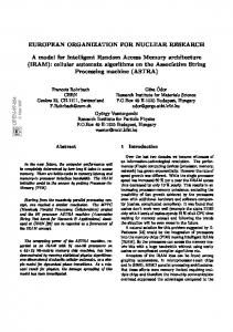
Welland, 2000), Parish and Forshaws Bi-stable Magnetic QCA (Parish and Forshaw, 2003, 2004) and field couple nanomagnets (Csaba et al., 2002, 2004) are the popular schemes of the magnetic QCA. The advantages and disadvantages of the presented materials (semiconductor, metal, magnets and molecules) have been investigated in (Srivastava, 2007). In this study, a four-dot cell model is considered and a set of four quantum-dots in a square shaped arrangement is called a QCA cell, where there are only two excess electrons. In a QCA cell, the most important force which affects the electrons is coulumbic repulsion. So, the electrons always pose diagonally in the square to increase their distance and take the farthest position from each other to minimize the total system's energy. It is obvious that the electrons never stay on the same side of the square since they cannot maximize their distance. A QCA cell has two diagonal states: when the electrons are on the cell's main diagonal, they represent the logic "1" and the other diagonal shows the logic "0" (Figure 1). A QCA wire could be made by arranging some QCA cells in a line. When two cells are close together, their electrons force each other and try to get minimum energy. The system energy would be minimized only when the cells' states are the same. In other words, when the first cell has a specific value, it copies its value to the neighbor cell and so on. Hence the signal could propagate through the line of cells and they work like a wire as shown in Figure 2. Basic logic elements in QCA are inverters and threeinput majority gates. A three-input majority gate has three inputs, one voter cell and one output. The voter state is determined according to the input cells' states. If most of them have status "1", the voter takes "1" and if the most inputs have "0", voter sends "0" to the output (Figure 3a).
Figure 3. (a) A QCA majority gate (b) Illustration of a QCA inverter.
When an input of a majority gate is always "1", an "OR" gate is made (Equation 1). An "AND" gate is also made when an input is stuck at "0" as shown in Equation 2. The inverter has a very simple structure. As shown in Figure 3 (b) it can be implemented using 11 QCA cells:
𝑀𝑎𝑗 𝐴, 𝐵, 1 = 𝐴 + 𝐵
(1)
𝑀𝑎𝑗 𝐴, 𝐵, 0 = 𝐴. 𝐵
(2)
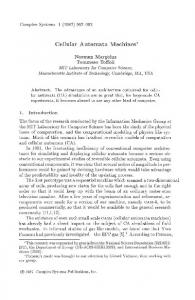
A QCA clocking zone is a group of QCA cells which are controlled by a same QCA clock. In QCA, four clocking zones are considered. The schematic of a QCA wire constructed using four clocking zones are shown in Figure 4a. It is worth mentioning that there is a 90° phase delay from one clocking zone to the next one as shown in Figure 4b. In (Kim et al., 2005, 2007), suitable QCA clock assignments to make a functional QCA three-input majority gate and coplanar wire crossing scheme are introduced. Using these clocking rules, a more reliable QCA circuit against sneak noise paths is achieved. The schematics of a robust majority gate and coplanar wire crossing scheme is shown in Figure 5a and b. As shown in Figure 5a, three different clocking zones are required to make a functional majority gate. Based on this figure, it is clear that in a robust majority gate, the input signals are positioned at the first clocking zone. In order to synchronize the affect of the input signals on the device cell, the middle QCA cells are positioned at the second clocking zone. Finally, the result is transmitted using QCA cells which are positioned at the third clocking zone. Based on Figure 5b, it is clear that two QCA clocking zones with 90° phase delay are required to implement a robust coplanar wire crossing scheme. MATERIALS AND METHODS Here, previous QCA five-input majority gates as well as two new
180
Sci. Res. Essays
Zone0
Zone1
Zone2
Zone3
(a) Switch
Hold
Release
Relax
clock0
(a)
Relax
Switch
Hold
Release
Release
Relax
Switch
Hold
(b)
Figure 6. (a) a 3D QCA cell (b) a five-input majority gate presented in (Rahimi et al., 2007).
clock1
clock2
Hold
Release
Relax
FIVE-INPUT MAJORITY GATES
Switch
clock3
Time
(b) Figure 4. (a) A QCA wire with four clocking zones (b) QCA clocks wave forms.
(a)
(b)
Figure 5. (a) A robust QCA majority gate (b) a robust coplanar crossing scheme constructed using the presented design rules in (Kim et al., 2005; Kim et al., 2007).
designs are introduced. Previous QCA full-adder designs are presented subsequently. Using the new five-input majority gates, two new QCA full-adders are introduced. The robust QCA full-adder will be used to construct ripple carry adders with different word sizes.
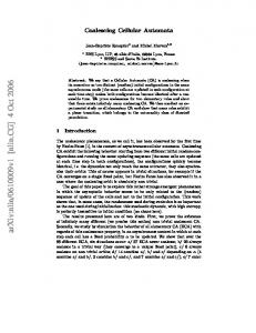
A three-input majority gate was introduced previously. Only one implementation has been presented for a three-input majority gate to date, but a five-input majority gate can be implemented using several designs. The first design for a five-input majority gate was introduced in Rahimi et al. (2007). This design is based on a three dimensional (3D) QCA cell. A 3D QCA cell is like a cube which has eight quantum dots on its corners where four surplus electrons are trapped (Figure 6a). The schematic of the presented five-input majority gate (Rahimi et al., 2007) is shown in Figure 6b. However, owing to some problems in simulation and physical implementation of 3D QCA cells in comparison to the classic ones, this design seemed not to be appropriate, at least at present. Another QCA five-input majority gate was introduced in (Navi et al., 2010a). In contrast to the previous structure (presented in Figure 6), this design is implemented using ordinary QCA cells. In this design, the inputs do not have the same effect on the output. One of the inputs affects the output from one path but the other inputs affect the output in two ways. Also, in this design the output is surrounded by the input QCA cells and it cannot easily be accessed. Regarding the position of the output signal, this design is not so practical to implement larger QCA circuits. Navi et al. (2010b) presents another QCA five-input majority gate. This design as same as the previous structure (Navi et al., 2010a) is constructed using ordinary QCA cells. In this design, in contrast to the previous design (Navi et al., 2010a), the output is not surrounded by the other cells and therefore, it can easily be accessed. In other words, this structure does not need any wire crossover to transmit the output signal. Therefore the output signal can easily be used as the input of the other QCA circuits. Using this five-input majority gate a QCA full-adder is presented in (Navi et al., 2010b). Subsequently, two QCA five-input majority gates are introduced. In one of these designs, the presented QCA clocking rules for constructing a robust majority gate (Figure 5a) have been considered and it has a robust structure. These designs are shown in Figure 7a and b. In the proposed designs, the inputs are shown by A, B, C and D. Based on Figure 7, it is clear that the value of the input D has been used as the two inputs of the proposed five-input majority gates. Therefore, these designs are suitable for implementing QCA full-adders which are constructed using three and five-input majority gates and inverters. In these full-adders the inversion of the carry value is used as the two inputs of the fiveinput majority gate (Rahimi et al., 2007). The first design is shown in Figure 7a. As shown in this figure, the output signal is not
Hashemi et al.
(a)
(b) Figure 7.
Figure 7. Illustration of the proposed five-input majority gates (a) the first design (b) The second design with considering the design rules presented in (Kim et al., 2005, 2007).
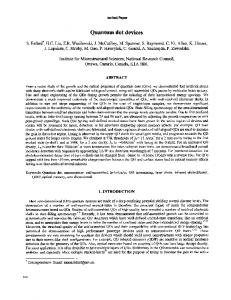
surrounded by other cells. Therefore, this structure doesn’t need any QCA wire crossover to transmit the output signal and this value can easily be used as the input of the other QCA circuits .In this structure, the seven middle QCA cells are device cells which produce the output. As shown in Figure 7a, the input QCA cells are positioned at the first clocking zone, while the middle QCA cells and the output wire is positioned at the second clocking zone. It is clear that there is a 90° phase delay between these clocking zones. The second design is shown in Figure 7b. In this design, the presented design rules for constructing a robust majority gate (Kim et al., 2005, 2007) have been considered. As shown in this figure, the inputs are positioned at the first clocking zone. The eight middle QCA cells (device cells) which make the five-input majority gate value are positioned at the second clocking zone and the output is transmitted using QCA cells which are positioned at the third clocking zone. Based on this figure, it is clear that there is a 90° phase delay between one clocking zones to the next one. Also, in this design two diagonally positioned QCA cells are used in the output. The first one transmits the inversion value of the five-input majority gate. This QCA cell is positioned diagonally to maximize the distance between the input and output QCA cells. Simulation results demonstrate that this reduces the noise effect and produces the inversion of the five-input majority gate. As shown in Figure 7b, the final value is produced using the second diagonally positioned QCA cell. In this study, the proposed five-input majority gates were simulated using QCA Designer (Walus et al., 2004) version 2.0.3. In these simulations, both bi-stable and coherence vector engines (QCA designer documentation) were used to simulate the proposed designs. It is worth mentioning that these simulations were done using the default parameters of both simulation engines (QCA designer documentation) and using both engines, same results were achieved which shows the accuracy of the proposed designs. The simulation result of the proposed designs is shown in Figure 8. As shown in this figure, the output is valid after the first falling edge of the clock2.
PREVIOUS QCA FULL-ADDER DESIGNS Various QCA full-adders have been presented to date. The first one (presented in 1994) is composed of five three-input majority gates and three inverters (Tougaw and Lent, 1994). The schematic of this design is shown in Figure 9. This full-adder uses QCA coplanar wire
181
crossing scheme. It is implemented in one layer using 192 QCA cells. In this design QCA clocking concepts are not considered. In Vetteth et al. (2002) another QCA full-adder using the same logical structure and coplanar wire crossing scheme is presented. In contrast to the previous design, this full-adder incorporates QCA clocking scheme and takes 14 clock phases (3.5 clock cycles) to generate outputs. This full-adder was used in designing a 4-bit CLA (Vetteth et al., 2002). A simpler QCA full-adder is presented in (Wang et al., 2003). This full-adder is composed of three three-input majority gates and two inverters (Wang et al., 2003). It uses QCA coplanar wire crossing scheme and takes 5 clock phases (1.25 clock cycles) to produce outputs. Hence, it is faster than presented design in (Vetteth et al., 2002). The schematic of this full-adder is shown in Figure 10. Different layouts for this schematic have been presented to date (Cho and Swartzlander, 2007, 2009; Cho, 2006; Hänninen and Takala, 2010; Kim et al., 2007; Zhang et al., 2005). The presented QCA full-adder in (Zhang et al., 2005) utilizes QCA multilayer wire crossing scheme and is simpler than previous design (Wang et al., 2003) in terms of cell count. It produces outputs in 4 clock phases (1 clock cycles); hence, it is faster than the previous designs. In the study of Cho and Swartzlander (2007) another QCA full-adder using the same logical structure and multilayer wire crossing scheme is presented. It takes 5 clock phases (1.25 clock cycles) to produce outputs. This full-adder was used to implement three kinds of adders (Ripple carry adder, carry look ahead adder and conditional sum adder) with large word sizes (Cho and Swartzlander, 2007). These adders were compared in terms of area, complexity (cell count) and delay (Cho and Swartzlander, 2007). Two other QCA full-adders (presented as Type I and II) using five gates (three majority gates and two inverters) are introduced in (Cho, 2006). These designs utilize QCA multilayer wire crossing scheme. The presented adder as Type II is more efficient in designing large adder circuits (Cho and Swartzlander, 2009; Cho, 2006). It is constructed using 86 QCA cells and takes only 3 clock phases (0.75 clock cycles) to produce outputs. This full-adder dominates all the previous designs in terms of area, complexity (cell count) and delay. In Hänninen and Takala (2010); Kim et al. (2007) robust QCA full-adders are presented. These designs use the coplanar wire crossing scheme for crossover wires. The presented design in (Hänninen and Takala, 2010) surpasses the presented design in (Kim et al., 2007) in terms of area, delay and complexity (cell count). Another QCA full-adder design is presented in (Rahimi et al., 2007). This adder is constructed using unconventional form of QCA cells. It is composed of two majority gates and one inverter. In this design in contrast to the previous structures, implemented using three-input majority gates, one of the majority gates is a five-input voter. The schematic of this full-adder is shown in Figure 11. In order to implement this schematic, a cubic design for QCA cells is presented in (Rahimi et al., 2007). This cubic cell has six sides and can be used to implement a five-input majority gate (Rahimi et al., 2007). Other QCA full-adders based on the presented schematic in Figure 11 have been introduced to date (Navi et al., 2010a, b; Sayedsalehi et al., 2010). These designs in contrast to the presented design in (Rahimi et al., 2007) are implemented using ordinary QCA cells. The layouts of the proposed designs are slightly different from the basic design (Rahimi et al., 2007). These designs use the multilayer wire crossing scheme for crossover wires and are implemented in three layers. Although, the proposed designs in (Navi et al., 2010a, b) dominate the previous QCA full-adders in terms of area and complexity (cell count) and have an equal latency with the best previous designs (the QCA full-adders presented in (Cho and Swartzlander, 2009; Cho, 2006)) they are not suitable components for implementing larger QCA circuits. In these designs, the sum value comes out from the right while the carry out value comes out
182
Sci. Res. Essays
Figure 8. The simulation results of the proposed five-input majority gates in Figure 7.
ci-1
A B
c Carry
Maj3 Maj 3
Maj3
Maj3
S Maj3
A
Sum
Maj3 Maj 3
Maj3
ci
B Figure 9. The QCA full-adder schematic presented in (Tougaw and Lent, 1994).
from the left side of the QCA full-adder. Therefore, if the outputs of the proposed full-adders are used as the inputs of the other circuits, some extra wiring will be required, which increases the area and complexity (cell count) of the total design. Also, in the proposed
Figure 10. The QCA full-adder schematic presented in (Wang et al., 2003).
designs (Navi et al., 2010a, b) the input signals are positioned in the middle of the QCA full-adder layout and cannot easily be accessed. In the presented design in (Navi et al., 2010a) the output of the full-adder is also surrounded by the other cells. Regarding these constraints, the proposed designs (Navi et al., 2010a, b) are not so practical to implement larger QCA circuits. Recently, using the five-input majority gates presented in (Navi et al., 2010a, b) two other QCA full-adders have been introduced (Sayedsalehi et al.,
Hashemi et al.
A
B
183
component, ripple carry adders with different word sizes (that is, 4, 8 and 16) are constructed. Simulation results demonstrate that these designs, in comparison to the previous robust structures, lead to significant improvements in terms of area, delay and complexity.
C
Maj 3
Carry out THE NEW QCA FULL-ADDERS
Maj 5
Sum
Figure 11. The QCA full-adder schematic presented in (Rahimi et al., 2007).
By means of the new five-input majority gates presented in Figure 7a and b, efficient QCA full-adders can easily be implemented. The proposed layouts are slightly different from the basic QCA full-adder schematic presented in Figure 11. In these designs, the multilayer wire crossing scheme is used to crossing wires. The layout of the first design is shown in Figure 12. This full-adder has a simple structure and is constructed using the proposed QCA five-input majority gate presented in Figure 7a. In this design, at first the inversion of the carry value is calculated and then is used as the two inputs of the five-input majority gate. In contrast to the basic design (Figure 11) this value is inverted using a diagonally positioned QCA cell and the final carry value is obtained. The QCA full-adder related logic is presented in Equation (3):
𝑆𝑢𝑚 = 𝑀𝑎𝑗5 (𝐶𝑎𝑟𝑟𝑦’, 𝐶𝑎𝑟𝑟𝑦’, 𝐴0, 𝐵0, 𝐶0) 𝐶𝑎𝑟𝑟𝑦 = 𝑀𝑎𝑗3 𝐴0, 𝐵0, 𝐶0
Figure 12. The corresponding layout of the first QCA full-adder.
2010). These full-adders dominate all the previous designs in terms of cell count, area and delay. They use the multilayer wire crossing scheme to crossover wires. However, in these designs in contrast to the previous designs, QCA cells are distributed in the three layers of the circuit. Therefore they have a complex structure and are not so efficient to implement larger QCA circuits. Subsequently, two QCA full-adders constructed using the new five-input majority gates are presented. In these designs, the input and output signals are not surrounded by the other cells and the outputs (sum and carry value) come out from the same side of the circuit. The first QCA full-adder (without considering QCA design rules in (Kim et al., 2005, 2007)) has a simple and dense structure and dominates the previous designs (Cho and Swartzlander, 2007, 2009; Cho, 2006; Tougaw and Lent, 1994; Vetteth et al., 2002; Wang et al., 2003; Zhang et al., 2005) in terms of area and complexity (cell count). Also, it has an equal latency with the previous best ones. The proposed robust QCA full-adder surpasses all the previous robust designs (Hänninen and Takala, 2010; Kim et al., 2007) in terms of area, complexity and latency. Using this
(3)
Figure 13 demonstrates the three layers of the proposed QCA fulladder. The first layer (as shown in Figure 13a, is composed of one three-input majority gate, one five-input majority gate and two diagonally positioned cells which act as inverters. As shown in this figure one of these cells inverts the carry value ( ) and the other makes Cout. The inversion of the carry value is used as the two inputs of the five-input majority gate. The second layer (presented in Figure13b), consists of only four circular-shaped QCA cells for transferring A0 and carry values. The third layer (Figure 13c) comprises of two crossover wires (Xshape cell lines). These wires are used to complete multilayer crossover scheme in the proposed design. As shown in Figure 12, these lines are used to transfer A0 and carry values: (a) The first layer; (b) The second layer; (c) The third layer. The layout of the robust QCA full-adder is shown in Figure 14. As shown in this figure, in the proposed design, the presented QCA design rules for constructing a robust QCA circuit (Figure 5a) have been considered. This design is implemented using the proposed five-input majority gate presented in Figure 7b. In this layout, the carry value is calculated using and directly is transmitted to the output. Based on Figure 14, it is clear that in the proposed design as same the previous structure (Figure 12), A0, B0, C0, and are the five inputs of the five-input majority gate. In this layout in contrast to the basic design (Figure 11) two diagonally positioned cells which act as inverters produce the final sum value. Subsequently, the first QCA cell has been positioned diagonally to maximize the distance between the input and output QCA cells. Simulation results show that this reduces the noise effect. Using the second diagonally poisoned QCA cell, the final sum value is transmitted to the output. Figure 15 demonstrates the three layers of the proposed design. The first layer (as shown in Figure 15a) is composed of one three-input majority gate, one fiveinput majority gate and three diagonally positioned cells which act as inverters. One of these cells makes carry not value ( ) and two other QCA cells are used to produce the sum value. The second layer (presented in Figure 15b)), consists of only four circular-shaped QCA cells for transmitting C0 and carry values. The third layer (Figure 15c) comprises of two crossover wires (X-shape cell lines). These wires are used to complete multilayer crossover scheme in the proposed
184
Sci. Res. Essays
(a)The first layer
(b) The second layer
(c) The third layer
Figure 13. Three different layers of the first QCA full-adder.
simulation, both of the proposed QCA full-adders produce accurate results. In a coherence vector simulation, the robust design in comparison to the proposed design in Figure 12 has a more reliable operation. The simulation results of the robust QCA full-adder are shown in Figure 16. In these simulations, using the default parameters of both engines (QCA designer Documentation) same results were achieved. As shown in Figure 16, the outputs (presented as Sum and Cout) are valid after the second falling edge of the clock0. Using a QCA full-adder, ripple carry adders with different word sizes can easily be implemented. The layout of a four bit ripple carry adder constructed using the proposed robust QCA full-adder is shown in Figure 17. This structure has been constructed using four QCA full-adders. In this layout, the inputs are shown by c0, a0a3 and b0-b3. The s0-s3 and carry indicate the output values of the proposed design. As shown in this figure, the carry input value of a QCA full-adder is the carry output value of the previous QCA fulladder. Regarding this structure, larger QCA ripple carry adders can easily be implemented. In this study, in addition to the proposed design in Figures 17, 8 and 16 bit ripple carry adders have been constructed and will be used to comparison with the previous best designs in the next section. Due to the lack of space, the layout of the 8 and 16 bit ripple carry adders have not been reported here. Figure 18 shows the simulation results of the proposed ripple carry adder in Figure 17. It is worth mentioning that in this simulation the default parameters of both engines were used and same results were achieved which show the accuracy of the proposed design. In this figure, the input A indicates the four inputs a0-a3, B indicates the four inputs b0-b3 and C shows the input c0. The output is composed of carry and s0-s3. The results are valid after the second falling edge of the clock3. Figure 14. The corresponding layout of the proposed robust QCA full-adder.
design. As shown in Figure 14, these lines are used to transfer C0 and carry values: (a) The first layer; (b) The second layer; (c) The third layer. As previously mentioned, in this study QCA circuits are implemented and simulated using QCA Designer (Walus et al., 2004) version 2.0.3. Simulation results show that in a bi-stable
RESULTS Using QCA designer, complexity, delay and area consumption of QCA circuits can easily be obtained (Walus et al., 2004). Table 1 demonstrates a detailed comparison between the proposed QCA full-adders and the previous designs (Cho and Swartzlander, 2007, 2009; Cho, 2006; Hänninen and Takala, 2010; Kim et al., 2007;
Hashemi et al.
(a)The first layer
(b) The second layer
(c) The third layer
Figure 15. Three different layers of the proposed robust QCA full-adder in Figure 14.
Figure 16. The Simulation results of the proposed full-adder presented in Figure 14.
185
186
Sci. Res. Essays
Figure 17. The layout of a four bit ripple carry adder constructed using the proposed robust QCA full-adder in Figure 14.
Figure 18. The Simulation results of the proposed four bit ripple carry adder presented in Figure 17.
Hashemi et al.
187
Table 1. Detailed QCA full-adders comparison.
QCA full adder
Non robust QCA full adders
Robust QCA full adders
QCA FA of (Tougaw and Lent, 1994) Coplanar QCA FA of (Vetteth et al., 2002) Coplanar QCA FA of (Wang et al., 2003) Multilayer QCA FA of (Zhang et al., 2005) Multilayer QCA FA of (Cho and Swartzlander, 2007) Type-II FA of (Cho and Swartzlander, 2009; Cho, 2006) Type-I FA of (Cho, 2006) Proposed QCA FA in Figure 12 The Robust QCA FA in (Kim et al., 2007) The Robust QCA FA in (Hänninen and Takala, 2010) Proposed QCA FA in Figure 14
Complexity (cells) 192
Area (µm^2) 0.20**
Latency (clk cycle) NA
292
0.62
3.5
145
0.17
1.25
108
0.10
1
135
0.14
1.25
86
0.10
0.75
82 51
0.09 0.03
0.75 0.75
220
0.36
3
102
0.1
2
79
0.05
1.25
* NA = Not Applicable; ** This area is measured based on the prepared scheme in the related article.
Table 2. Detailed comparison of the robust ripple carry adders.
Ripple carry adders constructed using the presented design in (Hänninen and Takala, 2010)
4 bit 8 bit 16 bit
Complexity (cells) 558 1528 4652
Area (µm^2) 0.85 2.93 10.85
Latency (clk cycle) 5 9 17
Ripple carry adders constructed using the proposed robust QCA full-adder
4 bit 8 bit 16 bit
308 695 1759
0.29 0.79 2.51
2 3 5
QCA ripple carry adders
Tougaw and Lent, 1994; Vetteth et al., 2002; Wang et al., 2003; Zhang et al., 2005) in terms of area, complexity and delay. In this table, QCA full-adders have been divided in two main groups: robust and non robust QCA full-adders. In the robust QCA full-adders, the presented QCA design rules (Kim et al., 2005, 2007) for constructing a robust QCA circuit have been considered. Table 2 presents a detailed comparison between the proposed robust ripple carry adders and the ripple carry adders constructed using the best robust design (Hänninen and Takala, 2010). DISCUSSION As shown in Table 1, the new non robust QCA full-adder (Figure 12) dominates all the previous designs (Cho and Swartzlander, 2007, 2009; Cho, 2006; Tougaw and Lent, 1994; Vetteth et al., 2002; Wang et al., 2003; Zhang et
al., 2005) in terms of area and complexity. It leads to a very dense structure and has an equal latency with the previous best designs. This design leads to around 66.66 percent improvement in area and 37.80 percent improvement in complexity in comparison to the best presented QCA full-adder constructed using three-input majority gates and inverters (Cho, 2006). Also, it is clear that the robust design surpasses all the previous robust QCA full-adders in terms of area, delay and complexity. Based on the proposed results in Table 2, it is clear that the new ripple carry adders lead to significant improvements in terms of area, delay and complexity in comparison to the best previous designs. For example, as shown in this table, the new robust 16 bit ripple carry adder lead to around 62.18, 76.27 and 70.58 percent improvements in terms of complexity, area and delay in comparison to the robust 16 bit ripple carry adder constructed using the presented design in (Hänninen and Takala, 2010).
188
Sci. Res. Essays
As mentioned earlier, in the proposed designs in contrast to the previous QCA full-adders presented in (Navi et al., 2010 a, b), the outputs are obtained from the same side of the circuit. In these new designs the input and output signals are not surrounded by the other cells and can easily be accessed. Also in contrast to the presented QCA full-adders in (Sayedsalehi et al., 2010), the QCA cells are not distributed in the three layers of the QCA circuit and the new designs are simpler for implementation. Regarding the suitable position of the input and output signals in the proposed QCA full-adders and comparison results presented in Tables 1 and 2, these designs are useful components in designing QCA based arithmetic circuits. CONCLUSION As mentioned earlier, the QCA technology provides us with an enormous speed and ultra low power consumption. In this paper, two new QCA full-adders using ordinary QCA cells were introduced. These designs have a simple structure and are constructed using two new five-input majority gates. One of the proposed designs has a robust structure. In this layout, presented design rules for constructing robust QCA circuits have been considered. Using this component, ripple carry adders with different word sizes (that is, 4, 8 and 16) are constructed. In the proposed QCA full-adders, in contrast to the previous QCA full-adders constructed, using a fiveinput majority gate, the input and output signals (sum and carryout) are not surrounded by the other cells. They come out from the same side of the circuit and can easily be accessed. Simulation results demonstrate that the first QCA full-adder has a very dense structure. It has an equal latency with the best previous designs. The second QCA full-adder (robust design) surpasses all the previous robust designs in terms of area, delay and complexity. Regarding the proposed results, the new designs are suitable components for constructing arithmetic QCA circuits. REFERENCES Amlani I, Orlov AO, Kummamuru RK, Bernstein GH, Lent CS, Snider GL (2000). Experimental demonstration of a leadless Quantum-dot Cellular Automata cell. Appl. Phys. Lett., 77: 738-740. Bonyadi MR, Rahimi Azghadi M, Rad N, Navi K, Afjei E (2007). Logic Optimization for Majority Gate-Based Nanoelectronic Circuits Based on Genetic algorithms. In: IEEE International Conf. on Elec. and Comp. Eng. (ICEE07), pp. 1-5. Cho H, Swartzlander E (2007). Adder Designs and Analyses for Quantum-Dot Cellular Automata. IEEE Trans. Nano. 6: 374-384. Cho H, Swartzlander E (2009). Adder and Multiplier Design in Quantum-Dot Cellular Automata. IEEE Trans. Comput., 58: 721-727. Cho H (2006). Adder and Multiplier Design and Analysis in Quantumdot Cellular Automata. PhD dissertation, Faculty of the Graduate School, University of Texas, Austin. Cowburn RP, Welland ME (2000). Room temperature magnetic quantum cellular automata. Science. 287: 1466-1468.
Csaba G, Imre A, Bernstein GH, Porod W, Metlushko V (2002). Nanocomputing by field-coupled nanomagnets. IEEE Trans. Nanotecnol., 1: 209-213. Csaba G, Lugli P, Porod W (2004). Power dissipation in nanomagnetic logic devices. In: IEEE Conference on Nanotechnol., pp. 346-348. Dresselhaus MS, Dresselhaus G, Avouris PH (2001). Carbon nanotubes: synthesis, structure, properties, and applications. Springer-Verlag, Berlin. Gardelis S, Smith CG, Cooper J, Ritchie DA, Linfield EH, Jin Y (2003). Evidence for transfer of polarization in a Quantum dot Cellular Automata cell consisting of semiconductor quantum dots. Phys. Rev. B, 67: 033302. Haque SA, Yamamoto M, Nakatani R, Endo Y (2004). Magnetic logic gate for binary computing. Sci. Technol. Adv. Mater., 5: 79-82. Hashemi S, Rahimi Azghadi M, Zakerolhosseini A (2008). A novel Design for QCA Multiplexers. In: Proceed. IEEE Int. Symp. Telecommun., pp. 692-696. Hänninen I, Takala J (2010). Binary Adders on Quantum-Dot Cellular Automata. J. Sign. Process. Syst., 58: 87-103. Hu W, Sarveswaran K, Lieberman M, Bernstein GH (2005). HighResolution Electron Beam Lithography and DNA Nano-Patterning for Molecular QCA. IEEE Trans. on Nanotechnol., 4: 312-316. Kim K, Wu K, Karri R (2007). The Robust QCA Adder Designs Using Composable QCA Building Blocks. IEEE Trans. CAD Integr. Circuits Syst., 26: 176-183. Kim K, Wu K, Karri R (2005). Towards Designing Robust QCA Architectures in the Presence of Sneak Noise Paths. In: Proceed. Design, Autom. Test Eur. Conf. Exhibit., pp. 1214-1219. Kummamuru RK, Orlov AO, Ramasubramaniam R, Lent CS, Bernstein GH, Snider GL (2003). Operation of a Quantum-Dot Cellular Automata (QCA) Shift Register and Analysis of Errors. IEEE Trans. Appl. Phys., 50: 1906-1913. Lent CS, Isaksen B, Lieberman M (2003). Molecular Quantum-Dot Cellular Automata. J. Am. Chem. Soc., 125: 1056-1063. Li Z, Lieberman M, Hill W (2001). XPS and SERS Study of Silicon Phthalocyanine Monolayers: Umbrella vs. Octopus Design Strategies for Formation of Oriented Monolayers. Langmuir, 17 (16): 4887-4894. Lieberman M, Chellamma S, Varughese B, Wang Y, Lent C, Bernstein GH, Snider G, Peiris FC (2002).Quantum-dot cellular Automata at a Molecular Scale. Annals of the New York Acad. Sci., 960: 225-239. Lu Y, Liu M, Lent C (2007). Molecular quantum-dot cellular automata: From molecular structure to circuit dynamics. J. Appl. Phys.,102(3): 034311. Mollahosseini A, Navi K, Dadkhah C, Kavehei O, Timarchi S (2010). Efficient Reverse Converter Design for the New 4-Moduli Sets {2n-1, 2n, 2n + 1, 22n+1 - 1} and {2n-1, 2n +1, 22n, 22n + 1} Based on New CRTs. IEEE Trans. Circuit Syst., 57: 823-835. Navi K, Moaiyeri M, Faghih Mirzaee R, Hashemipour O, Mazloom Nezhad B (2009). Two new low-power Full-Adders based on majority-not gates. J. Microelectron. Elsevier, 40: 126-130. Navi K, Maeen M, Foroutan V, Timarchi S, Kavehei O (2009). A novel low power Full-Adder cell for low voltage. Integration, the VLSI J. Elsevier, 42: 457-467. Navi K, Sayedsalehi S, Farazkish R, Rahimi Azghadi M (2010). FiveInput Majority Gate, a New Device for Quantum-Dot Cellular Autom. J. Comput. Theor. Nanosci., 7(8): 1546-1553. Navi K, Farazkish R, Sayedsalehi S, Rahimi Azghadi M (2010). A New Quantum-dot Cellular Automata Full-Adder. J. Microelectron. Elsevier, 41: 820-826. Niemier MT (2004). Designing Digital Systems in Quantum Cellular Automata. Master’s Thesis, University of Notre Dame. Orlov AO, Amlani I, Toth G, Lent CS, Bernstein GH, Snider GL (1998). Correlated electron transport in coupled metal double dots. Appl. Phys. Lett., 73(19): 2787-2789. Orlov AO, Kummamuru R, Ramasubramaniam R, Lent CS, Bernstein GH, Snider GL (2003). Clocked Quantum-Dot Cellular Automata Shift Register. Surface Sci., 532: 1193-1198. Parish MCB, Forshaw M (2003). Physical constraints on magnetic quantum cellular automata. Appl. Phys. Lett., 83(10): 2046-2048. Parish MCB, Forshaw M (2004). Magnetic Cellular Automata (MCA) systems. In: IEEE Proceed. Circuits, Designs Syst., 151: 480-485. Perez-Martinez F, Farrer I, Anderson D, Jones GAC, Ritchie DA,
Hashemi et al.
Chorley SJ, Smith CG (2007). Demonstration of a Quantum Cellular Automata cell in a GaAs/AlGaAs heterostructure. Appl. Phys. Lett., 91: 032102. QCADesigner Documentation [Online]. Available: http://www.qcadesigner.ca Rahimi Azghadi M, Kavehei O, Navi K (2007). A Novel Design for Quantum-dot Cellular Automata Cells and Full-adders. J. Appl. Sci., 7: 3460-3468. Sayedsalehi S, Moaiyeri MH, Navi K (2010). Novel Efficient Adder Circuits for Quantum-Dot Cellular Automata. Journal of Computational and Theoretical Nanoscience, To appear. Smith CG, Gardelis S, Rushforth AW, Crook R, Cooper J, Ritchie DA, Linfield EH, Jin Y, Pepper M (2003). Realization of Quantum-dot Cellular automata using semiconductor quantum dots. Superlattices Microstruct., 34: 195-203. Single C, Augke R, Prins FE, Wharam DA, Kern DP (2000). Towards quantum cellular automata operation in silicon: transport properties of silicon multiple dot structures. Superlattices Microstruct. 28: 429-434. Srivastava S (2007). Probabilistic Modeling of Quantum-Dot Cellular Automata. PHD Thesis, University of South Florida. Srivastava S, Bhanja S (2007). Hierarchical Probabilistic Macromodeling for QCA circuits. IEEE Trans. Comput., 56: 174-190. Suraprapapich S, Panyakeow S, Tu CW (2007). Effect of arsenic species on the formation of (Ga) InAs nanostructures after partial capping and regrowth. Appl. Phys. Lett., 90: 183112. Timarchi S, Navi K (2009). Arithmetic Circuits of Redundant SUT-RNS. IEEE Trans. Instrument. Measur., 58: 2959-2968. Timler J, Lent CS (2003). Maxwell’s Demon and Quantum-Dot Cellular Automata. J. Appl. Phys., 94: 1050-1060. Toth G, Lent CS (1999). Quasiadiabatic switching for metal-island Quantum-dot Cellular Automata. J. Appl. Phys., 85: 2977-2984. Tougaw PD, Lent CS (1994). Logical devices implemented using quantum cellular automata. J. Appl. Phys., 75:1818-1824.
189
Vankamamidi V, Ottavi M, Lombardi F (2005). A line-based parallel memory for QCA implementation. IEEE Trans. on Nanotechnol., 4: 690-698. Vassilios AM, Ioannis GK (2010). Design and simulation of modular 2n to 1 quantum-dot cellular automata (QCA) multiplexers. Int. J. Circuit Theory Appl., 38(8): 771-785. Vetteth A, Walus K, Jullien GA, Dimitrov V (2002). Quantum Dot Cellular Automata Carry-Look-Ahead Adder and Barrel Shifter. In: Proceed. IEEE Emerging Telecommun. Technol. Dallas TX.2-I-4. Walus K, Dysart TJ, Jullien GA, Budiman RA (2004). QCADesigner: A rapid design and Simulation tool for quantum-dot cellular automata. IEEE Trans. on Nanotechnol. 3: 26-31. Wang W, Walus K, Jullien GA (2003). Quantum-Dot Cellular Automata Adders. In: Proceed. IEEE Conf. Nanotechnol., pp. 461-464. Zhang R, Walus K, Wang W, Jullien GA (2004). A method of majority logic reduction for quantum cellular automata. IEEE Trans. on Nanotechnol., 3: 443-450. Zhang R, Walus K, Wang W, Jullien GA (2005). Performance comparison of quantum-dot cellular automata adders Circuits and Systems. In: Proceed. IEEE Int. Symp. Circuits Syst., 3: 2522-2526.