The line/node is assigned to one of the outputs of the simulator. The simulator assigns the original value on line A as fault-free value. A logic '1' on the simulator ...
An Efficient Technique for Preventing Single Event Disruptions in Synchronous and Reconfigurable Architectures Sajid Baloch1,2, Tughrul Arslan1,2, Adrian Stoica1,3 1: School of Electronics & Engineering. University of Edinburgh, King’s Buildings, Mayfield Rd, EH9 3JL, UK 2: Institute for System Level Integration, The Alba Campus, The Alba Centre, Livingston, EH54 7EG, UK) 3: NASA, Jet Propulsion Laboratory, 4800 Oak Grove Drive, Pasadena, CA 91109, USA
ABSTRACT This paper presents a unique SEU (single Event Upset) mitigation technique based upon Temporal Data Sampling for synchronous circuits and configuration bit storage for programmable devices. The design technique addresses both conventional static SEUs and SETs (Single Event Transients) induced errors that can result in data loss for any synchronous and reconfigurable architecture. The proposed scheme may be employed in circuits to eliminate all SEUs and SETs for performance critical applications.. This approach permits FPGAs and other microcircuits with deep submicron feature size to be used in hostile space environments. Results included show that the proposed scheme is approximately 55% area and 63% power efficient than previously introduced schemes. 1. INTRODUCTION Single event upset (SEU) is defined by NASA as "radiationinduced errors in microelectronic circuits caused when charged particles (usually from the radiation belts or from cosmic rays) lose energy by ionizing the medium through which they pass, leaving behind a wake of electron-hole pairs."[1]. SEUs are soft errors, and are non-destructive. An SEU may occur in analogue, digital, optical components, or may have effects in surrounding interface circuitry. Programmable Logic Devices (PLD), and more specifically Field Programmable Gate Arrays (FPGA), are replacing traditional logic circuits by offering the advantages of high integration (small size, low power, and high reliability) without the disadvantages of custom ASICs (high nonrecurring engineering cost and high risk, especially in limited production volume). Static Random Access Memories (SRAM) based FPGAs offer an additional unprecedented advantage. These can be reprogrammed for unlimited number of times, even in the end-user’s system. In these FPGAs, a multitude of latches, also called memory cells or RAM bits, define all logic functions and on-chip interconnects. Such latches are similar to the 6-transistor
storage cells used in SRAMs, which has proved to be sensitive to single event upsets caused by high-energy neutrons [5]. The faults have been observed as bit errors in memories. The phenomenon has been observed at both aircraft altitudes and on ground [2][3][4], and is now considered an issue in the dependability of airborne electronics [2]. As the microelectronics industry has advanced, Integrated Circuit (IC) design in general and reconfigurable architectures (FPGAs, reconfigurable System on Chip (SoC) and etc) in particular have experienced dramatic increase in density and speed due to decrease in feature sizes with which these devices are manufactured. The effects of scaling on the single event response of microelectronics are a direct result of the physics of energy loss, charge collection, and upset due to a cosmic ray striking a junction in an IC. The review here is brief and qualitative. Many good summaries exist [5], [6] that review these concepts in more detail. In this work, we propose a novel design technique to cope with both SEU and SET faults. The design technique is based upon unique temporal data sampling. In comparison to the work done so far on temporal sampling [11][12][13], the proposed technique requires only one clock and two latches rather than four clocks and nine latches for SEU immunity[11][12] . Saving on clock signals, results in low area and power cost. Design complexity can always be attributed with the total number of components required. Total number of latches required to implement the proposed technique is 77% less than the previously introduced architectures[11][12][13] as only two latches are required as compare to nine, hence, proposed design is far more simpler. As shown by the simulation results (section-6), the proposed design is area efficient due to reduced number of latches and clock signals. The proposed voting circuitry considers logic state of every node of the circuit to evaluate an SEU free output. Due to combination of temporal sampling and majority voting, the proposed design gives 100% fault recovery from SEUs and SETs.
Proceedings of the First NASA/ESA Conference on Adaptive Hardware and Systems (AHS'06) 0-7695-2614-4/06 $20.00 © 2006 IEEE
2. SEU MECHANISM SEU in static latches and SRAMs became an important issue once feature sizes dropped below 10 microns and the critical charge for upsetting a circuit dropped below 1 pC (roughly corresponding to a particle LET of 50MeV cm2/mg and a collection depth of 2 microns)[5][6]. The FPGA’s configuration bits (Bit-stream) are used to configure both the logic elements and the routing switches. Upset of a programming bit in a FPGA is much more serious than a conventional data bit upset. If a logic element control bit changes state, then the logic functionality of the FPGA is altered. There are many techniques in use for SEU immunity. Among all these schemes, triple modular redundancy (TMR) is most commonly used scheme. TMR is based on hardware redundancy. TMR is associated with an area overhead of at least 3 times in comparison to the original circuit. 3. TEMPORAL SAMPLING STAGE The first key step in our newly proposed technique is ‘Temporal Data Sampling’. A simple embodiment of the Temporal Data Sampling is shown in the Figure-1. The circuit consists of five ‘edge-sensitive latches’ as shown in Figure-1. Each flip-flop operates in ‘Sampling Mode’ when its respective clock signal is in high state and in ‘Blocking Mode’ when clock signal is low. The Temporal Sampling stage helps to store Data samples at different time intervals. These samples are used in voting logic to eliminate single event upsets. Three different clocks (CLk-A, CLk-B & CLk-C) are used. These three clocks have a 90-degree phase shift and 25% duty cycle to cope with the SETs. Figure-2 presents clocking scheme for the proposed mitigation scheme. The proposed design technique has two stages, data sampling and data release stage. Latches L1, L3 and L5 constitute the data sampling stage while L2, L4 and L5 constitute Data release stage of the proposed technique. Latch L5 is common in both stages. Clock-C serves as sampling clock as well as sample release clock. For any given data, two samples of data are stored at different time intervals (CLk-A, CLk-B). Third data sample is stored at time t (CLk-C) and at the same time previously stored samples are released to majority voting logic along with this data sample. If SEU is observed on any one of the clock lines, the phase shift in the remaining clock signals will help the respective set of flip-flops to store the correct data at different time intervals, hence voiding the effect of spurious glitch on the clock line due to radiation Any transients due to radiation last for small period of time and if it happens at the negative edge of any clock signal, it will die out before the other temporal latch start its operation due to phase-shift in clock signals. Therefore, this clocking scheme will help to
cope with all the single event transients either in Data line or any one of the clock signals.
Figure 1: Proposed Temporal Data Sampling A conventional (SEU susceptible) sequential circuit would satisfy timing constraints such that the maximum combinatorial logic transition time would be less that the period of the master clock minus setup time for the latch. In our proposed technique, data is released on the edge of CLkC, and must reach the next sampling stage before the edge of CLk-A (minus the setup time). As explained before, the insertion of the two extra clock phases (CLk-B and CLk-C) is required to capture data samples at different instances. The effective, on-chip computational frequency is exactly one half the frequency of the master clock. Lima, F etal [11] has proposed a SEU mitigation scheme for combinational circuits which is based on dual redundancy and comparison. Afore mentioned scheme uses voting circuits along with three clock signals with a constant delay for the synchronous parts of the circuit. Where as, Mavis etal [12] proposed a scheme with nine latches and four clock signals. The scheme proposed by Mavis etal.[13] gives 100% immunity against Single event Upset/Transient while our proposed scheme gives the same immunity with less area and power consumption (only 5 latches and three clock signals required). Results are included in section-6.
Figure-2: Clocking Scheme for the proposed Architecture It has been an active ongoing research topic to use multiple clock signals to immune any synchronous circuit against single event upsets. Our proposed technique is based on only three clock signals and gives complete immunity against SEU where as, Mavis et al.[12] as mentioned before proposed an architecture which is based on four clock signals. The ability to eliminate all SEU while using less number of clock signals makes the proposed technique most suitable for performance critical space applications.
Proceedings of the First NASA/ESA Conference on Adaptive Hardware and Systems (AHS'06) 0-7695-2614-4/06 $20.00 © 2006 IEEE
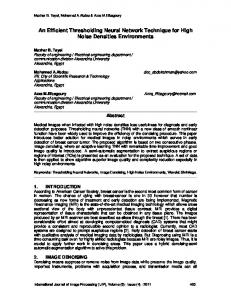
An improvement in the proposed technique can be achieved by incorporating golden data value. The input data to latches serves as golden data value as shown in Figure-3. Latch L1 and L2 helps to capture two data samples at rising edges of a single clock signal (CLK-A and CLK-B) which are 180 degree out of phase and has 50% duty signal. It is important to note that the clock signals are reduced from three to two and latches are reduced to only two for complete SEU and SET immunity. Golden Value Data
D
CLK-A
D
CLK-B
Q
L1
Majority Voter
Q
L2
Voter Fault Recovery Unit
fed into software simulator to analyse the behaviour of the circuit under SEUs/SETs. • A SEU simulator is designed to create a realistic scenario for the faults to be injected into circuit under test due to SEU. • The final step is to calculate Error. The circuit under test is introduced with SEU faults through SEU simulator. Figure-4 shows the process of error calculation. Let us take a case where line A has to be induced with an SEU. The line/node is assigned to one of the outputs of the simulator. The simulator assigns the original value on line A as fault-free value. A logic ‘1’ on the simulator output driving line A will invert the original value during simulation. This value is denoted as fault-value as shown in Figure-5.
Figure-3: The proposed scheme with reduced clock signals and latches Simulate
The proposed technique can be optimized for one clock signal as well for time critical applications. This optimization is achieved by capturing data sample at the rising and falling edge of the same clock. 4. MAJORITY VOTING LOGIC Majority voting is commonly used in TMR systems. The proposed mitigation technique is based upon simple majority voting. All the data samples which were stored at different time intervals are fed into majority voter circuitry. The data samples from ‘sample release stage’ are compared with each other. Data is considered ‘Fault Free’ if no disagreement is found. On the other hand, if disagreement is found, the data samples from the ‘sampling stage’ are considered to evaluate Fault Free output. 5. EXPERIMENTAL SETUP AND RESULTS We first elaborate the experimental flow which is incorporated for validating the proposed scheme. Then, we discuss the SEU simulator; we have developed to insert faults representing SEUs. We also discuss the functional testing procedure employed for accessing the SEU immunity of the proposed technique and, then we analyze the results by applying our unique technique. The experiment flow involves following steps: • The proposed technique is coded in ‘C’ programme, which takes VERILOG net-list of the circuit under test as input. VERILOG net-list are obtained through Synplify_ASIC software. D-flip-flops are identified and structural modifications are made to the original circuit by modifying the net-list. The modified net-list is then
Figure-4: Error evaluation of the proposed technique 6. RESULTS The Experimental results are derived for a medium sized circuit ISCAS89 benchmark circuits S386 contains 12 FlipFlops. We injected 1000 random SEU, SET faults,) to verify our proposed scheme. Faults were injected through SEU simulator. The proposed scheme can handle all the SEUs and SETs as well and enhances the system performance because no extra hardware/software is required for SET in the clock. It is important to note that the Mavis etal. [12] proposed a scheme which has 4 clock signals and 9 latches to give SEU immunity whereas our proposed scheme has only one two clocks and only two latches are required. There was no area or power analysis done for previous architecture to compare with the proposed scheme. So authors implemented the proposed technique and Mavis. et al technique on 0.13 um CMOS technology. Figure-5 illustrates the area calculation. Area saving of 59% is achieved for the circuit under test. Figure-8 shows approx 63% Power saving through proposed technique. The result clearly shows that our proposed scheme is much more efficient than other techniques. The scheme not only gives
Proceedings of the First NASA/ESA Conference on Adaptive Hardware and Systems (AHS'06) 0-7695-2614-4/06 $20.00 © 2006 IEEE
100% fault recovery from all single event faults but also from single event transients.
technique reduces the number of clock signals required for temporal sampling for SEU and SET immunity when compared with previously proposed schemes. The proposed technique was validated by injecting random SEU with the help of SEU simulator. The fault injection procedure was developed in Verilog, and reflects the effect of an SEU in a synchronous circuit. Experimental results show that 100% of the faults can be detected with minimum hardware required. The proposed technique can be employed in any commercial FPGA and reconfigurable SoC with minimum speed and area overhead. Power Consumption (mW) 0.06 0.05 0.04 0.03 0.02 0.01
Figure-5: Fault injection process of the designed SEU simulator
0 Mavis etal
Proposed Scheme
Figure-8: Power analysis
5000
11. REFERENCES
4500 4000 3500
[1] [2]
Area
3000 2500 2000 1500 1000 500 0 Mavis etal
Proposed Scheme
[3]
Figure 6: Area comparison Figure-7 presents area results in terms of total number of flipflops of 2x2, 8x8, and 16x16 bit multipliers, using no tolerance scheme (standard), TMR, Mavis et al. [12] scheme and the proposed scheme. Figure-7 shows that the scheme is efficient than previously proposed schemes. The proposed scheme has 33% saving interms of the total number of flipflops over standard TMR required for SEU immunity whereas 77% saving over Mavis etal.
[4]
[5]
[6]
[7] 350
Number of FFs
300
[8]
250
standard 200
TMR
150
Mavis etal
Proposed 100
[9]
50 0 2x2
8x8
16x16
Figure-7 Area Comparison of the proposed technique 7. CONCLUSION This paper has described a new concurrent SEU/SET mitigation technique for synchronous and reconfigurable architectures. The proposed scheme gives immunity against all single faults with auto correction mechanism. Due to this added feature, scrubbing is no longer required. This
[10] [11]
[12]
[13]
http://www.sti.nasa.gov/thesfrm1.htm K. Johansson, P. Dyreklev, B. Granbom, M.-C. Calvet, S. Fourtine, and O. Feuillatre, “In-Flight and Ground Testing of Single Event Upset Sensitivity in Static RAMs,” Accepted for publication IEEE Transactions on Nuclear Science E. Normand, “Single Event Upset at Ground Level,” IEEE Transactions on Nuclear Science, vol. 43, pp. 2742-2750, 1996. J. Olsen, P. E. Becher, P. B. Fynbo, P. Raaby, and J. Schultz, “Neutron-Induced Single Event Upsets in Static RAMS Observed at 10 km Flight Altitude,” IEEE Transactions on Nuclear Science, vol. 40, pp. 74-77, 1993. Peterson, E.L., "Single-Event Analysis and Prediction",IEEE Nuclear and Space Radiation Effects Conference Short Course Text, 1997. Massengill, L., "SEU Modeling and Prediction Techniques", IEEE Nuclear and Space Radiation Effects Conference Short Course Text, 1993. Lima, F., Carmichael, C., Fabula, J., Padovani, R., Reis, R., “A Fault Injection Analysis of Virtex® FPGA TMR Design Methodology”, Proc. of (RADECS), Sept. 2001. Carmichael, C., Fuller, E., Fabula, J., Lima, F., “Proton Testing of SEU Mitigation Methods for the Virtex FPGA”,Proc. of MAPLD, 2001. Dupont, D., Nicolaidis, M., Rohr, P., “Embedded Robustness IPs for Transient-Error-Free cs”, IEEE Design and Test of Computers, May-June, 2002. Lima, F., Carro, L., R., Reis, R., “Designing fault tolerant systems into SRAM-based FPGAs” DAC03 Lima, F. Carro, L., Reis, R., “Reducing Pin and Area overhead in Fault-Tolerant FPGA-based Designs” FPGA 2003, California USA. Mavis, D.G., Eaton, P., H, “SEU and SET mitigation techniques for FPGA circuit and configuration bit storage Design” MAPLD International conference Mavis, D., Eaton, H., “Temporally Redundant Latch for Preventing Single Event Disruptions in Squential Integrated Circuits”, tech report P8111.29, Mission Research Corporation, october 1998.
Proceedings of the First NASA/ESA Conference on Adaptive Hardware and Systems (AHS'06) 0-7695-2614-4/06 $20.00 © 2006 IEEE