Proceedings of COBEM 2005 Copyright © 2005 by ABCM
18th International Congress of Mechanical Engineering November 6-11, 2005, Ouro Preto, MG
AN ENVIRONMENT FOR TESTING AND SIMULATING ALGORITHMS FOR AUTONOMOUS STAR SENSORS Márcio Afonso Arimura Fialho∗ INPE – Instituto Nacional de Pesquisas Espaciais Av. dos Astronautas, 1758 – Jd. da Granja – CEP 12227-010 – São José dos Campos – SP – Brazil
[email protected]
Osamu Saotome ITA – Instituto Tecnológico de Aeronáutica Praça Mal. Eduardo Gomes, 50 – Vila das Acácias – CEP 12228-900 – São José dos Campos – SP – Brazil
[email protected]
Abstract. In this paper we describe a program written to evaluate algorithms used in the process of attitude determination, including image processing algorithms, star identification algorithms and attitude determination algorithms. This simulation environment allows the user to perform multiple tests, including Monte Carlo simulations at random locations and attitude determination from true sky images. The user can choose from a list of star identification algorithms and image processing algorithms which algorithms will be used during the tests. For example, the list of observed stars, that is used by the star identification algorithm, can be generated from a true-sky image saved previously in the hard-disk, a true-sky image downloaded from a camera in real-time or from the star catalog itself, depending on the image processing algorithm or sensor optical model algorithm chosen for the test. We successfully performed a true-sky demonstration with this software in October 2003. This software was written in C, using free development tools (DJGPP, RHIDE and ALLEGRO). It runs in any PC running MS-DOS or capable of running MS-DOS programs. The software is portable, so it can be compiled to other platforms, such as Windows and possibly Linux/Unix. Keywords: simulation, attitude determination, engineering tool. 1. Introduction For precise control of a spacecraft and fine pointing of scientific instruments, such as telescopes, a very accurate knowledge of a spacecraft's attitude (spatial orientation) is required. Many sensors can be used aboard a spacecraft for attitude determination, including sun sensors, horizon sensors, magnetometers, etc (Wertz, 1978). One of the most advanced technologies for attitude determination are the autonomous star sensors (also known as autonomous star trackers in the literature) (Eisenman, 1997). Basically, an autonomous star sensor is a computerized optical camera capable of attitude determination from the analysis of images it takes from the star field. The purpose of this paper is to describe briefly a program written by our research group to test and evaluate algorithms used in autonomous star sensors, and also the star sensors themselves. The program was named PTASE, a Portuguese acronym that stands for Programa de Testes de Algoritmos para Sensores de Estrelas, which translated to English would be "Test Program for Algorithms used in Star Sensors". PTASE started out as an end of course project of an undergraduate course in Electronic Engineering (Fialho, 2003). In Brazil, especially at INPE, other groups have worked with attitude determination using star trackers (Cabeza, 1997) and (Carvalho, 2001). (Carvalho, 2001) has written a software in Matlab (The MathWorks, Inc., 2005) intended to evaluate star identification algorithms used in autonomous star sensors. However we decided to write our own in C language. The main reasons for this decision was the fact that Matlab is an interpreted language, which means that programs written in Matlab are comparatively slower than programs written in a compiled language. Also, we wanted a platform where a closer implementation to the flight version of the algorithms to be used in a star tracker could be produced.
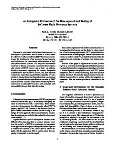
2. Attitude determination from a raw star field image: In Figure 1, the basic flow chart used by an autonomous star tracker in the process of attitude determination from a raw star field image is presented, when the observed stars aren’t known a priori (e.g., when a star sensor is in a true “lost in space” condition).
∗
Also a MSc. graduate student in Electronic Engineering at ITA - Instituto Tecnológico de Aeronáutica.
Figure 1 - Attitude determination from a star field image. The STAR FIELD IMAGE can be an image generated by an optoelectronic sensor (e.g. a CCD sensor or an APS sensor), a previously stored true-sky image or even an image generated by simulation. The SENSOR OPTICAL MODEL is an optical model for the optical head of a star sensor or a prototype camera. It stores information such as field of view (FOV), brightness sensitivity, coefficients of calibration functions, etc. The IMAGE PROCESSING ALGORITHM uses this information to convert pixel coordinates in the image to threedimensional (unit vector) coordinates in the star sensor (or prototype optical head) frame of reference. Also it computes the instrumental magnitudes for the observed stars from the measured pixel intensities, after subtracting the averaged dark signal intensity. It outputs a list of observed stars, containing their unit vectors in the star sensor frame of reference, their instrumental magnitudes and control flags. The star sensor frame of reference is a non-inertial frame, that may rotate, whose Z-axis is parallel to the optical axis of the sensor. The WORKING STAR CATALOG is a star catalog in a format suitable for the selected star ID algorithm, being optimized for small execution times. Depending on the star ID algorithm chosen, it can even be a catalog of star pairs that fit the FOV instead of a catalog of stars. By comparing the list of observed stars with the working star catalog the STAR ID ALGORITHM is able to identify the observed stars. – In star sensors, identification means discovering the observed star's coordinates in an inertial frame of reference (better explained in section 3.2) – Then the star ID algorithm outputs a list of identified stars, that is fed to an ATTITUDE DETERMINATION algorithm. By comparing the stars coordinates in the star sensor frame of reference to the same stars coordinates in an inertial frame of reference, the attitude determination algorithm is able to find out the relation between these two frames of reference, that is the star sensor attitude itself. Usually, the star sensor attitude is expressed as a rotation matrix or as a quaternion. When a previous attitude is known and the spacecraft (or the optical head of the camera) is still or very slowly rotating, the process of attitude determination can be simpler. Provided the spacecraft doesn't rotate more than a few pixels in relation to the previous attitude, no star re-identification will be required and the star sensor will have to image only small rectangles around the previously identified stars, instead of a full frame, reducing significantly the amount of image processing required. In this mode of operation, the star sensor will be basically tracking the previously identified stars in its optoelectronic matrix (hence the name star tracker for many star sensors). In a real application (e.g., a star sensor aboard a spacecraft), it's possible to determine the spacecraft attitude from the star sensor attitude through a simple rotation, because the star sensor is fixed in the spacecraft implying that the relation between the star sensor frame of reference and spacecraft frame is well known or can be precisely measured. 3. PTASE operation and internal workings: 3.1 - Program operation: The star catalog, used in simulations, is chosen at start-up time, and is specified as a parameter when calling the program from a DOS prompt. E.g., the command: PTASE CAT_M7.CAT will start the program with the star catalog stored in the file CAT_M7.CAT. After start-up the program displays a screen giving current video mode and environment. Pressing any key, the program main screen appears, as shown in Figure 2.
Proceedings of COBEM 2005 Copyright © 2005 by ABCM
18th International Congress of Mechanical Engineering November 6-11, 2005, Ouro Preto, MG
Figure 2 - PTASE main screen. Note: This screenshot was converted to a negative grayscale image to preserve printer ink.
As can be seen in this figure, PTASE simulates a star sensor, displaying in it's main screen what a star sensor would "see" if pointed to coordinates given in the field "Coordenadas do sensor". The user can change these coordinates using the arrow keys to move around, or using the 'E' and 'R' keys to roll, or by pressing 'F5' to open a dialog box where the simulated star sensor coordinates can be entered. By pressing the key 'F7' a dialog window appears, from where the user can select the star ID algorithm to be used in tests and simulations. If the algorithm is configurable, the button "Configurar" will be enabled. Clicking on this button a dialog window used to configure individual parameters of the star ID algorithm appears. The user can either accept the changes by pressing "OK" or dismiss by pressing "CANCELAR". Likewise, the star ID selection dialog window may be closed either by pressing "OK" or "CANCELAR". By pressing the key 'F6' it’s possible to select and configure an image processing algorithm or a sensor optical model algorithm, in a process very similar to that used for selecting and configuring star ID algorithms. The basic difference between an image processing algorithm and a sensor model algorithm is that the first generates the "list of observed stars" from an image, while the later generates this list from the working star catalog itself. There are two sensor model algorithms currently implemented: gen_sia_input and gen_sia_input2. The first is an ideal model, no noise and bias added to star positions and magnitudes. The second is a more realistic model, where magnitude limit and random noise (with normal distribution) in position and magnitude can be inserted. No option for selecting the attitude determination algorithm is provided, since in the current implementation, these are called as subroutines by the star identification algorithm. By pressing key '1', the selected image processing (or sensor optical model) algorithm and star ID algorithm are run. After their execution, the program displays the calculated attitude from the identified stars and the attitude determination error. However, the attitude determination error, which is a measure of the difference between the actual attitude and computed attitude, is meaningful only when the list of observed stars fed to the star ID algorithm is generated from the star catalog itself. Pressing the key '2' a Monte Carlo simulation is performed, using the currently selected sensor model algorithm (e.g., gen_sia_input or gen_sia_input2) and star ID algorithm. The number of runs in Monte Carlo simulations and the star sensor's Field of View length and height are configurable by pressing 'F8'. 'F10' displays the log file being generated by the program. This log file is used to store relevant information about the algorithms being tested in PTASE. A brief on-line help is available by pressing key 'F1'. To exit the program, the user press 'ESC'. 3.2. Catalog handling: The .CAT files are in a custom catalog file format, probably very similar to the formats used by star sensors for onboard storage. Their coordinates are represented using spherical coordinates, in the Hipparcos ICRF - International Celestial Reference Frame (ESA, 1997) and (IERS, 2005). Only fields that are used for attitude determination or debugging are stored. The stored fields are: right ascension, declination, instrumental magnitude, star ID numbers, flags and checksum. This custom format is suitable for storage, but not for fast processing, due to the large number of trigonometric functions involved to work with angular coordinates. Right ascension and declination are stored using a custom fixed-point format. At start-up, PTASE generates a working star catalog from the input .CAT file. The working star catalog is a catalog in a format optimized for fast processing that is used by the star ID algorithms in the process of star identification. Its format depends on the star ID algorithm chosen. It can be even a catalog of star pairs that fit the FOV (Field of View),
instead of a catalog of stars. However, at current development stage, all star ID algorithms implemented in PTASE belongs to the same family and share the same working star catalog. For this family of star ID algorithms, the working star catalog is a catalog of stars where each star is represented by a unit vector in the Hipparcos ICRF frame. The conversion from spherical coordinates (in the .CAT file) to Cartesian unit vector coordinates is given by the equations:
Rxi = cosα ⋅ cos δ R yi = sin α ⋅ cos δ Rzi = sin δ
(1) (2) (3)
where: Rxi , Ryi , Rzi = components of unit vector R representing the star, in the inertial frame of reference. α = ICRS right ascension. δ = ICRS declination. The conventions used for coordinate transformation are such that: - positive x-axis points to α = 0, δ = 0; - positive y-axis points to α = 90°, δ = 0; - positive z-axis points to δ = + 90° (north pole of ICRS) After these conversions, the coordinates are still in the Hipparcos ICRF frame or reference, whose origin is the Solar System barycenter. However, we need them in an "inertial" (non-rotating) reference frame whose origin is at the star sensor itself – PTASE intent is to simulate the operation of a star sensor –. For simplicity, we adopt a non-rotating reference frame whose axes are parallel to those of Hipparcos ICRF frame of reference. This frame of reference will be regarded as the star sensor inertial frame of reference, or inertial frame of reference for short, being opposed to the (rotating) star sensor of reference. To convert from the Hipparcos ICRF frame to the star sensor inertial frame, a number of effects must be considered, including stellar aberration, trigonometric parallax, gravitational effects, etc. However, for the accuracy of star sensors being studied in PTASE (in the order of few arc-seconds), that are located in the inner Solar System, only stellar aberration needs to be considered. This can be done by:
R' =
R + v ast / c R + v ast / c
(4)
where: R' = stellar unit vector coordinates in the star sensor inertial frame of reference. R = stellar unit vector coordinates in the Hipparcos ICRF frame of reference. vast = star sensor speed related to the Solar System center of mass, in the Hipparcos ICRF frame. c = speed of light in vacuum. For a star sensor fixed on Earth, |vast| will be very near the orbital speed of Earth, around 29.8 km/s or 0.0001 c. In this case, stellar aberration can account for an apparent displacement of stars up to 21 arc-seconds. Equation (4) was derived using the Newtonian Mechanics framework and some simplifying assumptions. A more precise formulation can be achieved in the Relativistic framework. However, for the accuracy required for typical star sensors, the remaining errors, if any, (in the order of few milliarcseconds, or even less) are completely negligible. Correction for aberration hasn't been implemented yet in PTASE, but we intend to implement it soon. Currently, the working star catalog stores only the stars unit vectors and their instrumental magnitudes. These values are stored using double precision floating point formats in PTASE. 3.3. Catalog preparation: PTASE comes with two additional programs, READCAT and PROC_CAT. READCAT parses the Hipparcos catalog (ESA, 2005), generating a subcatalog in the custom .CAT format, including all stars in the Hipparcos main catalog up to a limiting visual magnitude, specified by the user. While parsing, READCAT is able to convert visual magnitudes to instrumental magnitudes through an empirical formula that relates these magnitudes with B-V and V-I color indexes. Also, it permits the user to perform proper motion corrections from the Hipparcos mean epoch (J1991.25) to the mean mission epoch for a star sensor (e.g. J2010). Since all coordinates are given in the Hipparcos ICRF frame realization, which is independent from Earth movements, no corrections for Earth precession or nutation are required. However, READCAT doesn’t change the original order for stars that appears in the Hipparcos catalog, neither merges optically double or multiple systems. But the algorithms currently implemented in PTASE expect the catalog to
Proceedings of COBEM 2005 Copyright © 2005 by ABCM
18th International Congress of Mechanical Engineering November 6-11, 2005, Ouro Preto, MG
be sorted by instrumental magnitude and are more efficient if optically double or multiple systems are represented by a single equivalent star. Hence, the .CAT files generated by READCAT are processed by PROC_CAT, which merges optically double or multiple systems into a single photometrically equivalent star and rearranges the stars in order of increasing magnitude. Plus, PROC_CAT generates a log file. In this log file PROC_CAT writes a histogram of stars x magnitude and a detailed list of every star it wrote in the target .CAT file. This information is useful, for example, in the process of determining the memory requirements for storing a star catalog for a particular mission. 3.4. Field of view generation: Here we describe briefly the mathematical models used to generate the star field visualization (Figure 2) from the attitude of the simulated star tracker. Internally, the star sensor attitude can be expressed either through Euler angles or through a rotation matrix. From Euler angles (basically the right ascension, declination and twist angle), a rotation matrix M, that converts coordinates from the inertial reference frame to the star sensor reference frame can be computed, through:
− sα cφ − cα sδ sφ M = sα sφ − cα sδ cφ cα cδ
cα cφ − sα sδ sφ − cα sφ − sα sδ cφ sα cδ
cδ sφ cδ cφ sδ
(5)
Where: s and c are shorthand notations for sine and cosine, respectively. φ = twist or roll angle (zero when north is up; positive when sensor moves in clockwise direction (stars appears to have moved counter-clockwise)). α = optical axis right ascension. δ = optical axis declination. This rotation matrix is also known as the star sensor's attitude matrix. By pre-multiplying the star unit vectors in the inertial reference frame by the attitude matrix, we get their coordinates in the star sensor reference frame:
Rxs R = M ys Rzs
Rxi R yi Rzi
(6)
Equations (5) and (6) are valid if the following conventions are observed: Rzs = the star unit vector component in the star sensor optical axis. Rxs and Rys = star unit vector components in the optical plane of the star sensor. Star sensor axes {xs, ys, zs} forms an orthogonal right-handed system. Rx , Ry and Rz are the star unit vector components in the inertial reference frame. Hence, by using this equation, it's possible to obtain the star location in relation to the star sensor from the star catalog loaded in PTASE, where stars are mapped in a non-rotating, inertial frame of reference. From the computed star coordinates expressed in the star sensor frame of reference, PTASE is able to know if these stars should be plotted or not on screen, and where to plot them. Since Eq. (6) would have to be computed for every star in the catalog to determine their location in relation to the star sensor axis, PTASE uses a clever idea to enhance its execution speed when replotting the star field in the simulated star sensor FOV (Figure 2). Taking a closer look at Eq. (6), we realize that the program needs to compute only the Rzs component of the stars to know if they have a chance to be visible in the star sensor's FOV. Let θ be the FOV diagonal angular length (e.g., for a FOV of 20° x 20° θ will be around 28°). If the star Rzs component is smaller than cos(θ / 2) then for sure its outside the simulated star sensor FOV and will not appear on the screen. Hence, no further processing is required. Otherwise, PTASE computes Rxs, Rys and performs further processing to check if the star really needs to be plotted, but these are just a very small number in comparison to the total number of stars in the catalog. To speed up execution times, PTASE works internally with angles in radians and magnitudes in the natural logarithm of brightness instead of conventional magnitudes. However all the data saved on log files and displayed to the user is expressed in conventional units (degrees, arc-seconds and conventional magnitudes).
3.5. Star identification algorithm Currently, four versions of a star identification algorithm are implemented in PTASE. The star ID algorithm implemented in PTASE was first described in (Fialho, 2003). Basically, it can be described as a two step algorithm. In the first step it tries to match a triangle of observed stars (the three brightest stars above a minimum magnitude and with a minimum angular distance) with a triangle of catalogued stars. This step uses lists (or vectors) of candidate stars for each star in the observed triangle. A similar algorithm in this aspect is the algorithm described by Baldini et. al (Baldini, 1993). When a triplet of stars from the catalog matches the observed star triangle, the algorithm jumps to the second step, where an estimated attitude from this matching is computed and the remaining stars in the FOV are matched through a direct match technique. If the number of stars matched in this step is greater than a minimum threshold (e.g, half the number of observed stars), then the identification is accepted as correct. Otherwise, the triplet found in the catalog is probably the wrong one, so the algorithm traces back to the previous step and continues to search for another triplet of catalogued stars that may match the observed star triangle. Since the last report in 2003, the following improvements have been done in this algorithm: - The vectors of candidate stars for the stars of the observed star triangle are assembled in an optimized way, leading to an average speed improvement of 23% in relation to the basic algorithm. - It's possible to use attitude estimates to speed up the search process, by including in the vectors of candidate stars only stars within a specified distance from an estimated optical axis pointing direction. - The algorithm is able to withstand fake stars or spikes in the star sensor's FOV. When it's not possible to get a successful identification with the chosen observed star triangle, the algorithm attempts identification with another triangle of observed stars. - The algorithm returns the mean and variance for the identified stars magnitude errors. These values can be used with an algorithm described in (Fialho, 2005) for automatic calibration of magnitude offset and tolerances in autonomous star sensors. Even though only this star ID algorithm has been implemented in PTASE, PTASE allows the implementation of other star ID algorithms. Two attitude determination algorithms have been implemented in PTASE. The first one is a deterministic algorithm that computes the attitude from two vector observations (in this case, the star unit vectors). The second is an algorithm based on the least squares method, that computes the best attitude estimate for a given number of vector observations (Shuster, 1989) and (Carvalho, 2001). The result from the deterministic algorithm is used to seed the least square attitude determination algorithm. In the current implementation, these algorithms are called as subroutines of the star ID algorithm. 4. Simulations In this section the most significant results obtained with PTASE are presented: Table 1 shows a typical simulation used to evaluate a star ID algorithm. Listed in this table are the result of a Monte Carlo simulation, employing a star sensor optics model algorithm and a star ID algorithm. The star sensor optics model algorithm used in this simulation generated a list of observed stars from the same star catalog used by the star ID algorithm, by introducing a random error (with a normal distribution) in stellar positions and magnitudes. Their standard deviations were: 3 arc-seconds per axis (4.2 ” total), and 0.25 magnitude in stellar magnitudes. The tolerances used for the star ID algorithm were adjusted empirically, in such a way to give the fastest execution time but without sacrificing too much the success rate.
simulation number 2 4 5 7 9 mean
Table 1 - Execution times and success rates for simulation. execution time for mean twist (roll) mean attitude 1000 runs per success rate angle error ( ε φ ) error ( ε att ) simulation 24.88 s 22.69 s 24.33 s 23.73 s 24.66 s (24.06 ± 0.84) s
99.4 % 98.8 % 99.3 % 99.0 % 99.1 % (99.12 ± 0.25) %
6.48 ” 7.02 ” 6.70 ” 6.82 ” 6.83 ” (6.77 ± 0.19) ”
4.48 ” 4.88 ” 4.64 ” 4.72 ” 4.73 ” (4.69 ± 0.14) ”
mean error in the sensor optical axis direction ( ε axis ) 0.95 ” 0.96 ” 0.97 ” 0.97 ” 0.96 ” (0.962 ± 0.013) ”
Where: 1" = 1 arc-second = 4.848 µrad = 1/60 arc-minute = 1/3600 degree. This simulation was run in a MS-DOS prompt under Windows 98, by a PC with a 450 MHz processor. The simulated field of view was 20° x 20° This simulation was performed with alg_ide_mf1_2 on December 18th, 2003. alg_ide_mf1_2 is an enhanced version of the algorithm described in (Fialho, 2003). It includes the ability to assemble the candidate star lists in an optimized way, and is able to use attitude estimatives to speed up the identification process. However, it cannot cope with false stars, nor returns the observed errors in the magnitude of identified stars. The latest version of this family of star ID algorithms is alg_ide_mf1_4.
Proceedings of COBEM 2005 Copyright © 2005 by ABCM
18th International Congress of Mechanical Engineering November 6-11, 2005, Ouro Preto, MG
From these 24 seconds used to run 1000 times the star ID algorithm and the star sensor model algorithm (gen_sia_input2), around 9 seconds have been spent by gen_sia_input2. Hence, on average, the star ID algorithm took 15 milliseconds to perform stellar identification. The failures listed in the table where caused by the star ID algorithm not being able to identify the stars in the list of observed stars, not by star misidentification. In this simulation, attitude determinations from misidentified stars would be counted as successful ones, even when they were completely wrong. The reason for this is the fact that a star sensor has no means to know for sure if the attitude it determined is fine or resulted from stellar misidentification. A few failures in attitude determination isn't too much a problem, since it will add just a little more delay for the first attitude determination. However an incorrect attitude determination is much worse, since it can lead the spacecraft to reorient itself in a dangerous manner if it's not properly safeguarded, which in turn may jeopardize the spacecraft. Fortunately, in our simulations, our star ID algorithm has proved to be reasonably safe. In more than 10,000 runs, no incorrect attitude determination has occurred (For practical purposes, we have defined an incorrect attitude when the attitude error is greater than ten arc minutes (2.9 milliradians)). For every simulation, a histogram for attitude error was generated and saved in the log file. The errors displayed in table 1 have been computed with the following equations:
ε att = M true − M est
(7)
ε axis = Z ast − Z ast _ est
(8)
ε φ = φ true − φ est
(9)
Where, for each run: εatt = measured attitude error. Mtrue = star sensor attitude provided for gen_sia_input2, regarded as the true star sensor attitude at each run. Mest = star sensor attitude estimated by the star ID algorithm and attitude determination algorithm, from the list of observed stars. εaxis = measured error in the determination of the line of sight for the star sensor. Zast = unit vector for the star sensor line of sight (or optical axis) direction during the run. Zast_est = estimated value for Zast by the star ID algorithm and attitude determination algorithm. εφ = measured error in roll angle. φtrue and φest = true and estimated roll angles, respectively. Table 2 shows the result of a test performed with true-sky images on October 2nd, 2003. In this test, a prototype camera was attached to a PC running PTASE. The user could command from PTASE the acquisition and processing of an image taken from the camera, almost at real time. In this test, the camera was held still on the ground, pointing near the zenith, hence the camera was spinning with the same rotational speed of the Earth. The camera's field of view was 7.86° x 7.87°. It employed a CMOS-APS sensor with 1024x1024 pixels. Table 2 - Attitude determination by PTASE from true sky images (extracted from (Fialho, 2003), page 75). Computed attitude Test number Acquisition time right ascension declination twist angle (roll) 1 19:55:22 -49.3924° -41.2645° -27.7198° 2 20:01:56 -47.7314° -41.2536° -27.6915° 3 20:07:00 -46.4740° -41.2615° -27.7256° 4 20:11:30 -45.3511° -41.2633° -27.7296° As can be seen, on average, the right ascension increases steadily, while the declination and twist angle remains practically the same. Plus, the observed rate at which right ascension increases is very close to the rate at which the Earth spins (0.2507 degrees per minute). After data reduction, it was found that the random error magnitude in attitude determination was around 40 arc-seconds to 1 arc-minute, a very bad value, especially for a narrow field of view camera. This bad result is in part explained by the fact that we have used uncalibrated optics. Plus, the site where the test was performed was close to heavy machines, perhaps causing the camera to vibrate. In addition to these errors, these values are affected by stellar aberration and other systematic errors caused by atmospheric conditions. In that day, we have performed many successful attitude determinations from true-sky images. No failures or misidentifications have occurred out of 18 attempts. The sky was very clear and dark that night.
5. Program development PTASE was written entirely with open-source tools. To compile the sources, we have adopted DJGPP (Delorie, 2005), a MS-DOS port of the famous GCC compiler. The sources were edited in RHIDE (Höhne, 2003), a free DJGPP integrated development environment, very similar to Borland's Turbo C++ 3.0 in look and feel. Finally, the entire graphical interface to the user was based on the ALLEGRO Game Programming Library (Hargreaves et al, 2005), a free, multi-platform library. At the time of writing this paper, RHIDE and Allegro could also be found with DJGPP at http://www.delorie.com/djgpp. 6. Conclusions In this paper we have described a C/C++ program named PTASE, written for simulating and testing algorithms used in the process of attitude determination by autonomous star trackers, including image processing algorithms, star identification algorithms and attitude determination algorithms. The basic flowchart for attitude determination, the principal mathematical relations and the most important optimizations behind PTASE have been presented and discussed. Results from simulations and a series of successful attitude determination from true sky images, using PTASE have been presented, proving that PTASE can be used either as a tool for testing star identification algorithms, through long Monte Carlo simulations, or testing a whole attitude determination system, employing true-sky images, previously stored or acquired on real time. Finally, the tools used for the development of this software have been cited to the interested reader. Readers interested in obtaining a copy of PTASE should contact the authors. 7. Acknowledgments We wish to thank all the reviewers of this article, for their suggestions and patience in reading it. We wish also to thank prof. Frascino, Prof. Zividani and all the COBEM staff for organizing the COBEM Congress, thus providing a great opportunity for sharing ideas and promoting science and technology development in the South America. This work was sponsored by the Brazilian Government through CNPq, MCT/INPE and CTA/ITA. 8. References Baldini, D. et al., 1993, “A new star-constellation matching algorithm for satellite attitude determination”. ESA Journal, v. 17, n.2, p. 185-198. Cabeza, J. M., 1997, “Um Sensor Estelar para o Apontamento Fino do Telescópio Masco”. Master Thesis, (INPE-6682TDI/627). Carvalho, G. B., 2001, “Levantamento de Técnicas de Identificação de Estrelas e Desenvolvimento de um Ambiente de Simulação e Testes para Análise de seus Desempenhos em Aplicações Espaciais”. Master Thesis, (INPE-8307TDI/766). Delorie, DJ et al., 2005, “DJGPP - A free 32-bit development system for DOS”, http://www.delorie.com/ Eisenman, A. R., Liebe, C. C. and Jørgensen, J.L., 1997, “The new generation of autonomous star trackers”, SPIE Vol. 3221. p. 524-535. ESA, 1997, “The Hipparcos and Tycho Catalogues” Vol. 1, section 1.2, ESA SP-1200 ESA, 2005, “The Hipparcos Space Astrometry Mission”, http://www.rssd.esa.int/Hipparcos/ Fialho, M. A. A., 2003, “Ambiente de Simulações e Testes de Algoritmos para Sensores de Estrelas Autônomos”, Undergraduate Work in Electronic Engineering, ITA - Instituto Tecnológico de Aeronáutica, São José dos Campos Brazil. Fialho, M. A. A., Lopes, R.V.F, Saotome, O., 2005, “Um Método de Calibração Automática em Magnitude para Sensores de Estrelas”. Anais do IV Congresso Temático de Dinâmica, Controle e Aplicações, DINCON'2005. p. 526-535. Bauru, SP, Brasil. Hargreaves, S. et al, 2005, “Allegro: A game programming library”, http://alleg.sourceforge.net/ Höhne, R. et al., “RHIDE - an IDE for DJGPP and other GNU based systems”, http://www.rhide.com/ IERS, 2005, “The International Celestial Reference System (ICRS)”, http://www.iers.org/iers/products/icrs/ Shuster, M. D., 1989, “Introduction to spacecraft attitude determination”. Laurel, MD: The Johns Hopkins University. The MathWorks, Inc. 2005, “Matlab and Simulink Technical Computing”, http://www.mathworks.com/ Wertz, J. R., 1978, “Spacecraft Attitude Determination and Control”, D. Reidel Publishing Company, Dordrecht Holland. 9. Responsibility notice The authors are the only responsible for the printed material included in this paper.