An Event-Driven Sensor Architecture for Low Power Wearables Henk Muller Cliff Randell Department of Computer Science, University of Bristol, UK.
[email protected], http://wearables.cs.bris.ac.uk/
ABSTRACT
In this paper we define a software architecture for low power wearable computers. The architecture is event driven, and is designed so that application programs have access to sensor data without the need for polling. The software architecture is designed to allow for an underlying hardware architecture that can achieve maximal power efficiency by switching off parts of the hardware that are known not to be required. INTRODUCTION
Wearable Computing places particular demands on software. It is characterised by having to accommodate a potentially large number of input devices which are simultaneously providing contextual data; a need to minimise processor activity to reduce battery consumption [1]; and the requirement for simplicity to aid debugging applications which may be used in adverse conditions. As a result of our experiences with software which had none of the above features, we have developed an eventdriven sensor architecture and used it successfully for several applications. BACKGROUND AND RELATED WORK
The Bristol Wearable Computing Initiative, established in 1997, initially carried out research on location based applications [2]. A software architecture was designed which continuously monitored the context of the user - location and personal interests - and attempted to match this to a database of media objects with associated attributes. The software was tested on our ’CyberJacket’ equipped with a CardPC, dGPS, speech recognition, headphones and a hand-held display. This architecture resulted in unnecessary processor activity when there were no matching media objects to be rendered, and hence wasted battery energy. It also became onerous to debug the application - particularly when muliple matches were obtained. In response to our early experiences we moved to an event driven architecture [3] and immediately found improvements in ease of design and longer battery life. We are continuing to develop this architecture using simulation in the main processor, and by adding processing capability to our sensors.
GPS receiver other sensors Heart Rate monitor
GPS Device driver
Stream
of pos
itions
other drivers Heart rate monitor Device Driver
Application Programs Stream
e data
of puls
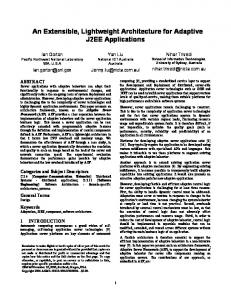
Figure 1. Traditional event driven architecture.
A similar architecture has been developed at the Nokia Research Center with the emphasis on the dynamic connection between wearable computers [4]. EVENT DRIVEN ARCHITECTURE
A traditional event driven architecture is shown in Figure 1. At the edge of the architecture we find the sensors of our wearable computer. As a running example we assume that we have four types of sensor: a GPS position sensor (obtaining continuous position data), a time sensor (telling us the exact time), a heart rate monitor (measuring the wearer’s heart rate) and a pinger (a sensor which may receive a “ping” signal generated by an external object). Most, but not all, of these sensors would normally generate a continuous data stream. The default NMEA GPS interface produces a series of positions, the clock produces a series of clock ticks. The exception here is the pinger, which will only generate a signal when a “ping” is detected. The first operation that any application program will perform on the sensor data is to filter the input streams for interesting events. For example, the heart rate monitor may be filtered by a health-monitor application to detect whether the heart rate goes above a certain threshold (say 100), or below a threshold (40), and page a doctor for assistance. Most application programs will, in a polling loop, monitor one or more sensors, and wait for some situation to happen, and take some action. We propose to lift this polling behaviour away from the application program, and move it nearer to the sensors. Each sensor will have two activities associated with it: a filtering activity, which will poll the sensor, and send an signal when something interesting happens, and an event list han-
dler, which will receive the signal, check the event list, and signal the main event loop about any events that need to be handled. Lifting the polling loop from the main application programme has two advantages. First, we can usually power down everything but the sensors; and, secondly, we present a better software environment for the design and maintenance of applications. We will discuss this behaviour first in terms of the heart rate monitor, and then show how it fits with the GPS sensor. After that we will show that the implementation of this can be made such that the wearable goes in a quiescent state when nothing is happening. Event driven heart rate monitor
The heart rate monitor will consist of three activities. First, there is the physical heart rate monitor, which integrates heart beats over a minute, and continuously delivers a signal as to the heart rate over, say, the last 15 seconds. The second activity is the filtering process. This filter will take the stream of heart data, and ignore it for as long as the heart rate is bounded by and , where and are set by the third process. The third activity, the heart-rate-list-manager, will maintain a list of events that application programs have subscribed to. If we assume that one application program that our wearable runs is an emergency monitor watching out for a cardiac arrest, then this emergency monitor would require an event “Heart rate less than 5 bpm”. A personal training application will have an event “Heart rate more than 170 bpm”. Based on which events applications are interested in, and on the current sensor output, the heart-rate-list-manager can program the and to only send a signal if the heart rate is below 5 or above 170. Indeed, it can deal with any number of events in the event list, and find a range of values which can be ignored, and only when the heart rate rises above a certain level, or below another level, need one or more application programs to be woken up to deal with the situation. For example, suppose that the heart rate goes up to 171, the training program will be woken up and will tell the user that she is going to strain herself. It can then set an event “Heart rate outside the range 170–180”. This will cause the heart rate filter to change its values of and to 180 and 170, so the application will be informed of the wearer actually going over the top, or slowing down again.
L
L
H
L
H
H
H
L
GPS
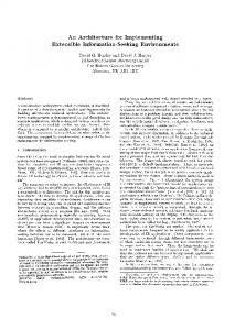
GPS data will use the same architecture on different data. The filtering process will ignore any data until the wearer has left a certain area. An easy way to define the area is the centre and radius of a circle. The GPS-event-manager will have a list of areas of interest, and will, based on the GPS position, calculate a circle with maximum radius in which the wearer can roam without straying in any interesting area. Figure 2 shows this. As long
Pub Museum
Pub Wearer’s current position Area where GPS can stay quiet
Figure 2. GPS events
as the user stays away from the Museum and the Pub, there is no reason to alert the user. The interface for the GPS sensor is hence: “Event when GPS position is within this distance of this point”. The GPSevent manager calculates an area of interest around the current position, which is posted to the GPS-filter to keep quiet until the wearer has left this area. Other Sensors
Our ’pinger’ device is a RF transmitter which generates a coded IP address and reference type number every five seconds. Pingers are placed in strategic locations, on objects, or on people; each of which have related information at the IP address. When our wearable computer detects a ’ping’ it is filtered to check if we are interested in it’s type and an event generated e.g.web pages designed for tourists can be displayed when we are in an unfamiliar location. Time has been implemented like this for years - called an alarm clock! - and can be combined with other sensors (see below). Sensor Event Fusion
The event manager maintains the overall picture. It dispatches events to processes that are waiting for them, but it may also implement cross sensor events. For example, it could wake an application if between 5 and 6 we are near a certain area (Happy hour at the bar). Cross sensor events are a conjunction or disjunction of single events. In order to handle them, the event manager requests events for all individual sensors. In this case, it will request the timer to generate an event “between 5 and 6”, and the pinger to generate an event “near the pub”. When either of them responds, that sensor is asked for the associated NOT-event; for example if the timer responds, the event manager will reduce the cross sensor event to “near the pub”, and insert an event “before 5 or after 6” in the timer queue. If a pub is spotted before 6, the cross-sensor event is passed to the application. If it becomes 6 before a pub is spotted the cross-sensor event is set back to its original “Between 5 and 6” and “Near the pub”. This style of event fusion reduces the amount of programming needed, and avoids application programmers having to write polling code.
Pinger Receiver Real Time Clock
|x-C|T
Clock Filter
Heart rate Event Manager
... ...
Application Program
Processor
GPS Receiver
L