Email: {johannes.wuethrich,alexios.balatsoukas,andreas.burg}@epfl.ch. AbstractâIn this paper ... frame error rate (FER) of a specific polar code is via extensive.
An FPGA-based Accelerator for Rapid Simulation of SC Decoding of Polar Codes Johannes W¨uthrich, Alexios Balatsoukas-Stimming, and Andreas Burg Telecommunications Circuits Laboratory, ´ Ecole Polytechnique F´ed´erale de Lausanne, Switzerland Email: {johannes.wuethrich,alexios.balatsoukas,andreas.burg}@epfl.ch Abstract—In this paper we present an FPGA-based system for rapid frame error rate simulations of successive cancellation decoding of polar codes. Our system is implemented on a Xilinx Virtex-7 XC7VX485T FPGA and it supports polar codes of any rate and of blocklength up to N = 1024 bits on that device. The supported simulation speed with N = 1024 is 108 codewords per second at a frequency of 100 MHz. The key idea that enables this high throughput is that the feedback part of the successive cancellation decoder can be ignored when evaluating the frame error rate. Thus, we can implement a heavily parallelized and deeply pipelined SC decoder which can output one decoded codeword per cycle. Moreover, the random input required to perform Monte Carlo simulations of the decoder is generated onchip by means of free-running XOR-based true random number generators at a rate of approximately 1 Terasamples per second.
I.
I NTRODUCTION
Polar codes [1] are channel codes which can provably achieve the capacity of various communications channels. Moreover, they have an efficient successive cancellation (SC) decoding algorithm whose complexity scales like N log N , where N is the blocklength of the code. It is know that polar codes do not exhibit an error floor when decoded using the SC algorithm [2]. This makes them attractive candidates for applications where very low error rates are required, such as high-speed communications links and storage applications. For the binary erasure channel, there exist tight upper and lower bounds for the frame error rate of polar codes under SC decoding, which can be evaluated numerically in a very efficient fashion [3]. However, for all other types of channels such bounds are not yet known and the only way to evaluate the frame error rate (FER) of a specific polar code is via extensive Monte Carlo simulations. Even though the complexity of the SC algorithm is relatively low, it is still a computationally challenging task to simulate frame error rates on the order of, e.g., 10−12 , using standard software SC decoders, even when they are heavily optimized. Contributions: In this work, we present an FPGA-based system that specifically aims at the high-speed simulation of polar codes. We achieve a throughput of 108 codewords per second by exploiting the fact that the feedback part of the SC decoder can be ignored in the evaluation of the FER. Moreover, as the soft-inputs of the SC decoder need to be generated at extremely high rates on the order of 1 Terasample per second, we propose to address the problem of stimuli generation with on-chip true random number generators (TRNGs).
Outline: In Section II we will briefly introduce the basic SC decoding algorithm and we explain why the internal feedback of the SC decoder does not influence the frame error rate (FER) and can therefore be ignored. We then give a detailed description of the implemented system in Section IV, focusing on the FPGA specific implementation choices. In Section V, we present the implementation results of our system on a Xilinx Virtex-7 FPGA and Section VI concludes this paper. II.
BACKGROUND
A. Polar Coding A polar encoder with a block size of N = 2n takes N input bits, denoted by uN 1 , and encodes them into N codeword bits, denoted by xN 1 , through the following linear transformation � � 1 0 N N N ⊗n x1 = u1 GN = u1 F , F = , (1) 1 1 where ⊗ denotes the Kronecker product. Due to this linear transformation, the bits of uN 1 experience virtual transmission channels of varying qualities. A polar code of rate R , K N is constructed by choosing uA freely, where A denotes the set of indices corresponding to the K best virtual channels, and freezing the remaining bits to zero. At the receiver, a noisy N observation of xN 1 is received, which we denote by y1 . If we assume that the transmission channel is an AWGN channel and that a binary antipodal modulation is used, we have yi = (1 − 2xi ) + ni ,
ni ∼ N (0, σ 2 ).
(2)
B. Successive Cancellation Decoding The SC algorithm decodes the bits in a successive order, meaning that each bit u ˆi is determined using the received values y1N and the previously decoded bits u ˆi−1 1 . For each bit a log-likelihood ratio (LLR) is calculated given by � � W (y1N , u ˆi−1 1 |ui = 0) LLRi = log . (3) W (y1N , u ˆi−1 1 |ui = 1) Using LLRi the bit value u ˆi is then decided using the following function 0, LLRi ≥ 0 and i ∈ A, u ˆi = h(LLRi ) = 1, LLRi < 0 and i ∈ A, (4) 0, i ∈ Ac .
û1
h
û2
h
LLR1
LLR2
f
f
f
LLRy1
f
f
LLRy2
f
g
f
LLRy3
g
g
f
LLRy4
LLRy5
g û1
û3
h
û4
h
LLR3
LLR4
û1 + û2 û3
û5
h
û6
h
LLR5
LLR6
û2
f
f
g
g
f
g
û1 + û2 + û3 + û4 û5
û7
h
û8
h
LLR7
LLR8
f
g
g
g
g û5 + û6
û7
Fig. 1.
LLRy6 û2 + û4 LLRy7 û3 + û4
g û6
LLRy8 û4
The SC decoding graph for N = 8. Fig. 2.
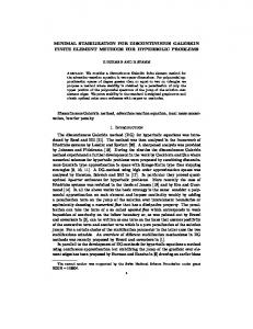
The LLR value for each received channel observation is � � W (yi |xi = 0) LLRyi = log . (5) W (yi |xi = 1) The decision LLRs (i.e., LLRi ) can be calculated from the received LLRs (i.e., LLRyi ) using a butterfly-based computation graph containing N log N nodes. An example for N = 8 is shown in Fig. 1. This graph contains two types of nodes, which are commonly called f and g nodes. Both types of nodes calculate a new LLR value Lo based on two input LLR values, denoted by L1 and L2 . A g node further takes as a third argument a partial sum u ˆs , which is a modulo-2 sum of a subset of the previously decoded codeword bits1 . This partial sum represents the decision feedback within the SC decoder. Due to complexity considerations, hardware implementations of the g and f functions usually employ the min-sum (MS) approximation [5], which is given by f (L1 , L2 ) = sign(L1 )sign(L2 ) min(|L1 |, |L2 |), u ˆs
g(L1 , L2 , u ˆs ) = (−1) L1 + L2 . III.
(6) (7)
P SEUDO -SC D ECODER
In this section, we summarize two observations which allow us to simplify and highly parallelize the SC decoder for the purpose of simulating the FER. Observation 1. The FER is independent of the transmitted codeword (see, e.g., [6]). It only depends on the channel used and on the choice of the frozen bit indices. Observation 2. In order to evaluate the FER of the SC decoder, the decision feedback within the SC decoder can be ignored. More specifically, using the values uN 1 to calculate the partial sums instead of the decision values u ˆN 1 yields identical FERs [1]. 1 The computation of the partial sums is not discussed further in this paper, as we will show that we can ignore them for our approach. For a detailed definition of the partial sums see, e.g., [4].
Top-level block diagram of the FPGA-based accelerator.
In order to see this, let us assume that all the bits up to l ∈ {1, . . . , N }, have been decoded correctly. Therefore, the partial sums required to decode ul+1 can be calculated either with ul1 or with u ˆl1 , since ul1 = u ˆl1 by assumption. If ul+1 is decoded incorrectly, a frame error occurs. As the SC decoder decodes bits in a strictly increasing order, this wrong decision can not be undone by any later action. The decoded values of bits ui , i = l +2, . . . , N, are irrelevant in this case, as a single erroneous bit decision renders the entire frame erroneous.2 Due to Observation 1, we can safely assume that the allzero codeword is always transmitted, without loss of generality. By combining this choice with Observation 2, we see that all partial sums become equal to 0. Thus, the g node update is simplified from (7) to gs (L1 , L2 ) = L1 + L2 .
(8)
As the g node update no longer depends on the previously decoded bits, it becomes possible to “decode” all bits in parallel. IV.
S YSTEM D ESCRIPTION
The general strategy for the simulation follows the wellknown principle of a Monte Carlo simulation. We randomly generate input data, representing the values received after being sent through the channel. In our case all this data should represent an all 0 code word, but with added white Gaussian noise, due to the channel. We then decode the data received and compare decoded bit values to 0. If one of the decoded bits in a frame is not 0 we count the frame as an error frame. At the same time, we count the total number of simulated frames. For the sake of simplicity, we focus on the simulation process itself and only show data treatment and ignore the 2 This is evidently only true for the frame error rate. The bit error rate can not be simulated in such a manner as the wrong decision for ul+1 could influence the decision of the bits ui , i = l + 2, . . . , N .
tails of the Gaussian distribution accurately, we propose to generate the corresponding (quantized) LLRs directly on-chip. By definition of the AWGN channel we have −(yi −1)2 1 √ e 2σ2 , σ 2π −(yi +1)2 1 W (yi |xi = 1) = √ e 2σ2 . σ 2π Using (5), it can be shown that
W (yi |xi = 0) =
(9) (10)
2yi , (11) σ2 meaning that, due to the all-zero codeword assumption, the LLRs of the received values follow a normal distribution LLRyi ∼ N (2/σ 2 , 4/σ 2 ). We choose to first generate uniformly distributed random values and then transform them into normally distributed values via look-up tables (LUTs), as there exist efficient circuit-level techniques to generate uniformly distributed random values. LLRyi =
Fig. 3.
Block diagram of the pseudo-SC decoder for N = 8.
control signals. The implemented simulator is packed as an IP core which provides an AXI-4 lite bus interface for the connection with a MicroBlaze soft-processor. The MicroBlaze processor is also implemented on the same FPGA and it is in charge of controlling the simulation process. The FPGA-based accelerator is connected to a PC through an RS-232 serial port. The channel definitions and the code definitions (N and A) are sent from the PC to the FPGA to configure the simulation runs. The FER results of the simulations are then sent back to the PC for post-processing. In the sequel, we give a more detailed description of the simulator part. In Fig. 2 we can see the general structure of the Monte Carlo simulation pipeline from top to bottom. We start by randomly generating the input LLRs. The input LLRs are then used to decode the corresponding codeword using the pseudo-SC decoder. Finally, the output bits of the pseudo-SC decoder corresponding to information indices are compared to the expected value of 0 to deduce whether a frame error occurred or not. A. Pseudo-SC Decoder Hardware Implementation The pseudo-SC decoder consists of n , log N pipeline stages, each containing N/2 f nodes and N/2 g nodes. We therefore obtain one decoded frame per clock cycle and a latency of n cycles. The f and g nodes are standard implementations of the corresponding min-sum approximation formulas given in (8) and (7). All LLRs are represented in sign-magnitude form using Q bits. We present an example of the decoder structure for N = 8 in Fig. 3. The decision LLRs obtained at the output of the n-th pipeline stage are passed to the H function block, which implements the decision function given in (4). B. Input LLR Generation Instead of generating the noisy observations yi , where significant care needs to be taken in order to represent the
We use uniform quantization with quantization step ∆ = 1 for the LLRs. All LLRs are represented with a sign-magnitude representation using Q quantization bits. Let L denote the set of possible LLR values with |l| < 2Q−1 , ∀l ∈ L. Let R be the set of all possible uniformly generated non-negative integer random values with 0 ≤ x < 2U , ∀x ∈ R, with U being the number of uniform random input bits for each channel. Each of the values in R is then mapped to a value in L by means of a function M : R 7→ L in such a way that the relative frequency � of appearances of any li ∈ L follows Nd 2/σ 2 , 4/σ 2 , where Nd denotes the discrete Gaussian distribution. In hardware, we implement the uniform random generation as true random number generators (TRNGs) based on XOR ring oscillators [7]. TRNGs have the advantage over pseudorandom number generators (PRNGs) that they do not need to be seeded and they do not show any periodicity (a PRNG implemented as a feedback shift register using P bits will cycle after generating 2P values). As we will generate a large amount of LLR values such a PRNG would need to be reseeded periodically to avoid correlation effects due to the periodicity. The disadvantage of using the cited TRNG is the energy consumption. Since it consist of free running ring oscillators, the switching frequency lies in the order of GHz and the energy consumption is substantial. The uniform-to-normal transformation as described above is implemented using block RAM (BRAM) based look-up tables. This allows for the uniform-to-random mapping to be dynamically reconfigured, by reprogramming the BRAM blocks, enabling the simulation of any desired SNR point. We found that using BRAMs for this task is the most efficient way of implementing the transformation, both in terms of speed and area used, compared to a transformation implemented with logic gates. C. Frame Error Counter The last part of the simulator system is the frame error counter. We simply compare the decoded bits, given by the H function, to 0. If not all bits are 0 we have a frame error and thus we increment the counter. We also have a separate counter counting the simulated frames. The resulting FER is
TABLE I.
FPGA IMPLEMENTATION RESULTS 0
Slice LUTs Slice Registers BRAMs
Available 303, 600 607, 200 1, 030
Total Utilization 113, 018(37.2%) 75, 756(12.5%) 273(26.5%)
10
SC & TRNG 111, 277(36.6%) 74, 223(12.2)% 257(24.9%)
−2
10
−4
given by the fraction of the numbers obtained by those two counters. All counters in the system are implemented using 64 bits.
FER
10
−6
10
−8
10
V.
Rate: 0.5 Rate: 0.4 Rate: 0.3 Rate: 0.5 − Matlab Reference Rate: 0.4 − Matlab Reference Rate: 0.3 − Matlab Reference
FPGA I MPLEMENTATION R ESULTS −10
10
The entire system is implemented on a Xilinx Virtex-7 XC7VX485T FPGA for a maximum blocklength of N = 1024. Moreover, we use Q = 5 bits for the representation of the LLRs. Finally, we set U = 10 for the generation of the input LLRs. A. Resource Utilization and Clock Frequency Resource Utilization: In Table I, we show the utilization of the FPGA resources. We observe that most of the resources are used by the simulator (i.e., the SC decoder and the TRNGs) and that the resource utilization of the control part (e.g., the MicroBlaze core) is negligible. Moreover, while there are enough LUTs, registers, and BRAMs to implement the system for a maximum blocklength of N = 2048, Xilinx’s Vivado Design Suite was unable to route the design. Operating Frequency: The implemented system is able to run at a clock frequency of 100 MHz, leading to a simulation throughput of 108 codewords per second. The limiting factor for the clock frequency are the net delays encountered after routing the design. More precisely, for the critical path only 4% of the delay is due to logic gates, while the remaining 96% is due to net delays. The critical path can be found within the final comparison of the decoded bits with 0. Power Consumption and Temperature: Our design contains a very large number of free-running XOR-based oscillators, which are used by the TRNGs. Since these gates are always switching at a very high frequency, the active power consumption can be extremely high and it is not clear beforehand whether such a system can work safely on an FPGA. Unfortunately, our setup does not enable us to measure the power consumption of the system directly, but we did track the FPGA temperature using the on-chip temperature sensor. The FPGA reached a maximum temperature of about 65◦ C after approximately 5 minutes of continuous simulation (i.e., after simulating 3 × 10¹⁰ codewords) at an ambient temperature of approximately 20◦ C. This measured temperature is within the limits of the FPGA, whose maximum operating temperature is 85◦ C [8].
−12
10
0
1
1.5
2
2.5 3 SNR (dB)
3.5
4
4.5
5
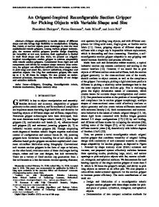
Fig. 4. FER of a polar SC decoder of blocklength N = 512 as simulated by our FPGA-based accelerator and calculated by a reference Matlab implementation.
VI.
C ONCLUSION
In this paper, we presented an FPGA-based accelerator for FER simulation of SC decoding of polar codes. By observing that the feedback part of the SC decoder can be ignored for the evaluation of the FER, the proposed accelerator is able to achieve a simulation throughput of 108 codewords per second. Moreover, we experimentally demonstrated the feasibility of using a large number of free-running XOR-based oscillators on an FPGA in order to generate the massive amounts of randomness required by our simulator. More specifically, for a maximum blocklength of N = 1024 and running at 100 MHz, our system generates more than 1 Terasamples of randomness per second. R EFERENCES [1]
[2]
[3]
[4]
[5]
[6]
B. Simulation results In Fig. 4 we present examples of FER simulation results for polar codes of various rates and blocklength N = 512. For each data point, frames were simulated until at least 10 frame errors were observed. The total simulation time was approximately 4 days. Moreover, the simulation results of our system agree well with values calculated with a Matlab script.
0.5
[7]
[8]
E. Arikan, “Channel polarization: A method for constructing capacityachieving codes for symmetric binary-input memoryless channels,” IEEE Trans. Inf. Theory, vol. 55, no. 7, pp. 3051–3073, 2009. M. Mondelli, S. Hamed Hassani, and R. Urbanke, “Unified scaling of polar codes: Error exponent, scaling exponent, moderate deviations, and error floors.” [Online]. Available: http://arxiv.org/abs/1501.02444 M. Bastani Parizi and E. Telatar, “On the correlation between polarized BECs,” in Proc. IEEE Int. Symp. Inf. Theory (ISIT), July 2013, pp. 784– 788. A. Mishra, A. J. Raymond, L. G. Amaru, G. Sarkis, C. Leroux, P. Meinerzhagen, A. Burg, and W. J. Gross, “A successive cancellation decoder ASIC for a 1024-bit polar code in 180nm CMOS,” in IEEE Asian Solid State Circ. Conf. (A-SSCC). IEEE, 2012, pp. 205–208. C. Leroux, I. Tal, A. Vardy, and W. J. Gross, “Hardware architectures for successive cancellation decoding of polar codes,” in IEEE Int. Conf. Acoustics, Speech and Sig. Proc. (ICASSP). IEEE, 2011, pp. 1665–1668. S. H. Hassani and R. Urbanke, “Polar codes: robustness of the successive cancellation decoder with respect to quantization,” in Proc. IEEE Int. Symp. Inf. Theory (ISIT), July 2012, pp. 1–6. C. Baetoniu, “Method and apparatus for true random number generation,” Jun. 17 2008, US Patent 7,389,316. [Online]. Available: http://www.google.com/patents/US7389316 Xilinx, “7 series FPGAs overview,” 2015. [Online]. Available: http://www.xilinx.com/support/documentation/data sheets/ds180 7Series Overview.pdf