An Intelligent Systems Approach for Detecting Delamination Defects due to Impact Damage in CFRP Panel by Using Ultrasonic Testing Anish Poudel1, Shanglei Li2, Tsuchin Philip Chu1, Donald Palmer3, and Roger Engelbart3 1 Department of Mechanical Engineering and Energy Process, Southern Illinois University 2 Department of Electrical and Computer Engineering, Southern Illinois University 1230 Lincoln Drive Carbondale, Illinois 62901 (618) 453-7049; fax (618) 453-7658 ; email
[email protected] 3
Boeing Research & Technology –St. Louis 5775 Campus Parkway, Bldg. 270A, Mail code S270-3800, Hazelwood, MO 63042 (314) 233-8321; fax (314) 234-6729; email
[email protected]
ABSTRACT Detection and classification of delamination defects during the manufacturing process and in-service operations are very important for ensuring the integrity, reliability, and safety of carbon fiber reinforced plastics (CFRP) panels. Pulse-echo ultrasonic testing is one of the powerful non-destructive evaluation (NDE) tools for identifying and characterizing these defects. However, conducting and interpreting ultrasonic test results fully depends on the knowledge and skills of the NDE operator. In addition, ultrasonic data are very difficult to interpret because they require the analysis of a continuous signal for each point in the material under consideration. This is tedious and may lead to misinterpretation of the data results if not perform correctly. An automated process is therefore required to manage large amount of ultrasonic signal data sets and extract important information from it. This research work applies an intelligent systems approach, specifically, fuzzy logic and artificial neural network (ANN) methodologies for the automatic detection and classification of delamination defects due to impact damage in CFRP panel.
INTRODUCTION Carbon fiber reinforced plastics (CFRP) are being extensively used in commercial modern aircraft applications due to its outstanding thermal and physical properties which include: high strength-to-weight ratio, low weight, high thermal shock resistance, a low coefficient of thermal expansion, maintenance of strength at high temperatures, a decrease in maintenance due to fatigue, greater crash safety etc. However, these composites are very susceptible to the damage mechanisms which become very difficult to identify at the early stage. In CFRP panels, the bond between the piles may weaken and propagate [1] or they may get damaged by low velocity impacts, for example, a tool dropped during maintenance, a bird or hail strike in flight or runway debris striking during takeoff or landing [2]. The presence of such delamination has greatly changed the physical properties of CFRP thereby reducing the stiffness of the structure. In addition, these damages sometime may not become visible from the impacted side but can spread within several piles under repeated loading eventually leading to brittle fracture. Therefore, there is an increasing need of identifying these damages at their early stages so as to prevent the catastrophic failure. To meet these challenges, various intelligent systems approach [1-6] is being applied to aid the inspection technique. For this work, we used an image approach to automatically detect the defect and quantify it. For this, first we inspected the CFRP panel with simulated delamination defects due to impact damage by using pulse-echo ultrasonic testing (UT) method at 5 MHz. After UT inspection, fuzzy clustering method and fuzzy logic rules based on the density and size of the defect were applied to the C-scan images. Then the artificial neural network (ANN) approach was used. For this, first several simulations were carried out to train and optimize the system by adjusting the structure and size of the network. After the training process an optimal network was chosen and it was presented with the new set of data to
Fuzzy Logic Fuzzy logic is a set of mathematical principles for representing knowledge based on the degrees of membership. This methodology was first was introduced by Dr. Lotfi Zadeh of U.C. Berkeley in the 1960's. Unlike two-valued Boolean logic, fuzzy logic is a multi-valued and deals with degrees of membership and degrees of truth, accepting
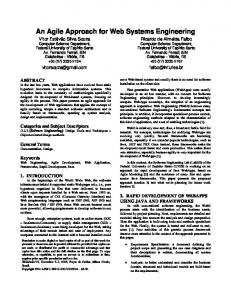
that things can be partly true and partly false at the same time [7]. A general fuzzy inference system (FIS) is shown in Figure 1. It consists of crisp input, fuzzifier, knowledge base, inference methods, deffuzifier, and a crisp output.
Figure 1: Fuzzy Inference System The FIS takes a crisp input and determines the degree to which they belong to each of the appropriate fuzzy sets via membership functions. A membership function is a curve that defines how each point in the input space is mapped to a membership value. The fuzzifier then measures the value of input variables and performs a scale mapping that transfers the range of values of input variables into the corresponding universe of discourse. The knowledge base consists of fuzzy sets and fuzzy rules. Fuzzy sets provide the necessary definitions which are used to define linguistic rules and fuzzy data manipulation and fuzzy rules characterizes the control goals and control policy of domain experts by means of a set of linguistic control rules. The inference method is the kernel of the FIS and it has the capability of making decisions based on fuzzy sets and fuzzy rules. Finally, defuzzifier performs a scale mapping that converts the range of values of output variables into the corresponding universe of discourse.
Artificial Neural Networks (ANN) An Artificial Neural Networks (ANN) is a mathematical model [8] that solves non-linear and complex problems and is inspired by the human nervous system. The ANN can be generally classified in two groups based on the connection patterns between their units and data propagation between them. These include feedback neural networks and feed-forward neural networks. Feedback neural networks have feedback connections i.e. data can flow from input to output units or vice versa like as in a human brain. Kohonen networks and Hopfield networks are examples of feedback neural networks. But, in feed-forward neural networks, data usually flow from input to output units in feedforward fashion. This is one of the simplest ANN where the information moves in only one direction from input to hidden (if present) to output nodes. Perceptron and Adaline are the classical examples of this kind of network.
Figure 2: A general two layer feed-forward neural networks
MLP have been successfully applied to solve various diverse and complex problems [8] by using a supervised learning process. MLP are generally characterized by the presence of an input layer, one or more hidden layers, and an output layer as shown in Figure 2. Each layer is connected to another layer by a series of weights known as synaptic weight. Changes in the synaptic weights change the behavior (state) of the neurons. The weights are usually adjusted during the training process. The learning algorithm that is commonly used within MLP is called error backpropagation. Error backpropagation algorithm basically consists of two passes within the network: a forward pass and a backward pass [8]. In the forward pass, an input vector is presented to the network and its effect propagates through the network layer by layer. Finally, a set of outputs is produced as the actual response of the network. This generates a difference (error) between the output of the network and the desired output. The synaptic weights of all networks are all fixed during the forward pass. Similarly, during the backward pass, an error signal is computed and it propagates backward through the network. Finally, the synaptic weights are all adjusted in accordance with an error-correction rule. The general training process for two layer feed-forward network as shown in Figure 2 shall execute following process: 1. Initialize the training input data and output data 2. Initialize weights to small random values, for example [-0.5 .. 0.5] 3. Initialize learning rate (η) and constant (λ) 4. While stopping condition is false do steps 5-10 5. For each training pair does steps 6-10 N i = 1,2,3,………N 6. Vk = f �∑M j=1 Wjk Vj �; Vj = f (∑i=1 Wij Vi ) 2 7. Error (ϵ) = ∑(Vk − ��� Vk ) j = 1,2,3,………M 8. ∆Wjk = −ηVj Vk (1 − Vk )(Vk − ��� Vk ) k = 1,2,3,………L N+M+L � 9. ∆Wij = −ηVi Vj �1 − Vj � ∑l=N+M+1 Vl (1 − Vl )(Vl − Vl )Wjl 10. Wij (new) = Wij (old) + ∆Wij ) ; Wjk (new) = Wjk (old) + ∆Wjk
EXPERIMENTAL PROCEDURE
Figure 3 (a) shows an image of the immersion ultrasonic system with associated instrumentation. A 5 MHz dual element Panametric transducer with a 2 inch focal length was utilized to inspect the CFRP panel. The scanning was conducted by placing the panel within the near-field of the transducer so as to prevent scattering and diffraction effects caused by beam spreading. The standoff distance between the transducer and the panel was set to be around 2 inches and the scan was conducted at an increment of 0.01 inches. The CFRP panel consisted of delamination defects due to impact damage at three different locations within the panel. These damages were artificially simulated by impacting the panel with an external object of known energy. The damages have been very hard to recognize just by visual inspection. The CFRP panel used measure 4 inch x 10 inch as shown in Figure 3 (b).
(a) (b) Figure 3: (a) Immersion ultrasonic system setup for CFRP panel (b) CFRP panel with delamination defect due to impact damage
Fuzzy Logic Implementation The C-scan image of the CFRP panel was first normalized into the gray level values (0 ~ 255) into a standard score of a pixel in order to satisfy the condition for fuzzy memberships. Two inputs (central pixel value and the mean of 3 x 3 window pixel values) and one output (defect level) variables were then modeled by fuzzy sets in their respective domains. Linguistic labels were also defined for membership functions based on the threshold values of the pixel. These threshold values were determined experimentally. Table 1 shows the linguistic labels and thresholds used for center pixel value, mean values of 3 x 3 window pixel, and output variable (defect level). Table 1: Linguistic labels and thresholds for (a) center pixel value (b) mean values of 3 x 3 window pixel (c) output variable (defect level) 0
40
70
100
Very Low (VL)
Low (L)
Neutral (N)
High (H)
110
255
Very High (VH)
(a) 0
90
120
150
160
255
Very Low (VL)
Low (L)
Neutral (N)
High (H)
Very High (VH)
230 Potential good area (L)
255 Positive good area (VL)
(b) 0 Positive defect (VH)
64 Potential defect (H)
200 May or may not be a defect (M) (c)
A 5 x 5 combination, i.e. 25 rules, was then created by comparing the central pixel value with a mean value of its 8 neighbors to generate the rule-base for the FIS as shown in Figure 4. These 25 rules were made by using if-then rules. For example, if a central pixel is VL and mean value of the 3x3 window pixel is a VL, the output (defect level) is VH meaning it is a positive defect area. Finally, each pixel defect level was determined based on these fuzzy rules.
Figure 4: Fuzzy logic rule-base for defect detection in CFRP panel
ANN Training The main objective of the ANN training process is to determine the synaptic weight values which will cause the output from the neural network to match the actual target value as closely as possible. Therefore, more effort was given to train the ANN with the appropriate data as much as possible. A two layer feed forward (one hidden layer)
ANN with the back propagation rule was implemented. During the training process, image feature of defect 1 (81 x 75 pixels) was used as input data and the fuzzy logic output result of the defect 1 was used as target data. The input and output data (images) that were used in the training process is shown in Figure 5.
(a)
(b)
Figure 5: (a) Density based raw image (b) Fuzzy logic output result The number of the hidden neurons that were used was 20 and it was determined during the experiment. The network training was repeated until a steady state was reached, where there was no any further change in the synaptic weights.
EXPERIMENTAL RESULTS The developed fuzzy rule was applied to the C-scan image from inspecting CFRP panel with delamination defects due to impact damage, using ultrasonic testing. Figure 6 (a) shows the image obtained from the UT inspection. In Figure 4 (b) the original image is normalized into gray level value. Figure 6 (c) is the final fuzzy logic output result that was obtained after applying the rules. The circled region in left side of the panel as shown in Figure 6 (c) is the marker that was attached to the panel for an indication purpose. From the results obtained, the fuzzy logic method is able to detect the defects with more confidence by eliminating the noises as seen in the C-scan image in Figure 6 (a).
(a)
(b)
Marker
(c) Figure 6: (a) C-scan image of CFRP panel (b) Density based raw image (c) Fuzzy logic output result
Similarly, the trained neural network was presented with new class of data that included a C-scan image of the CFRP panel with delamination defects due to impact damage. Based on the training, the network was able to detect the defect as shown in Figure 7. From this it is demonstrated that the system is able to learn the rules without knowing any algorithm. However, it is required that we need to train the system with numerous data and constantly update the knowledge so that the network can solve the problems efficiently.
Figure 7: ANN output result for the CFRP panel
CONCLUSIONS Analysis of the raw C-scan images of composites may not provide the reliable classification of different regions (defect, non-defect). Fuzzy logic and ANN methodologies were applied to classify the defect and non-defect areas in the CFRP panel with simulated delamination defects and the experimental results obtained for this panel have demonstrated the effectiveness of the proposed approach. However, an automatic classification of defects and nondefects areas in composites is fairly a challenging job which requires a considerable amount of research work to be carried out in future. The knowledge and the rules have to be constantly updated so that the systems get adapted with a new kind of problems in order to classify them. In addition, the performance of the system can also be increased by training the system with numerous and accurate data.
REFERENCES 1. 2. 3. 4.
5. 6. 7. 8.
Chakraborty D., “Artificial neural network based delamination prediction in laminated composites,” Materials & Design, Vol. 26 (1), pp. 1-7, 2005. Graham, D., P. Maas, G.B. Donaldson, and C. Carr, “Impact damage detection in carbon fiber composites using HTS SQUIDs and neural networks” NDT & E International, Vol. 37 (7), pp. 565-570, 2004. Pan, Y. C., T.P. Chu, and P. Filip “Intelligent Nondestructive Testing Expert System for Carbon-Carbon Composites Using Infrared Thermography,” Materials Evaluation, Vol. 69 (7), 2011. Poudel, A., and T.P. Chu, “An Intelligent Systems Approach for Detecting Defects in Commercial CarbonCarbon Composite Aircraft Brake Disk by using Air-Coupled Ultrasonic Testing,” Proc. of 20th Annual Research Symposium and Spring Conference, San Francisco, California, March 2011. Wei, Z. Z., Yam, L. H., and Cheng, L. L., “Delamination Assessment of Multilayer Composite Plates Using Model-based Neural Networks,” Journal of Vibration & Control, Vol. 11(5), pp. 607-625, 2005. Angelidis, N. N., & Irving, P. E., “Detection of impact damage in CFRP laminates by means of electrical potential techniques,” Composites Science & Technology, Vol. 67(3/4), pp. 594-604, 2007. Negnevitsky, M., Artificial intelligence: A Guide to Intelligent Systems, Addison-Wesley, Harlow, England, 2005. Haykin, S., Neural Networks – A Comprehensive Foundation, 2nd ed., Prentice Hall, 1999.