Sep 6, 1993 - Oriented System. 1 Introduction. In traditional programming environments, software de- velopment process is centered around a set of tools.
An Object-Centered Approach to Designing Programming Environments Yi-Jing Lin and Steven P. Reiss
Department of Computer Science Brown University Providence, Rhode Island 02912 CS-93-38
September 1993
An Object-Centered Approach to Designing Programming Environments Yi-Jing Lin and Steven P. Reiss Department of Computer Science Brown University, Box 1910 Providence, RI 02912 September 6, 1993
Abstract
1 Introduction
Traditional software development environments have been tool-centered. Artifacts of a software system are usually grouped according to the tools that handle them instead of logical units. This makes the development, maintenance and reuse of software di�cult. Besides, since the software development process is divided into smaller tasks according to the tools being used, this approach su�ers great performance deterioration when the software scales up, as each tool has to manage a larger amount of data. In this research we present an alternative approach to designing programming environments, in which software artifacts related to a software component are organized as an object, and then the software development process is centered around this kind of objects. With this approach, programmers will be able to organize a software system according to the logical relations between its components. Software reuse and cooperative programming will be more natural and the performance of the programming environment will not deteriorate as badly as in the traditional environments. In this paper, we describe the model of this new approach, and compare it with the traditional ones. We also present an programming environment called POEM, which is being developed at Brown University to verify our ideas. Compared with existing environments, the framework we present here is a paradigm shift from the procedural approach to the objectoriented approach. Key Words: Software Engineering Environment, Delegation, Version Framework, Distributed ObjectOriented System
In traditional programming environments, software development process is centered around a set of tools. Di�erent aspects of software engineering are carried out by di�erent tools, and di�erent tools usually have di�erent views of a software system. An editor sees a system as a set of les; a building tool sees it as a dependency graph with source data and derived objects; a manual browsers sees it as a collection of functionalities; and a visualization tool may see it as a set of interrelated software components. Most of these views do not re ect the logical structure of a software system, and the mappings between these views are complex but implicit. It is usually the programmer's responsibility to map di�erent views used by di�erent tools. Besides, in a large software system, software artifacts are usually organized according to the tools that manage them. Source programs are usually put into the same directory because they are managed by editors; binary les are put into another directory because they are all generated by compilers and used by link editors and loaders; document les are put into yet another directory because they are managed by document browsers. Under this kind of organization, directories and les are the major organizers, but they do not necessarily correspond to a clear-cut software component. Di�erent parts of an abstract software component, like its source, its binary code, and its documents, are scattered in several locations. This kind of organization makes the development and maintenance of software more di�cult. On one hand, related data and information are not brought together. Special e�ort should be paid to nd all parts 1
of a software component. This makes software reuse and cooperative programming more complex. On the other hand, vast amount of irrelevant information may distract programmers from solving the real problems at hand. Most users of an on-line manual system have experienced getting lost in manuals with too many irrelevant details, or wasting time reading information that is already known. It is also common to feel frustrated when trying to nd the de nition of a function in a large program. To solve these problems, we propose a new framework for building programming environments in an object-centered style. In this kind of environments, things are organized around individual software components instead of a set of tools. Each software components is represented as an object with a set of attributes. These attributes include data items, like its source code, object code, and documentation. They also include the operations that manages the software components, like editing source les, generating object les from source code, and fetching the associated manuals. The development of software is carried out by manipulating these objects. This approach has several advantages over traditional ones. First, by encapsulation, the internal complexity of a software component is hidden from its client. A cleaner and more standard interface of software components makes reuse easier. Potential reusers can access the documents without knowing their internal format, generate object code from source code without knowing the process of making, and incorporate them into new systems without knowing the locations of individual header les, object les, and manual pages. Second, by using links as attributes of these objects, the organization of software systems is more exible. Di�erent structures can be imposed on the same set of software components simultaneously. A software component can be reused by multiple projects, or shared by di�erent programmers working on the same project. We can also de ne di�erent kinds of links on the same kind of objects, so that programmers may have multiple logical views on the same program. Third, the performance of such an environment will not deteriorate like traditional ones do when the target software system scales up. Because the complexity of software modules are hidden behind simple interfaces, it will not add up as more modules are used in a software system. Each module sees only the submodules it directly uses. All the indirectly used modules are
hidden from it. In other words, programmers and tools can view a program at di�erent level of abstraction. At each level only the related information is presented. Fourth, this object-centered approach also makes the customization of a programming environment easier. Because the interface and the implementation are separated by encapsulation, di�erent tools with similar functionalities can replace one another without a�ecting other parts of the environment. Because inheritance allows incremental modi cation with backward compatibility, new environments can be built upon existing ones while ensuring that they can communicate with each other. This allows an environment to be tailored for di�erent people and di�erent working patterns. And last but not least, this approach makes program visualization easier, as the mapping between internal and graphical representations is inherently simpler in the object-oriented paradigm. It is easier to design a graphical interface that allows programmers to browse and manipulate a software system graphically. Although this framework works in a object-oriented style, it is not limited to object-oriented programming. It can be used for other programming paradigms as long as the software components in those paradigm can be represented as objects in the environment. For example, an object in the environment can be used to represent a function in the C language or a class in the C++ language.
2 An Overview of POEM To give readers some ideas about how a programming environment designed with our approach will look like, we begin our discussion by giving an overview of POEM. POEM (for Programmable Object-centered EnvironMent) is a programming environment currently under development at Brown University to verify our ideas. The design of POEM is based upon two observations. First, an e�ective software development is best accomplished by decomposing a software system into recursively contained modules. Second, software is more than the source programs. A complete software system also contains speci cations, source programs, binary code, documents, development history, statistical data, and so on. In POEM, all software artifacts that are directly related to an software component are organized into an 2
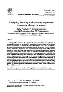
object called software unit. A software unit has an identity and contains a set of attributes. An attribute can be either a data member or an operation. Examples of operations are source code, header les, manuals, and object code; examples of operations are edit, compile, make, and read-manual. Programmers develop and utilize a software unit through its operations instead of directly accessing its data members. Figure 1 illustrates a simple software unit that represents a C function. It contains some links that point to les and other software units, and a set of simple data members that describe its properties. It also contains a set of operations that operate on its data members. A software unit may use other software units as its submodules. This relation is kept by the child links. With the child links, a large system can be organized as a set of interconnected software units. Figure 2 shows an example. The root software unit solve equations represents the whole system. All the other software units are its direct or indirect children. The source le associated with a software unit may be a logical le that maps to parts of a physical le. A physical le is partitioned into atomic spans, and then sets of spans form these logical les. Figure 3 shows the relation between logical les, spans, and physical les. A client of a software unit sees only the code that is directly related. In POEM, building a software system is carried out in a recursive fashion. The making of derived objects is carried out by the make operation associated with each software unit. When invoked, this operation sends a make message to each child of the software unit.After all the child software units nished their own make operations, the parent's make operation builds its derived objects from its local data and children's derived objects. Figure 4 illustrates this procedure. It is equivalent to a post-order traversal of a directed acyclic graph (DAG). Version control in POEM is also done in terms of software units. There can be multiple versions of the same software unit, and a versioned software unit can use other versioned software units as submodules. Figure 5 illustrates the versions in a software system. A software unit can reuse another existing software unit simply by creating a child link that points to it. By doing so, the whole submodule represented by the existing software unit is reused. This includes not only the source code and object code, but also the documents, the associated operations, and all the submodules, etc. If the reused software unit is versioned, the
gaussian.h header source
gaussian.c
object file manual
gaussian.o
child language=C
gaussian.m
author=yjl
To Software Unit TriangularFactorization
status=testing make();
To Software Unit BackwardSubstitution
edit_source(); read-manual(); Software Unit GaussianElimination
Figure 1: A software unit. Solve Equations
Input
Gaussian Elimination
Triangular Factorization
Row Exchange
Output
Backward Substitution
child link
Figure 2: A software system is represented as a set of software units linked together by the child links.
Gaussian Elimination
Triangular Factorization
Backward Substitution
double M[32][32]; ... gaussian() {...} backward_subt() {...} triangulization() {...}
double M[32][32]; ... backward_subt() {...}
double M[32][32]; ... gaussian() {... } backward_subt() {... } triangulization() { }
Physical File
double M[32][32]; ... triangulization() {...}
Spans Logical Files
Figure 3: A logical le associated with a software unit may map to parts of a source le. 3
reuser also gets all the versions. An example of reusing a software unit is shown in Figure 6. Developing a large system usually requires the cooperative work between multiple programmers. Using software units also helps in this case. Figure 7 shows an example in which two programmers are developing a software system cooperatively. In this example, each programmer is responsible for a major submodule, and uses a separate software unit to represent his view of the whole system. A programmer will usually choose to use the experimental version of his own submodule, and the older but more stable version of the other's submodule. By doing so, the workspace of each programmer is insulated from the frequent changes of the other ones. Figure 4: The making of a software unit is carried out In this example, a third software unit is created to by recursively sending the make message to its descenrepresent the workspace of the group. It uses the stadants. ble versions of both submodules and keeps the common data for the whole system. The "common data " may include the executable, the documents that describe the whole system, and the source code and object code of the main procedure that coordinates the operation of the submodules. Since the same kind of information is also required by the workspaces of individual programmers, the main software units used by both programmers are actually "shadows" that delegates to the main software unit of the group. Delegation lets a software unit to share others' data while allowing local modi cation. The mechanism of delegation will be discussed in more details in next section. Time
3 The Framework
Figure 5: Versions of a software system.
The framework of POEM is a three level structure, as illustrated in Figure 8. At bottom, the data layer is where the unstructured software artifacts are stored. In the middle, the object layer consists of virtual objects that reference items in the data layer and the object layer. At the top, the application layer contains interfaces to the external world. The data layer is basically the le system of the underlying operating system. Source code, object code, documents, and other data items are stored in les and directories. POEM also has mechanisms to support the use of logical les, which reference parts of a textual le. The virtual objects in the object layer are mainly software units. We call them virtual objects instead of simply objects because they usually do not directly
Polynomial Interpolation
Gaussian Elimination
Triangular Factorization
Substitution
Backward
Row Exchange
Figure 6: Reusing a submodule. 4
Workspace of programmer A
A
Workspace of the group
B
A
B
Delegation
Workspace of programmer B
A
B
Shadow
Figure 7: Cooperative programming using software units.
3.1 Virtual Objects and Classes
Application Layer
Software units are virtual objects. De nition of virtual objects in our framework is similar to that of object in most other object-oriented systems. Each of them has a unique identity and contains a set of attributes. An attribute may be either a data member or an operation. The internal state of a software unit is determined collectively by all of its data members, while its behavior by all the operations. Software units communicate with each other through messages. A message is accepted by an software unit if and only if it matches one of the software unit's operations. Virtual objects di�er from the \conventional" objects in that their data members may be links that reference data in the data layer, and their operations usually work directly on these referenced data. Because a referenced data item may be referenced by other virtual objects as well, it is not really hidden from outside accesses. Sharing of data between software units plays an important role in POEM. It is not only a way to save space, but also a method of communicating between software units. Software units belong to classes. A class is a template from which objects are created. All software units of the same class have the same set of attributes. To increase exibility, we provide users with the mechanism to de ne new classes instead of a xed set of prede ned classes. Di�erent classes of software units may be de ned to meet the need of di�erent programming languages and di�erent CASE tools. A programmer
Object Layer
Data Layer
process
Software Unit
file
logical file
Figure 8: The three-layer framework of POEM.
contain data. Instead, they organize the raw information and data within a programming environment, and present the organized information as encapsulated objects. The application layer contains user interfaces and interfaces to other systems. They are clients of the objects in the object layer. New interfaces can be added at any time. A user interface lets a programmer manipulate objects in POEM. An interface to other systems makes the data in POEM available to other programs. 5
may also customize software units to meet his special needs. De nition of classes can be reused through inheritance. Inheritance is not only a method to eliminate repetitive work, but also a mechanism to guarantee compatibility between di�erence classes. Classes derived from the same ancestor class are ensured to contain the operations de ned by their common ancestor. This guarantees the compatibility between customized software units. An software artifact referenced by a link of an object can be either a source data item or a derived data item. Source data items contain the essential information of an object. Deletion of an source data item leads to loss of information. Derived data items are derived from other source data items referenced by the same object. Deletion of a derived data item can be recovered by processing the source data items; it does not involve information loss. Derived data items can sometimes be considered as the performance optimizers.
unit. According to this de nition, each software unit uniquely decides a module, and each module consists of a connected DAG of software units. The software unit that decides a module is called the module's root software unit. Software units that are directly referenced by the root software unit correspond to the module's direct submodules. In procedural languages, this relation usually coincides with the calling relations between procedures, but they are not always the same. for example, a procedure that calls itself is not considered as a submodule of itself; two procedures that call each other are considered as sibling submodules instead of a parent-child pair. Therefore, if we want to keep the calling relations in a software system, we should represent it as a separate attribute of each software unit. In object-oriented languages, parent-child relations usually run in parallel with the part-of relations and inheritance relations. A class used as a part of a new class de nition is considered as a submodule. A parent class in the inheritance hierarchy, interestingly, will usually be considered as a child. Other than software units representing submodules, a software unit usually directly reference a set of software artifacts in the data layer. These artifacts may be source and object code of the main routine, or documents that describe the whole module. We call these artifacts the local data of a software unit. Operations of a software unit usually form pairs, one of which applies to its local data and the other applies to the whole module. for example, the compile operation builds the local derived objects; the make operation builds derived objects of the whole module. A local copy copies a software unit along with its local data; a module copy copies all software artifacts of a module. Operations that operate on the whole module can be de ned in a recursive style. Messages requesting the same operation are sent to all the child software units. To build the derived objects of a certain module, the root software unit usually needs the local data of its child software units, which include header les, object les and libraries. The root software unit can get the location of these objects by sending query messages to its child software units. Sometimes, a submodule also needs the local data of its parent module. For example, constants and global variables of a module may be de ned in a header le which is shared by all its submodules. A submodule can similarly get the location of these shared objects by sending query messages to
3.2 Relation between Software Units
Software units may reference one another through links. Di�erent kinds of links can be de ned to represent di�erent relations between software components. For example, a software unit representing a class may contain a link that represents the inheritance relation, and other ones that represent the part-of relations. If multiple links are de ned in software units of a program, multiple views are available for programmers. Empirical study shows that multiple-view software development may promote productivity signi cantly [1]. Among the possible links that can be de ned, child link, as described in the previous section, plays a special role in our framework. It de nes the structure used by system building and version control, and corresponds to the module-submodule relation in software decomposition. As there is no de nite way to decompose a software system[2], there is no de nite way to de ne the child links. We only impose the restriction that the child links should not form cycles, and the structure formed by the child links should re ect the process of building a software system. Since the child links cannot form cycles, all the software units and their child links together form a directed acyclic graph (DAG). In our framework, a module is de ned as the set of all software units that are reachable through child links from a certain software 6
its parent. Modules that do not need data from their parents are called autonomous modules. An autonomous module is ready for reuse. It is not necessary to rebuild its derived objects when it has a new parent. On the other hand, a non-autonomous module uses data of its parent. It needs an explicit link pointing to its parent so that it knows where to get the necessary information. Its derived objects have to be rebuilt when the module is reused.
Class A inherits from
inherits from
Class B
Class C Class Level
instance of
instance of
Object Level
instance of Object X
instance of
Object Z delegates to
Object Y
Object Z delegates to
3.3 Delegation
Figure 9: The hybrid model with both inheritance and If we directly reuse a non-autonomous software unit, its delegation. contents usually become invalid for the original system, as its derived objects will be rebuilt and its parent link must be modi ed. If we copy the whole software unit delegation. Thirdly, a delegation system will be slower before reusing, extra space will be needed, and updates than an inheritance system, because the stored values on the original software unit will not be known to the of attributes should be found at run-time, and there reuser even when it is desired. Ideally, we should create might be multiple levels of indirections (delegations) a shadow software unit that shares most data with the between an object and the stored values. original software unit but has its own copy of parent In contrast, the class-inheritance model gives users link and derived objects. This kind of shadow software more manageability at the expense of exibility. It disunits are also very useful in a cooperative programming cerns the roles of classes and those of objects. Classes environment. As shown in the example of Figure 7, separate structure and behavior concerns from that of a programmer usually needs to \reuse" the modules run-time computation. All objects of the same class developed by other members of a programming team. are guaranteed to have the same behavior pattern. To capture the behavior of these shadow objects, the However, even with the class variables supported by delegation model [3] [4] [5] is a natural candidate. The some inheritance systems, the sharing of data at obdelegation mechanism is proposed as an alternative to ject level is quite limited. Without using class varithe mechanism of classes and inheritance. An instance ables, sharing of data between two objects has to be may share data and behavior with the prototype it del- implemented by creating a separate object that stores the common values; using class variables, all objects of egates to while having its own local modi cations. Delegation gives us great exibility. It enables in- the same class have to share a single value. The incremental modi cations at the object level, allows de- heritance model does not support asymmetric sharing pendencies between objects, and decreases the stored either. information by sharing. However, it usually results Since neither the delegation model nor the inheriin a chaotic and ine�cient environment. Firstly, be- tance model will ful ll our requirements, our solution cause instances can rede ne the attributes of the pro- to this predicament is to use a hybrid model. We imtotypes, there is no guarantee of \upward compatibil- pose the restriction that delegation only be applied to ity." That is, what is true of the prototypes might the instance variables, but not to the operations. That not be true of the instances. Secondly, the seman- is, an object can delegate the values of its instance varitic complexity of the system will increase greatly. Be- ables to another object and thus share the variable, but cause all objects can serve as prototypes, and the pro- it cannot delegate its operations to another object to totypes have no knowledge about the existence of their share the behavior. Furthermore, all the operations instances, modi cations of any existing objects might should be de ned on classes. Objects are not allowed cause some unpredictable changes of behavior of other to de ne their own operations. Figure 9 illustrates objects. Knowing where the value of a certain attribute the relation between objects and classes in this hybrid is stored becomes important, but it is hard because the model. value might be embedded deeply in arbitrary levels of Under this model, the incremental modi cation and 7
sharing of values are done at the object level, while the incremental modi cation and sharing of behavior are done at the class level. While the values can be managed exibly, the behavior of objects are still predictable because operations are stored in the classes, which are de ned at the design time and are not subject to frequent changes. Besides, all the objects of a class have the same behavior pattern.
their child links form a DAG rooted at a single software unit. Consequently, our version control framework is de ned in terms of this DAG structure. Our version control framework begins with the versioning of atomic objects in the data layer. An atomic object is a software artifact that does not contain or reference any other versioned object. It cannot overlap with other atomic objects, either. Object les are examples of atomic objects. For a source program or document, if no logical le is mapped into it, the whole le is considered an atomic object. Otherwise, the spans de ned by the logical les are atomic objects. The versioning of atomic objects is straightforward. A xed version is a semantically meaningful snapshot of an object. Applying a checkout operation on a xed version generates a new active version. The new active version is said to be derived from the xed version. It correspond to the present time and is mutable. Applying a checkin operation on an active version turns it into a immutable xed version. Multiple checkout operations can be applied on the same xed version to create branches. Two xed objects on different branches can be merged to create a new active version. In short, all version instances of an atomic object with their is-derived-from relations form a DAG, in which all internal nodes are xed versions and leaf nodes can be either xed versions or active versions. We also de ne the is-a-descendant-of relation as the re exive and transitive closure of is-derived-from. Formally,
3.4 Logical Files
One of the major goals of our framework is to let programmers work directly with logical units. When examining the source code of a software unit, what the programmers see should be the source code of the software unit, and nothing else. One way to achieve this goal is to store each logical unit in a separate le. For example, if a program consists of several procedures, we can store each procedure in a separate le. This approach is simple and straightforward, but it has some disadvantages. Finer granularity usually causes overhead in system building, and it fails for programming languages with nested scoping. In a language like Pascal, because logical units may include one another, it is impossible to store each logical unit in a separate le. Therefore, we still keep several logical units in a single le, but use a logical le system to create the illusion of les with single software unit. The logical le system is a mapping mechanism built on top of current le systems. It logically divides a physical le into several mutual exclusive spans, and then maps each logical le to a set of spans. When reading from the physical le, it lters out the irrelevant information; when editing the content of logical les, it maps the modi cation back to spans in the physical le. The disadvantage of this approach is that we need a specially designed editor to manipulate these logical les. This editor should use services from the logical le system instead of the underlying physical le system. It should also help mapping from logical les to spans.
De nition 3.1 For an atomic object, an version X is a descendant of another version Y if and only if 1. X equals to Y , or 2. X is derived from Y , or 3. X is derived from Z , and Z is a descendant of Y Atomic objects are referenced by software units either directly or indirectly through logical les. In terms of version control, logical les can be thought of a special case of software units. They reference atomic objects and are referenced by other software units. Therefore, all the following discussions and definitions about software units also apply to logical les. A version of a whole module can be represented by a version of its root software unit. In this framework, links between objects are represented as (object name, version ID) pairs. Each of these pairs uniquely decides a version instance. Then, since a software unit
3.5 Version Control
Since our framework is aimed to support a logical organization of software systems, it is necessary that our version control framework is de ned in terms of software components instead of les and directories. As stated in section 3.2, software units of a module and 8
uniquely decides a module, a version of a software unit also uniquely decides a version of the module it represents. Properties and operations of a versioned software unit are de ned in terms of the objects it references. De nition 3.2 A version of a software unit is a xed version if and only if 1. the contents of its data members, which include links, are immutable. 2. all the local data and software units it references are of xed versions. Otherwise, it is an active version. Again, a xed version of a software unit represents an immutable snapshot of the whole module; an active version represents the present time and is subject to changes. A checkout operation can only be applied to xed versions. A checkin operation can be applied to both active versions and xed versions, but it has no e�ect in the latter case. De nition 3.3 Applying a checkin operation on a software unit is equivalent to: 1. applying checkin operations to all the local data and software units it references, and 2. make its data members immutable. De nition 3.4 Applying a checkout operation on a software unit is equivalent to: 1. applying the checkout operation to all the local data and software units it references, and 2. creating a copy of the software unit and make all its links point to the versions newly created in step 1. De nition 3.5 For two versions X and Y of a software unit U, X is a descendant of of Y if and only if 1. For each local data item P referenced by Y, the corresponding object P' referenced by X is a descendant of P. 2. For each child software unit S of Y, there is a corresponding software unit S' which is a child of X and is a descendant of S. This de nition implies that if X is a descendant of Y , the DAG of the software artifacts rooted at X is isomorphic to the one that rooted at Y , and each node in the X 's DAG is a descendant of the corresponding node in Y 's DAG. This version framework is similar to that of PCTE+[6]. But while PCTE+ uses stable links to control the updates of objects, xed version and active
version are properties directly associated with objects in our framework.
4 Comparison Object-oriented paradigm has attracted much interest because it achieves data abstraction, scalability, and code reuse in a natural way. It also makes coarse-grain concurrency easier. Although our framework somewhat deviates from the \standard" object-oriented paradigm, most of these properties are retained. In this section, we examine how these principles can be applied to the design of a programming environment, and compare this object-centered approach with the traditional approaches.
4.1 Structures of Software Systems
Software units are the information organizers in our framework. A software unit corresponds to an abstraction, and it brings together all the related software artifacts. Because software development is carried out in terms of these units, programmers are directly dealing with logical units like functions, classes, and modules. In contrast, in traditional environments programmers have to deal with physical entities like tools, les, directories, and line numbers. The necessity of dealing with these things only distracts programmers from solving the real problems. Attributes of a software unit provide di�erent views of an abstraction. For examples, documentation gives the informal description, header les correspond to a formal speci cation, source code is the implementation, and object code is in a directly usable form. Properties like the development status, the underlying programming language, target machine architecture, and keywords can also be de ned as simple attributes. All the information helps a programmer to understand a software unit. Our approach also helps to get rid of irrelevant information. By using logical les, programmers can work on an individual function or class without being bothered by other code that happens to reside in the same source le. By encapsulating submodules into autonomous software units, their implementation is hidden from the development consideration at a higher level. The lack of associations between related software artifacts in traditional environments has long been rec9
ognized. A popular approach to solving this problem is to use a hypertext system [7] [8]. A hypertext system has the exibility to establish links between any two arbitrary software artifacts. However, too many unrestricted links in a software development environment is just like too many goto statements in a program, they bring the navigation problems and cognitive overhead. Compared with this hypertext approach, our approach organizes software in a more hierarchical way. A software system is rst decomposed into software units, and then into individual software artifacts. All the links leading to individual software artifacts originate from the software units instead of other software artifacts.
That is the reason why some such environments work very well for small and medium size projects, but not so well for larger ones. In our framework, not the whole system is necessary to be loaded in at once. If we are working on a module, only its corresponding software unit and those of its submodules are essential. The loading of other software units can be done in a lazy-evaluation style. If searching of information is required, the DAG of software units that represents a module gives a natural boundary of search space.
4.2 Scalability
The demand for concurrency in a programming environment comes from two sources. For individual programmers, concurrency is desired because it speeds up the execution of tasks. For cooperative programming, concurrency is required to allow multiple programmers to work simultaneously. Software development involves a lot coarse but rather independent tasks. Editing, compiling, and linking all have relatively long life span. These coarse grain tasks are ideal for parallel execution as there is not much communication between them. Each task can be bound to a process and executed concurrently as long as they do not access the same data items. Object-oriented paradigm makes concurrency easier. The autonomy of objects makes them a natural unit for concurrent execution. Since data members are local to an object, each object can execute its operations independently. By replacing synchronous messages with asynchronous messages, an object-oriented system can be parallelized without much modi cation. Concurrent execution in our framework is further simpli ed as a software unit cannot directly contain other software units. If we impose the restriction that only one thread of control be allowed in a software unit, operations on the same data can be e�ectively serialized. However, some extra mechanism and restriction are required as the result of our deviation from the standard object-oriented model. Because software artifacts referenced by links are not directly contained in software units, they are not really hidden from outside accesses. To guarantee correct concurrent executions, we should either restrict the sharing of these data or use some locking mechanisms.
The key to manage complexity is divide-and-conquer, that is, dividing a large task into smaller ones and encapsulating the internal complexity of these smaller tasks with simple interfaces. This is important not only for programmers, but also for the performance of a programming environment. It reduces the amount of data to be managed at the same time. In traditional environments, the software development process is divided into smaller ones according to the tools used. Editors, compilers, build systems, version control systems, and CASE tools all carry out a portion of the development process. As a software system becomes larger, the number of subtasks, which is equivalent to the number of tools used, does not increase. Each tool thus has to manage a larger amount of data with a more complex structure. This causes performance deterioration. In contrast, in our framework the software development process is divided into the development of individual software units. As a software system becomes larger, there will be more software units but each software unit does not become larger. A software unit sees only its parent software unit and the child software units it directly uses. The internal complexity of submodules is hidden behind the abstract operations of software units. Some advanced programming environments use a large centralized database to keep information and data of software systems being developed [9] [10] [11]. These environments usually support more and better functionalities than traditional ones. But as the target software system becomes larger, the database also becomes larger. This simply leads to more overhead.
4.3 Concurrency
10
4.4 Graphical User Interface
cel by some rather subtle advantages. Amber [17] augments a subset of C++ with primitives to manage concurrency and distribution. PCTE and PCTE+ supply a public tool interface to support the construction of software engineering environments. These works address several issues that are important in the implementation of POEM.
Graphical interfaces enable users to grasp the big picture of a complex system quickly. During the development of a software system, it helps to understand the structure of software and the relationship between concepts. Designing a graphical user interface for an objectoriented system is easier than for a procedural system. The mapping between internal representations and graphs is basically one-to-one. A software unit can be represented as a node in a graph. Its attributes, such as type, language and owner, can be represented as graphical attributes of the node, such as color, shape, and size. The relations between software units can be represented as edges between the nodes. Operations of a software unit can be represented as the items in the associated pull-down menu. Because this mapping is one-to-one, using a graphical user interface to edit the structure of a module is as straightforward as to browse it. A programmer can graphically build the skeleton of a module by creating a DAG of software units. Flesh of this skeleton can be lled in later by invoking operations associated with each software unit.
4.5 Other Related Work
5 Conclusion We have presented the basic ideas of an object-centered approach to designing programming environments. We illustrated how an object-centered programming environment should look like, discussed its models, and compared it with the traditional environments. We also presented some of the potential challenges to this kind of programming environments. Compared with the traditional tool-centered approach, our object-centered approach is just in its infancy. There is still a long way to go before it can attain the same level of maturity as the traditional ones have. But with the inherent advantages as discussed in this paper, we believe that the object-centered approach is very promising, and it will become a major player in the world of software engineering.
Field [12] and SoftBench [13] allow a programmer to browse an existing software system in terms of logical units. Users can also visualize the interaction between abstractions at run time. But in these systems, software is organized in the traditional way instead of around these logical units. The mapping between logical units and programs is achieved through special mechanisms. Versioning of composite objects is not common in existing programming environments, but has been well discussed in the design of computer-aided design databases. Katz gave a good overview of these researches in [14]. In these systems, components of a composite object are associated by individual links instead of links from a single object. This leads to a more complex version control framework. There are also languages and systems aimed to supply a generic environment for the development of distributed object-oriented systems. Emerald [15] is a strongly typed object-oriented language that supports location-independent invocation and object migration. DOWL [16] supplies similar features but claims to ex11
References [1]
[2] [3] [4] [5] [6]
[7]
[8] [9] [10] [11]
[12] Steven P. Reiss, \Connecting Tools Using Message Passing in the Field Environment," IEEE Software 7(July 1990), 57{66. Scott Meyers and Steven P. Reiss, \An Empiri- [13] M.R. Cagan, \The HP SoftBench Environment: cal Study of Multiple-View Software Develpment," An Architecture for a New Generation of Software Proceedings of the Fifth ACM SIGSOFT SymTools.," Hewlett-Packerd Journal (June, 1990). posium on Software Develpment Environments 17 [14] Randy H. Katz, \Toward a Uni ed Framework for (December 1992), 41{46. Version Modeling in Engineering Databases," ACM Ian Sommerville, Software Engineering, 3rd ed., Computing Surveys 22(December 1990), 375{408. Addison Wesley, Wokingham, England, 1989. Black, Norman Hutchinson, Eric Jul, Henry Lieberman, \Using Prototypical Objects to [15] Andrew Henry Levy, and Larry Carter, \Distribution and Implement Shared Behavior in Object Oriented Abstract Types in Emerald," IEEE Transactions Languages," ACM OOPSLA'86 (Sep. 1986). on Software Engineering SE-13 (Jan. 1987). David Ungar and Randall B.Smith, \Self: The [16] Bruno Achauer, \The DOWL Distributed ObjectPower of Simplicity," ACM OOPSLA'87 (Oct. Oriented Language," Communication of the ACM 1987). 36(September 1993), 48{55. Lynn Andrea Stein, Henry Lieberman, and David [17] J. Chase, F. Amador, E. Lazowska, H. Levy, and R. Ungar, \A Shared View of Sharing: The Treaty Little eld, \The Amber system: Parallel programof Orlando," In Concepts, Applications and ming on a network of multiprocessors.," ProceedDatabases, Reading, Massachusetts (1989). ings of the Twelfth ACM Symposium on Operating Gerard Boudier, Ferdinando Gallo, Regis Minot, System Principles, New York(1989). and Ian Thomas, \An Overview of PCTE and PCTE+," Proceedings of the ACM Software Development Environments, ACM SIGSOFT Software Engineering Notes 13 (Nov. 1988), 248{257. James C. Ferrans, David W. Hurst, Michael A. Sennett, Burton M. Covnot, Wenguang Ji, Peter Kajka, and Wei Ouyang, \HyperWeb: A Framework for Hypermedia-Based Environments," ACM SIGSOFT '92: Fifth Symposium on Software Develpment Environments (SDES), New York, NY (December 1992). P. Brown, \Integrated Hypertext and Program Understanding Tools.," IBM System Journal 30 (1991), 363{392. Alan W. Brown, \Integrated Project Support Environments: The Aspect Project," The APIC Series, London, England(1991). Yih-Farn Chen, Michael Y. Nishimoto, and C. V. Ramaoorthy, \The C Information Abstraction System," IEEE Transaction on Software Engineering 16(March 1990), 325{334. Premkumar Devanbu, Ronald J. Brachman, Peter G. Selfridge, and Bruce W. Ballard, \LaSSIE: A Knowledge-Based Software Information System," Communication of the ACM 34(May 1991), 34{49. 12