In these experiments, a GSM network application has been simulated on top of ... rate has been constant for data services, but the situation will change in the ...
Application of Distributed Workstation Environment to the Parallel Simulation of Mobile Networks Veikko Hara1, Jarmo Harju2, Jouni Ikonen3 and Jari Porras3 1
Technical Research Center of Finland, P.O. Box 1202, FIN-02044 VTT, Finland 2 Tampere University of Technology P.O. Box 553, FIN-33101 Tampere, Finland 3 Lappeenranta University of Technology P.O. Box 20, FIN-53851 Lappeenranta, Finland
Abstract In this paper, a distributed workstation environment, Diworse, for parallel simulation is presented. Distribution of the simulation model in Diworse is based on the modification of the conservative Chandy-Misra algorithm with null message delivery and constant lookahead. Simulation experiments have been carried out in the Ethernet network with TCP/IP protocols. In these experiments, a GSM network application has been simulated on top of Diworse. Results obtained from the simulations are compared to the results achieved from the sequential simulation environment. The results indicate that Diworse is suitable for simulation applications that need a lot of computational power.
1. Introduction The number of users in digital or second generation mobile networks increases rapidly. Digital networks contain numerous advanced features compared with analogue cellular mobile networks. Consequently, the operation of the radio interface in second generation systems is complex, and is controlled by a considerably large set of parameters. So far the transmission rate has been constant for data services, but the situation will change in the next few years. Namely, for example in the GSM (Global System for Mobile communication), the new variable speed packet and circuit switched data services create new demands to the operators. Systems become more and more complex to operate, and network simulation gives appropriate tools to analyze and to optimize the cellular radio networks. Even though network planning in second generation systems is complex, it will become even much more difficult at the beginning of the next century when broadband mobile networks will be launched into operation. In the next five years, the third generation mobile networks, called the UMTS (Universal Mobile Telecommunications System), will be developed. This new generation is based on application and service oriented technology that supports on-demand transmission capacity up to 2 Mbps in various radio environments. The ultimate goal is to provide seamless end-to-end services to the users by using a combination of fixed and wireless/mobile access technologies. This
development has two important consequences. Firstly, the radio access networks in densely populated areas will be broadband microcell networks, which require broadband fiber connection to the backbone networks. How the intelligence, including the mobility management in these networks is distributed, is an open question. The traffic modeling must be developed based on the definition of the mobility management. Secondly, sparsely populated areas will be covered with overlay cells having less bandwidth than the broadband microcells. This implies that the future cellular architecture will be based on inhomogeneous cellular networks, where narrowband umbrella cells cover areas outside microcells. Simulation is applied as a network planning tool in studying systems that are analytically insolvable or in which real experiments are time consuming or expensive. The diversity of the parameters, controlling the operation of this network, restricts the possibility of an analytic approach. Network planning tools typically consist of four separate parts, which are the radio wave propagation model, traffic generator, system simulator and the network optimization algorithm [Har92]. The first one defines base station locations, carriers and coverage areas. The traffic generator models the roaming of the mobile stations. The system simulator uses the propagation model and traffic generator for defining the network behavior. Optimization tools like the neural network approach is used to teach the network either from real data or from simulation to operate more efficiently. The inhomogeneous mobile networks and increasing need of computation time require the development of new modeling and simulation methods. A promising modeling and simulation approach seems to emerge from parallel simulation. Parallelization of the simulation can be achieved by using either an expensive multiprocessor machine or by using several single processor machines connected through a network. Multiprocessor machines are able to take advantage of the shared memory, which simplifies the implementation and improves the performance of the simulation. However, the achievable gain in the performance is usually small as the number of processors available is limited. Distributed environment offers an alternative possibility as the number of parallel computing units, e.g. workstations, is theoretically unlimited. The computational power of this environment can be enormous, although taking advantage of it is much more complicated than in a multiprocessor environment with the available shared memory. The lack of shared memory in a distributed environment requires that a message passing mechanism between logical processes must be implemented. The use of a message passing environment sets requirements and limitations for the parallel algorithm used in the simulation. Several general purpose parallel simulation methods have been developed for various parallel architectures. These methods can broadly be divided into two classes, conservative and optimistic, depending on the algorithm to preserve the correct order of events. In conservative methods, such as Chandy-Misra algorithm [Cha79], strict synchronization is used to prevent the incorrect simulation order. Conservative methods are usually simple to implement, but due to strict synchronization they may not fully utilize the parallel potential of the simulation application. Optimistic methods, such as Time-Warp [Jef85], allow events to be simulated with less synchronization, but out of order events must be detected and results corrected. The incorrect simulation order and operations caused by it introduce an additional overhead for the optimistic methods.
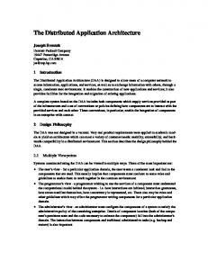
2. Diworse Diworse is a distributed workstation environment for implementing large and time consuming simulation applications. By using parallel discrete event simulation, the time needed for the applications can be significantly reduced. The object oriented implementation of the environment allows fast and easy changes to the simulation application as well as to the underlying structures. Distribution of the simulation application is based on a modification of the conservative Chandy-Misra algorithm, SimL∞p [Por96]. SimL∞p reduces the number of null messages and improves the execution of messages by allowing simulation of several messages in each simulation round. Null message cancellation further improves the performance. 2.1 Logical system concept The SimL∞p algorithm uses a logical system concept presented for the parallel simulation [Cha79]. The logical system concept is based on the distribution of the simulation into two or more independent parts, i.e. logical processes (LP), which can be executed on different processors. Simulation of events occurs in logical processes independently, but events may affect other logical processes and therefore logical processes must be connected via logical channels. All the communication between logical processes is performed by interchanging timestamped events through these channels. Input and output queues can be attached to incoming and outgoing channels. The following Figure 1 presents a connection graph for four logical processes. Logical processes are connected through directed channels, and connections are created according to the purpose of each logical process. Local loop channels are used for delayed actions in a given logical process. LP1
LP4
LP2
LP3
Figure 1. Connection graph for LPs of a parallel system.
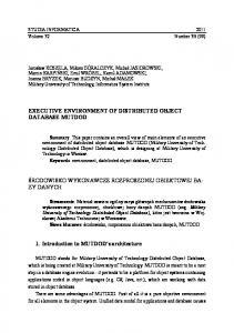
2.2 Structure of Diworse The basic structure of the implemented simulation environment is presented in Figure 2. The elements of this structure can be divided into three distinct layers, i.e. implementation of the simulation services, interface to these services and the simulation application. Implementation of the simulation services contains functions for the SimL∞p algorithm and message transmission. The distribution environment can be easily changed by implementing or selecting appropriate message transmission functions. Interface to the services contains specifications,
i.e. base classes, for elements used in the distribution. Simulation application level implements the logic of the simulation i.e. it decides when to create new messages and what to do with the received messages. New applications can be easily implemented on top of the interface by inheriting the properties of the base classes to the application specific elements.
Simulation application Message managers: Simulation based on the contents of the received message and state variables Creation of new messages
Services interface Specifications of: Logical processes & state variables Message contents Channels & buffers
Implementation of services Allocation & deallocation of messages SimLoop algorithm & null messages Functions for message transmission
Distributed
Shared
Sequential
Figure 2. Layer structure of Diworse.
The structure of Diworse allows the implementation of different simulation applications on top of the service interface. Applications use specifications given by the interface layer and implement only the functions for message managers. Simulation of a message executes exactly those functions which are specified for it in this layer. The services interface layer consists of specifications for the simulation environment. The main parts of the logical system, i.e. logical processes, logical channels and messages are specified in an object-oriented manner, which allows an inheritance from these main components. The base logical process class contains basic queue and message structures as described in logical system concept.
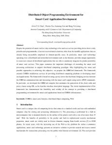
Implementation of the SimL∞p algorithm can be built to satisfy different distribution concepts, i.e. sequential, shared memory and distributed memory. Sequential approach shares the same logical process structure as the distributed and shared memory environments, but all messages are simulated using only one logical process and its message structure. Shared memory environment differs from the distributed environment only at the message transmission functions. While shared memory environment moves messages from one memory place to another, the distributed environment sends the message over the network. Distributed environment can be easily implemented to support several network concepts, e.g. Ethernet and ATM. 2.3 Components of Diworse The Diworse is based on the object oriented approach. All components of the environment are implemented as classes that allow an easy adaptability of the environment and the application for different purposes. The main components of the distribution are based on the logical system concept. These components are presented in Figure 3. process Scheduler LP LP
LP
Figure 3. Main components of the Diworse.
In the following, the main classes and their properties are introduced: • Scheduler Scheduler serves as the communication element of the simulation. In each workstation, which participates in the simulation, a single scheduler is needed. Scheduler sends and receives messages and transmits them to appropriate logical processes according to the sender and receiver information included into the message. Scheduler also controls the execution of logical processes using round robin method, i.e. logical processes are executed sequentially inside a workstation. • Logical process Logical processes are the main elements in the distributed simulation. They represent both the simulation application and the distribution. The SimL∞p algorithm is implemented inside the base logical process class whereas the application dependent properties are located in the user defined logical processes. Logical processes use logical channels to transfer messages in the simulation.
• Queue Queue classes implement the logical channels of the distributed simulation model. Different structures, e.g. binary tree and linked list, can be defined for different channels. Queues are used for the communication by logical processes. Incoming events are placed into the queue by the scheduler, and they are consumed by the logical process. For outgoing messages the procedure is opposite. Null message cancellation can be easily implemented in the queue class. • Sockets Sockets are used for implementing the communication interface between distributed elements, i.e. different physical processes. Socket classes for different communication environments can be implemented. In the Ethernet network, both TCP and UDP protocols can be used. Sockets take care of start and end of the communication as well as the transfer of messages between communicating processes.
3. Operation of Diworse When the simulation application dependent elements have been implemented and compiled the application can be run on top of Diworse. The configuration of the simulation environment can be set dynamically, and the progress of simulation can be monitored. Dynamic configuration can also be used for the application. The configuration, operation and monitoring properties of Diworse are described in the following subsections. 3.1 Configuration of the simulation system [GLOBAL] // Number of sections are given here NumSections = 5; // Schedulers SchedLst = { "Sched1", "Sched2", };
"max.it.lut.fi", 6031, "dior.it.lut.fi", 6032
[Manager] // Manager host and port MHost = "gandalf.it.lut.fi"; MPort = 6029; [BSS1] Sched = 1; NeighLst = {2}; BrdcstPeer = 2; [MS1] Sched = 2; [BSS2] Sched = 2; NeighLst = {1}; BrdcstPeer = 1; [MS2] Sched = 1; Example 1. Configuration file for setting physical locations of the LPs.
The physical location of simulation processes can be controlled with a configuration file. An example of a configuration file can be seen in Example 1. Configuration file defines where simulation processes are located, i.e. physical distribution, and how logical processes are connected to each other, i.e. logical channels. Other configuration files can be used for setting up a simulation application. For example in GSM mobile network simulation, these files include information about locations of base stations, communication frequencies, transmission powers, etc. 3.2 Execution of the application in Diworse Manager
LP Scheduler
LP
LP
Scheduler
Scheduler
Scheduler
Agent
Agent
LP
LP
Agent
Figure 4. Execution of LPs in Diworse.
Diworse is physically based on a Manager-Agent concept. Agent processes contain the logical processes of the simulation model, and they take care of the distributed simulation. The Manager process is used for controlling the start and the end of the simulation as well as error situations. It does not have any effect on the simulation, but it merely synchronizes logical processes in the beginning of the simulation. All the Agent processes are executed in separate workstations whereas the Manager process can be executed in a separate workstation or in the same workstation as one of the Agents. Therefore Manager process and Agent processes form the base for the physical communication of the logical simulation model, since the physical communication happens between separate workstations. In Ethernet, the inter workstation communication has been implemented by using TCP and UDP protocols. TCP slows down the simulation, but it was found to be more suitable for distribution because of its reliability. 3.3 Simulation procedure Simulation is started by a launch program. It sends simulation processes to the workstations defined in a configuration file. Processes establish connections between each other, and when all processes are ready Manager starts the simulation. During the simulation, Manager does not actively participate into simulation. However, the user can use it to monitor or stop the simulation. In the end of the simulation, Manager collects simulation results from different workstations. In case of a critical error, Manager automatically terminates the simulation.
4. A case study: Simulation of a GSM network Diworse can be used for the simulation applications which require a lot of resources and need parallelization for increasing the performance of the simulation. Simulation of a mobile communication network is such an application. It is computationally intensive especially because it requires constant estimation of interference levels. Computation of interference is usually the most time consuming part of the simulation. The high demand of computational resources and the general structure of mobile communication networks makes the application suitable for the parallel simulation. The goal for the simulation is to provide a fast tool for the network planners for optimal parametrization of the network. In order to implement an application on top of Diworse, logical channels and processes have to be identified. There may be several alternative configurations for logical processes, but in selecting the configuration the decision is limited by the fact that the original Chandy-Misra algorithm assumes logical processes and their connections to be fixed throughout the whole simulation time. In the GSM network model, the base station subsystems (BSS) have fixed locations and their number is usually small per simulation area. On the other hand, the mobile stations may move around the simulation area and their number may peak high. In the implemented GSM network application, two types of logical processes are used: BSS_LP for base station subsystem and MS_LP for all those calls connected to the same base station transceiver (BTS). The cell, i.e. the area served by a single base station transceiver, contains exactly one BSS_LP and one MS_LP. There is one logical channel to each direction between MS_LP and the serving BSS_LP. Each BSS_LP is also connected to its neighboring BSS_LPs according to the network plan. Both BSS_LP and MS_LP contain a logical channel directed to itself for local messages. The simulation area consists of 27 cells as presented in Figure 5. The implemented application has six different carriers, and every cell contains two of them. In Figure 5, the colors present the reuse of the carriers.
Figure 5. Simulation area with 27 cells.
5. Simulation experiments Following the implementation of the GSM model, several simulations were run applying parameters in Table 1.
Parameter
Value
Distributed Workstation Environment Lookahead
100 ms
Number of workstations
1-4
Application Model
Sequential, Distributed
Virtual simulation time
900 s
Queue model of call
M/M/m/m
Avg. call length
60 s
Load/cell
100, 200, 300, 400, 500, 600, 700 and 800 calls/h
Carriers/cell
2
Table 1 Parameters used in simulations.
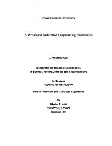
Simulation experiments have been carried out in a heterogeneous workstation environment. The load has been divided evenly between workstations without considering relative speeds of the workstations. The parallel simulation results are compared to the sequential time of the slowest workstation, Sun IPX . With large and computationally intensive applications, the execution time of the simulation can become a critical element of the problem solving. Distributed computing offers a solution, which allows faster completion of the simulation with commonly available hardware. Figure 6 presents simulation times which are achieved from the distributed simulation of the selected application in Diworse. It can be observed that the sequential simulation performs better with small call loads than the distributed one. This is due to the synchronization overhead, which is required for the distribution. As the call load increases, the computational benefits exceed the communication overhead and the distributed simulation in Diworse is superior compared to the sequential simulation. The effect of distribution can be easily seen when considering the high call loads. With three and four workstations, the distributed simulation performs in less than half of the sequential time whereas the speedup achieved with two workstations is much smaller. Three workstation simulation performs better than the four workstation model when the simulation load is sufficiently small. As the call load increases the benefits of the distribution overcome the synchronization overhead and the four workstation model performs fastest.
Runtime (s) 2000 1800 1600 1400 1200 Sequential 2 workstations
1000
3 workstations 4 workstations
800 600 400 200 0 100
200
300
400
500
600
700
800
Load (calls/h)
Figure 6. Sequential simulation compared to the distributed simulation times.
6. Conclusions In this paper, a distributed workstation environment Diworse is presented. Diworse is intended for the simulation of any application which needs a lot of computational power, e.g. cellular mobile networks. The simulated GSM network contained 27 cells. Results achieved with the parallel simulation of this GSM network have been compared to the sequential simulation of the same application. The results indicate that the distributed simulation in Diworse efficiently reduces the time required for simulation when the simulation model is large enough and sufficient simulation load is used. In these results, a distributed simulation with 3 and 4 workstations performs clearly better than the sequential or two-workstation simulation, as they benefit from the distribution of the computation.
References [Cha79] Chandy K and Misra J.: Distributed Simulation: A Case Study in Design and Verification of Distributed Programs, IEEE Transactions on Software Engineering, 1979, pp. 440-452. [Har92] Hara V. et al.: Parameter Estimation for Cellular Radio Networks, Proceedings of the INDIA COMM ´92, 1992, pp. 57-63. [Jef85]
Jefferson D.: Virtual Time, ACM Transactions on Programming Languages and Systems, Vol. 7, No. 3, 1985, pp. 404-425.
[Por96]
Porras J.: Application of Parallel Computing to the Performance Analysis and Simulation of Mobile Communication Networks, Licentiate thesis, http://www.lut.fi/~trappis/description.html, Lappeenranta University of Technology, 1996.