combined technique is verified by the application to test feeders to give better results. Different fuzzy decision-making forms are applied to the fuzzy modeling ...
206
IEEE TRANSACTIONS ON POWER SYSTEMS, VOL. 18, NO. 1, FEBRUARY 2003
Application of Fuzzy Logic for Reactive-Power Compensation of Radial Distribution Feeders S. F. Mekhamer, S. A. Soliman, M. A. Moustafa, and M. E. El-Hawary
Abstract—We introduce a new algorithm to determine the exact optimal solution for capacitor allocation in radial distribution feeders. Results of previous work using fuzzy and heuristic strategies on this feeder are compared with the exact reference solution. The effect of varying some parameters in the membership functions to obtain better results is discussed. Also, the effect of selection of parameters that should be used in the fuzzy modeling is investigated. The advantages of fuzzy and heuristic methods presented are combined in a new fuzzy-heuristic idea. This combined technique is verified by the application to test feeders to give better results. Different fuzzy decision-making forms are applied to the fuzzy modeling problem. Finally, a recommendation is made for the most efficient way to get a solution equal or very close to the optimal. Index Terms—Capacitor placement, fuzzy decision-making, fuzzy set theory, radial distribution feeder.
I. INTRODUTION
T
HE installation of shunt capacitors on radial distribution systems is essential for many reasons. Some of these reasons are power flow control, improving system stability, power factor correction, voltage profile management, and losses minimization. Therefore, it is important to find the optimal size and location of capacitors required to minimize feeder losses (power and energy), and the suitable time to switch on and off the capacitors. The solution techniques for the capacitor allocation problem can be classified into four categories [1]: analytical, numerical programming, heuristic, and artificial intelligence based (AI based). AI-based methods are now the most attractive methods. They include genetic algorithms (GAs), simulated annealing, expert systems, artificial neural networks, fuzzy set theory, and fuzzy logic. A survey of all capacitor allocation categories, especially the AI-based methods, has been presented in [1]. The area of interest in this paper is the work performed using fuzzy set theory [2]–[5] and some recent heuristic techniques [6], [7]. Reference [2] presents a fuzzy-based approach, method 1 in our paper, for capacitor placement for the 9-bus feeder defined in [8]. Two membership functions for real power losses and voltage sensitivity have been defined to reduce the effort of finding the optimal locations. The whole problem has been presented as a fuzzy-set optimization problem to minimize the real Manuscript received July 27, 2001; revised May 24, 2002. S. F. Mekhamer, S. A. Soliman, and M. A. Moustafa are with the Electrical Power and Machines Department, Ain Shams University, Cairo, Egypt. M. E. El-Hawary is with the Electrical and Computer Engineering Department, DalTech at Dalhousie University, Halifax, B3J 2X4, NS, Canada Digital Object Identifier 10.1109/TPWRS.2002.807037
losses and capacitor cost with voltage limit constraints. They used the intersection principle in fuzzy as the fuzzy decision to find the capacitor location then a variational method has been used to find capacitor sizes to attain minimum cost without violating the voltage constraints. In [3], method 2 in our paper, exactly the same procedures using the same feeder have been implemented but with two different membership functions. In fact, their membership functions for real power losses and voltage are the fundamental part of the membership functions that have been used in [2]. However, they have achieved relatively better results by introducing a certain constant in the real losses membership function depending on their experiences. In [4], method 3 in our paper, the authors used the membership functions forms of [2] but replaced the real losses by reacoperator) by tive losses and the intersection decision (using product decision. They used the product fuzzy decision to determine the location of the capacitors. To find the capacitor sizes, they used their analytical method that has been explained in [9]. This analytical method is based on differentiating a well-defined net saving function of power and energy losses with respect to capacitor size, thus obtaining the optimum capacitor size. Their method has been applied on the 34-bus feeder [9] with attractive results. Reference [5] presents a methodology to convert the analytical method stated in [9] from crisp solution into fuzzy solution by modeling the parameters using possibility distribution function, thus accounting for the uncertainties in these parameters. The generated fuzzy solution offers a more suitable means of evaluating the goodness of the results based on uncertain data. Reference [6] presents a heuristic strategy to reduce system losses by identifying sensitive nodes at which capacitors should be placed. These candidate nodes are determined by first identifying the branch in the system with largest losses due to reactive currents. Then the node, which contributes the largest load affecting the losses in that branch, is selected as the candidate node. The capacitor size is the value that gives minimum system real losses. A load flow is next performed to ensure no voltage violation. The method is repeated for the next candidate node until no further losses reduction is achieved. This method does not guarantee a minimization in the cost function or maximization in the net saving function. Reference [7] modifies the method of [6] to overcome this disadvantage so his technique attained good results but does not compromise between maximum net saving and voltage conpu, straints (i.e., in certain feeders the constraint may not be verified by this technique). However, the combination of heuristic methods [6] and [7] with fuzzy formulation,
0885-8950/03$17.00 © 2003 IEEE
MEKHAMER et al.: APPLICATION OF FUZZY LOGIC FOR REACTIVE-POWER COMPENSATION
method 3 and 4 in our paper, leads to better results, as it will take the voltage constraints into account when specifying the location of the capacitor using fuzzy decision making. Methods of [6] and [7] are explained in detail in Section II before the application of methods four and five. In this paper, only capacitor banks are to be used for reactive-power compensation and voltage profile improvement. The paper aims to review and implement previous methods. Then compare between them to select the best one. Also in this paper, we combine the heuristic ideas of [6] and [7] and fuzzy techniques. The different fuzzy decisions [10] formulae are studied to select the most appropriate one as the fuzzy decision for capacitor location. To show the closeness or remoteness from the exact solution after implementing these methods, a new algorithm to get this optimal capacitor allocation is presented, based on the 27-capacitor sizes mentioned in [2] for the simple 9-bus feeder.
207
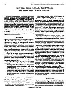
Fig. 1. Nine-bus test feeder.
TABLE I TEST FEEDER DATA
II. PROBLEM FORMULATION AND IMPLEMENTATION A. Fuzzy Set Theory Fundamentals If maps more than one element of to the same element in , then the maximum among their membership grades is taken. That is
The fuzzy set, which is a generalization of the conventional crisp set, extends the values of set membership from values in {0, 1} to the unit interval [0, 1]. A fuzzy set can be defined mathematically by assigning a value to each possible element of membership in the set. Some basic fuzzy operators are introduced in this section 1) The AND Operation (Intersection of Membership Functions): Let and be two fuzzy sets with membership funcand , respectively, and be the universal set. tions The membership function of the intersection (AND) is defined as
where are the elements that are mapped to the same . 5) Extreme of Fuzzy Functions: Let be a real-valued function in . Let be bounded from below by the infimum, and from above by the supremum, . with The fuzzy set
(1)
(6)
2) The OR Operation (Union of Membership Funcand be two fuzzy sets with membership tions): Let and , respectively, and be the functions universal set. The membership function of the union (OR) is defined as (2) 3) Product of Two Fuzzy Sets: The product of two fuzzy sets has a membership function defined by
(5)
is then called the maximizing set. There is another definition of the extreme of fuzzy functions, which are defined over a crisp domain. Since a fuzzy funcis a fuzzy set, say in , the maximum will genertion ally not be a point in but also a fuzzy set, which we shall .” The and the call the “fuzzy maximum of are increasing operations in . The maximum or minimum, respectively, of fuzzy numbers, denoted by and is again a fuzzy number. Let be to , defined over a crisp and finite a fuzzy function from is then defined as domain . The fuzzy maximum of
(3) 4) The
Extension Principle: Given a function and a fuzzy set in , where , the extension principle
states that
(7) A complete review on fuzzy set theory fundamentals and fuzzy decision making can be found in [10, Ch. 1, 2]. B. The Test Feeder
(4)
The 9-bus radial distribution feeder of [2] is taken as the test feeder. The rated voltage is 23 kV. The system is shown in Fig. 1. Table I shows the feeder data and feeder-line parameters.
208
IEEE TRANSACTIONS ON POWER SYSTEMS, VOL. 18, NO. 1, FEBRUARY 2003
TABLE II AVAILABLE THREE-PHASE CAPACITOR SIZES AND COST
TABLE III POSSIBLE CHOICES OF CAPACITOR SIZES AND COST/KVAR
C. Problem Formulation [2], [3] The objectives of capacitor placement are to reduce the power loss and keep voltages within prescribed limits with minimum cost. The total power loss is given by (8) Considering investment cost, there are a finite number of standard capacitor sizes that are integer multiples of the smallest size . The cost per kilovar varies from one size to another. Generally, large sizes are cheaper than smaller ones. Let the maximum permissible capacitor size be limited to
D. Method 1 [2] In [2], the exponential membership functions of voltage and real losses are given by (12)
(9) where is an integer. Then, at each selected location, there be the correare sizes to choose from. Let sponding capital investment per kVAr. Assuming that only capacitor banks are used for voltage excursions, the cost function can be selected as (10) is the cost per power loss ($/kW/year) and represents the selected buses. The objective function is to be minimized subject to
where
(11) is selected to be U.S.$ 168/kW [8], and For the test feeder, p.u and p.u. Comthe voltage limits are mercially available capacitor sizes with U.S.$/kVAr are used in the analysis. Table II shows an example of such data provided by a supplier for 23-kV distribution feeders. For reactive-power should not compensation, the maximum capacitor size exceed the reactive load (i.e., 4186 kVAr). This results in 27 possible capacitor sizes shown in Table III with corresponding cost/kVAr [11]. The values of the 27 choices are derived from Table II by assuming a life expectancy of ten years (the operating costs are neglected). Applying the load flow program on this feeder before compensation, the cost function and the total power losses are U.S.$ 131 675 and 783.8 kW, respectively. The maximum and minimum bus voltage magnitudes were 0.9929 and 0.8375 p.u., respectively, where the voltage of the substation (bus number 0) is assumed to be 1 p.u., thus we generally have p.u.. In the next section, the methods discussed earlier are applied to this feeder.
where
is the weighting factor and
is the voltage of node
(13) is the power loss between buses and and is the total power loss. The fuzzy decision membership function is the intersection, thus
where
(14) The solution algorithm can be summarized as follows. 1) Perform the load flow program to calculate bus voltages and sectional losses. 2)Find the membership functions of voltage, losses, and decision for the fuzzy sets of voltage, power loss, and decision. 3) Identify the candidate node at the bus with the lowest membership function (bus ). with size 4) Install a capacitor at bus that varying in integer steps. Select has the lowest cost without violating the constraints. at bus and perform the 5) Add this load flow again. Exit if there is no voltage improvement, otherwise, go to step 2. buses have been chosen 6) Assuming that for placing new capacitors, adjust the ) in integer steps first capacitor (
MEKHAMER et al.: APPLICATION OF FUZZY LOGIC FOR REACTIVE-POWER COMPENSATION
209
TABLE IV RESULTS FOR ALL METHODS APPLIED TO THE 9-BUS FEEDER INCLUDING ORIGINAL DATA AND THE EXACT SOLUTION RESULTS
while keeping others fixed. Select for the first one that has the lowest cost . without violations. Repeat for 7) Repeat step 6 if the cost function still decreases. If no significant cost reduction can be achieved, the optimal solution is reached. Implementation of this method leads to a reduced cost function of U.S.$ 119 736 and 707-kW losses and a voltage impu. The results are summarized provement of in Table IV. E. Method 2 [3] The only difference between this method and method 1 is the shape of the membership functions of voltage and power loss. They are defined as (15)
(16) is a constant whose value is determined by experience. where The implementation of this method leads to better results; voltage U.S.$ 119 420, 704.88-kW losses and upper and lower limits. The results are summarized in Table IV. F. Modifications of Methods 1 and 2 For method 1 when a modification is made to the weighting factors of the membership functions so that an importance of 20 to 30% is given to the nodal voltage effect and an importance of 70 to 80% is given to the real losses effect, the results improve. The cost function is reduced to U.S.$ 118 296 and
697-kW losses and voltage upper and lower limits. is On the other hand, for method 2, when the constant taken to be 70 to 80% of total real losses, the results improve. The cost function is reduced to U.S.$ 118 562 and 699-kW voltage upper and lower limits. losses and The results of these modifications in methods 1 and 2 are summarized in Table IV. G. Method 3 In this method [4], the real loss membership function is replaced by a reactive-loss membership function of the same exponential form as [2]. The weighting factors are set to 0.3 and 0.7 for the voltage- and reactive-loss membership functions, respectively. The fuzzy decision function is the product instead of the intersection of [2], that is (17) In our implementation here, cost function and the same previous algorithm of solution of methods 1 and 2 are used instead of the analytical method of [4]. The results are better, the cost is reduced to U.S.$ 117 330, 689-kW losses and voltage upper and lower limits. This means that the reactive-loss membership is more appropriate than that of the real loss. The results are summarized in Table IV. H. Methods 4 and 5 First, we summarize the idea of the techniques used in [6] and [7]. The total active power loss for a distribution system with branches is given by (18) are the current magnitude and resistance, rewhere and spectively, of branch . The branch current can be obtained from
210
IEEE TRANSACTIONS ON POWER SYSTEMS, VOL. 18, NO. 1, FEBRUARY 2003
the load flow solution. This current has two components—active ( ) and reactive ( ). Thus, the system losses can be written as
The method of [7] is exactly the same as [6] but the capacitor size is defined as the value that maximizes the cost reduction. This means is evaluated from
(19)
(23)
To find the change in system losses due to the reactive load at node , we find the system losses without this load as
In our presented method, method 4, the idea of [6] is modified; first the capacitor locations are found using the same fuzzy technique of method 3. Then, instead of using the local variational method explained in the algorithm of method 1 for the three previous methods, we use the idea of [6] to find the capacitor size as the size that causes minimum total real losses (if the resulting capacitor size is not standard, we take the nearest standard value using Table III). This, in fact, is better than the implementation of the technique of [6] completely. This is simply because capacitor location based on the fuzzy decision compromises between the importance of loss reduction and voltage constraints. Implementation of this method gives U.S.$ 117 571 for cost function, 692-kW losses voltage upper and lower limits. and Results are summarized in Table IV. Method 5 is the same as method 4 except that, after finding the capacitor location, we use the idea of [7]; that the capacitor size is the one that gives minimum cost function (instead of minimum real losses used in [6]). As expected, the results are better than those of method four. The results are U.S.$ 117 479 voltage upper and 691.6-kW losses, and and lower limits. The results are summarized in Table IV.
(20) is the reactive current component of the load set at where ) due node . Subtracting (20) from (19), the loss change ( to the reactive load at can be obtained as (21) These expressions are based on the shortest way between the means the node of interest and the substation (e.g., sum of all resistances of the shortest path connecting the substation and node ). Now we can summarize the algorithm used in [6] in the following points. 1) Perform the load flow solution for the original feeder to get the branch currents and other necessary data. 2) Apply (21) for each node in the system, to find the change in system losses caused by each reactive load. Arrange the nodes in descending order according to (21) to identify the sensitive nodes. 3) Select the node, say node , of load that causes the maximum power loss change to be the candidate node where a capacitor should be placed. 4) Install a capacitor at this sensitive node. The capacitor size is the value that minimizes the total system losses. That is (22) If the value obtained for capacitor size is not a standard size, take the nearest standard size and place it at . 5) Perform the load flow again to check for possible voltage violation. If any node voltage exceeds the permissible limits ( 5 ), the capacitor is disconnected and the node having the next largest reactive load current on the section of the high losses is considered as the sensitive node. Then go to step 4.
I. Exact Solution Although method 3 offers the best results, methods 4 and 5 involve less effort. The reason is that the capacitor size in methods 1, 2, and 3 is based on the local variational method, which is cumbersome if the feeder topography is not simple, unlike the test feeder. For this reason, it is recommended that method 5 is the best method. However, the question now is, from the results of all previous methods, how far is the solution from the exact optimal? To answer this question, a new program is created to obtain the exact solution which is possible for this simple feeder, based on the 27 sizes (choices) of Table III and the cost function and voltage constraints defined in (10) and (11), respectively. The new algorithm is summarized as follows. at bus 1) Assume that we should put number one. Try all of the 27 values of at this bus. For each value of , perform the load flow program and evaluate that gives the cost function. Record minimum cost and record this cost also. 2) Repeat step 1 for all buses. Then seat the bus (bus K1) that lect to put has the lowest minimum cost function. placed at bus K1, re3) With optimal peat steps 1 and 2 to select the next candidate bus (K2) where the next optimal will be placed.
MEKHAMER et al.: APPLICATION OF FUZZY LOGIC FOR REACTIVE-POWER COMPENSATION
211
TABLE V DATA OF THE SECOND TEST FEEDER
Fig. 2. One-line diagram of test feeder 2.
4) With and placed at buses K1 and K2, repeat steps 1 and 2 and so on until candidate buses are exhausted. 0.9, 5) If the minimum voltage is still of the candidate node try to increase that is very far from the substation. This will increase the voltage such that p.u .
The implementation of this procedure, using Matlab 5.2, to the test feeder resulted in a cost of U.S.$ 117 095 and 686-kW p.u. The results are summarized losses with in Table IV. From this experiment, it is clear that method three is very close to the exact but practically the combination of fuzzy technique with the technique of [7] is recommended as it avoids the variational methods, which will be cumbersome for the case of practical feeders. It is noted that the results presented in Table IV for the modified methods (modified method 1 and 2), methods 3, and combined methods (4 and 5) are better than those of the methods presented in Table III, case (a), of [11]. Also, the loss reduction of the methods presented is higher than the loss reduction obtained by the numerical programming method cited in Table III; test B of [12], for the same voltage constraints, which support the modifications and methods presented in our paper. J. Another Test Feeder For the sake of conclusions support, the methods discussed before are applied to another 34-bus radial distribution test system. This test system has a main feeder and four laterals (subfeeders). A single line diagram is shown in Fig. 2. The data of this feeder are presented in Table V. The system voltage is 11 kV. Before compensation, the cost is U.S.$ 37 212, this is based on the previously defined cost function, the active and reactive losses are 221.5 kW and 65.04 kVAr, respectively, . and the voltage limits in per unit are The minimum voltage is at node 5_11. A part of Table III is to 19), as the capacitor size used for this feeder (from should not exceed the total reactive load of the system. The implementation shows that the main feeder and the subfeeder connected to node 5 only need compensation.
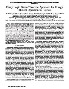
Fig. 3.
Cost function for the five methods applied to feeder 2.
The results of the modified methods 1 and 2, and methods 3, 4, and 5 are presented in Figs. 3–5. The same conclusion that has been made from the first feeder could be extracted from this feeder as well. The combined fuzzy-heuristic technique (method 5), which is a new idea, gives the best cost and loss reductions with a significant improved voltage profile. Also, the results of loss reduction of method 5 are better than those of the heuristic methods of [6] and [7], and the analytical method of [9], and even better than that of the fuzzy expert system (FES) presented in [13], with
212
Fig. 4.
IEEE TRANSACTIONS ON POWER SYSTEMS, VOL. 18, NO. 1, FEBRUARY 2003
Active losses for the five methods applied to feeder 2.
Many aggregators, which have been mentioned in [10], have been investigated here using the test feeders for the previously mentioned methods. The FUZZY AND suggested by Werners, defined in (24) and the aggregation by the convex combination between and operators, defined in (25), seem to be good for the fuzzy capacitor location situations for radial distribution feeders. However, an important effective note could be and the product extracted from all aggregators is that the operators are still the most effective if their advantages are used together. In other words, while taking the decision from the AND or the product, we should take advantages of both simultaneously. This could be done if we always study two respective decisions instead of the first decision only. To explain this procedure: Asoperator, sume the decision memberships , based on the in an ascending order are 5,7,4, …etc. This means that the candidate node, according to the fuzzy algorithm steps, is node 5 and we should place a capacitor at this node of size dependent on the method used. Based on our experience, from the application to several feeders, the decision memberships , based on the product operator, in an ascending order will also start with opernode 5 or node 7, which is the second node using the or the product operator, we ator. Thus, generally using the should try to place a capacitor at the first candidate node, node 5, and then at the second candidate node, node 7, instead, and then select the decision of them that leads to lower cost (24) (25) where ,
Fig. 5.
Minimum voltage at node 5_11 for the five methods applied to feeder 2.
the same advantage of compromising between the voltage and losses importance. K. Fuzzy Decision Making In conventional set theory and binary logic, the definitions of intersection and union are uniquely defined. But in fuzzy set theory and fuzzy logic, there are many proposed definitions. The reason for this is simple: Many operators behave in exactly the same manner if the degrees of membership are restricted to the values 0 or 1. If this restriction is relaxed, the operators lead to different results. opIn methods 1 and 2, the fuzzy decision is the AND ( erator) intersection while it is the product for method 3. However, when the product decision is applied with methods 1 and 2, the results are worse than the original results for the first feeder while they were better than original results for the second feeder. It can be concluded from this that a good fuzzy decision is not always obtained by the AND or the product for all situations. Bellman and Zadeh indicated in [14] that the min-interpretation of the intersection might have to be modified depending on the context. Zimmermann [15] showed that the decision should be defined by its membership function that is based on appropriate, possibly context-dependent “aggregators” (connectives).
. III. CONCLUSIONS
The following points summarize the new algorithm, methods, and ideas presented in this paper. 1) The influence of reactive losses in the membership function is more effective than the influence of real losses. This is obvious from method 3 whose results are very close to the optimal solution. 2) The degree of importance (weighting factors values) that may be given to the parameters in the membership functions is effective and could improve the results. 3) The combination of fuzzy solution and the technique that is based on the heuristic strategy of [7] is the recommended technique (i.e., method 5). The fuzzy decision will be as in method 3 to find the capacitor location that always compromises between losses and voltage constraints. The capacitor size is chosen as [7] based on minimum cost function instead of variational methods. This technique of fuzzy-heuristic combination is a new idea presented in this paper and leads to results better than previous analytical methods. 4) The AND and the product operators could be very effective as fuzzy decisions for the capacitor placement of radial distribution feeders for all situations if, while using one of them, we try to exploit both of their advantages.
MEKHAMER et al.: APPLICATION OF FUZZY LOGIC FOR REACTIVE-POWER COMPENSATION
5) New software has been presented; this software is useful to check the validity and effectiveness of capacitor allocation techniques when applied to simple test feeders. REFERENCES [1] H. N. Ng, M. M. A. Salama, and A. Y. Chikhani, “Classification of capacitor allocation techniques,” IEEE Trans. Power Delivery, vol. 15, pp. 387–392, Jan. 2000. [2] H. Chin and W. Lin, “Capacitor placement for distribution systems with fuzzy algorithm,” in Proc. 1994 IEEE Region 10’s Ninth Annu. Int. Conf., vol. 2, pp. 1025–1029. [3] C. Su and C. Tsai, “A new fuzzy-reasoning approach to optimum capacitor allocation for primary distribution systems,” Proc. IEEE Int. Conf. Ind. Technol., pp. 237–241, 1996. [4] H. N. Ng, M. M. A. Salama, and A. Y. Chikhani, “Capacitor placement in distribution systems using fuzzy technique,” in Proc. Canadian Conf. Elect. Comput. Eng., vol. 2, 1996, pp. 790–793. [5] H. N. Ng and M. M. A. Salama, “Fuzzy optimal capacitor sizing and placement,” in Proc. Canadian Conf. Elect. Comput. Eng., vol. 2, 1995, pp. 680–683. [6] T. S. A. Salam, A. Y. Chikhani, and R. Hackam, “A new technique for loss reduction using compensating capacitors applied to distribution systems with varying load condition,” IEEE Trans. Power Delivery, vol. 9, pp. 819–827, Apr. 1994. [7] M. Chis, M. M. A. Salama, and S. Jayaram, “Capacitor placement in distribution systems using Heuristic search strategies,” Proc. Inst. Elect. Eng., vol. 144, no. 3, pp. 225–230, 1997. [8] J. J. Grainger and S. H. Lee, “Optimal size and location of shunt capacitor for reduction of losses in distribution feeders,” IEEE Trans. Power App. Syst., vol. PAS-100, pp. 1105–1118, Mar. 1981. [9] M. M. A. Salama and A. Y. Chikhani, “A simplified network approach to the VAr control problem for radial distribution systems,” IEEE Trans. Power Delivery, vol. 8, pp. 1529–1535, July 1993. [10] M. E. El-Hawary, Electric Power Applications of Fuzzy Systems. Piscataway, NJ: IEEE Press, 1998. [11] Y. Baghzouz and S. Ertem, “Shunt capacitor sizing for radial distribution feeders with distorted substation voltages,” IEEE Trans. Power Delivery, vol. 5, pp. 650–657, Apr. 1990.
213
[12] M. E. Baran and F. F. Wu, “Optimal sizing of capacitors placed on a radial distribution system,” IEEE Trans. Power Delivery, vol. 4, pp. 735–743, Jan. 1989. [13] H. N. Ng, M. M. A. Salama, and A. Y. Chikhani, “Capacitor allocation by approximate reasoning: Fuzzy capacitor placement,” IEEE Trans. Power Delivery, vol. 15, pp. 393–398, Jan. 2000. [14] R. E. Bellman and L. A. Zadeh, “Decision-making in a fuzzy environment,” Manage. Sci., vol. 17, no. 4, pp. 141–164, Dec. 1970. [15] H.-J. Zimmermann, Fuzzy Set Theory and its Application, 2nd ed. Norwell, MA: Kluwer, 1990, ch. 12, pp. 241–272.
S. F. Mekhamer, photograph and biography not available at the time of publication.
S. A. Soliman, photograph and biography not available at the time of publication.
M. A. Moustafa, photograph and biography not available at the time of publication.
M. E. El-Hawary, photograph and biography not available at the time of publication.