IEEE TRANSACTIONS ON ROBOTICS AND AUTOMATION, VOL. 18, NO. 4, AUGUST 2002
487
Short Papers_______________________________________________________________________________ Architectural Models for Global Automation Systems Davide Brugali and Giuseppe Menga
Abstract—Designing automation systems, as in most engineering endeavors, is primarily an architectural problem, involving hardware and software components. The objective of this paper is to introduce the concept of software architecture and styles in designing automation systems, and to describe an object framework for the development of global automation systems. Index Terms—Control architectures, design patterns, distributed systems, factory automation.
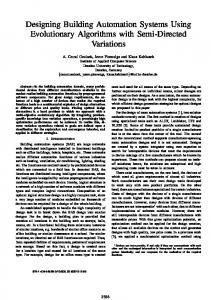
Fig. 1. Global automation platform.
I. INTRODUCTION Globalization is bringing forth a variety of new opportunities that in a few years will completely revolutionize the vision we have today of an industrial production system and its automation processes. The Internet will connect factory automation systems with customers and providers to build the so-called Virtual Organization [9]. Still more importantly, the concept of factory automation is spreading throughout the territory. Processes internal and external to the factory are rapidly being linked to each other (traffic and environment monitoring, mass mobility, and waste management). Hence, the definition of “Global Automation Systems.” The new emerging and confluent tendencies, “embedding the Internet” [4] (i.e., pursuing the interconnection of any kind of physical and virtual devices through the Internet) and “ubiquitous computation,” reduce the significance of the computing center as the core of any organization. This inevitable technological evolution naturally poses new requirements and challenges in design. It means defining new reference architectural models that are sufficiently flexible and powerful to be used at multiple levels of a global automation system, from the interfactory logistics of geographically distributed enterprises, to the coordination of production in a factory, down to monitoring and controlling production shops or coordinating autonomous mobile robots inside a factory. The innovative aspect of our research is the definition of an Internet-based software framework, which is made up of a communication infrastructure logically structured as an information bus and of a uniform architecture (Fig. 1). The framework is sufficiently flexible to be used at multiple levels, ranging from the monitoring and control system for a single production cell [the virtual Supervisory, Control, and Data Acquisition system (SCADA)], to the integration of the supply chain of a multinational corporation (the virtual factory), up to the construction of a global organization. We call this distributed framework a Global Automation Platform (GAP). Conceptually, GAP is similar to the open platforms in the network operating systems, but it has other contents and scopes.
It addresses two main aspects related to the innovative adoption of Internet in automation systems, and the logical interconnection of manufacturing centers, territorial services, and customers. In this paper, we document the architectural models that are enforced by the GAP framework in the form of Design Pattern [5]. The most general definition of a pattern is a literary form that describes a context, a design problem that occurs in that context, and a solution to the problem. In object-oriented software engineering, the solution of a pattern is typically a way of structuring a cluster of objects and their interactions. The whole set of patterns for a specific application domain, together with their structuring principles, becomes a high-level language, called a pattern language [2]. There is an intriguing relationship between the concept of framework and pattern language. In our view, the pattern language generates the framework that, thereafter, offers the components for the pattern implementations [3]. The paper is organized as follows. Section II presents the pattern language that documents the architectural models of the GAP infrastructure. Section III describes the software components that derive from the adoption of the pattern language in global automation systems. Section IV exemplifies a distributed scheduling system. Finally, Section V draws the relevant conclusions.
II. PATTERN LANGUAGE To build software applications for global automation, three main issues must be addressed: interfacing peripheral devices to the network, controlling resources in real time, and scheduling resources at different time horizons. While developing automation systems in several domains [1], [3] we have identified the following design patterns. A. Pattern 1: Autonomous Control Modules
Manuscript received December 1, 2001. This paper was recommended for publication by Associate Editor Y. Narahari and Editor N. Viswanadham upon evaluation of the reviewers’ comments. This work was supported by the Hewlett-Packard Internet Philanthropic Initiative–Next Generation Internet, 1999. D. Brugali is with the School of Engineering, University of Bergamo, 5-24044 Dalmine, Italy (e-mail:
[email protected]). G. Menga is with the Department of Automatic Control, Politecnico di Torino, 24-10129 Torino, Italy (e-mail:
[email protected]). Digital Object Identifier 10.1109/TRA.2002.802939
Context: Internet is ubiquitous, and potentially every distributed computing device could be connected into a truly worldwide network linking the physical world of sensors and actuators and the virtual world of information utilities and services [12]. In reality, embedding the Internet into the huge variety of real devices and applications calls for a technology which allows distributed resources to be flexibly combined, and their activities coordinated. GAP provides a uniform representation of the software control modules that manage the physical devices, the
1042-296X/02$17.00 © 2002 IEEE
488
IEEE TRANSACTIONS ON ROBOTICS AND AUTOMATION, VOL. 18, NO. 4, AUGUST 2002
Fig. 3. Peer-to-peer interconnection of control modules.
Fig. 2. Model of an autonomous control module.
monitoring and control of workstations, the interfactory cooperation, and the interaction with the human operators. Problem: Control modules should have the capability of: 1) encapsulating computational resources and the services that manipulate them; 2) executing more than a single service concurrently (e.g., a workcell produces more than one single lot of pieces at the same time); 3) offering alternative ways to exploit their functionality (e.g., one client invokes a service synchronously, while another client invokes the same service asynchronously); and 4) implementing autonomous decision-making capabilities. Solution: These requirements are satisfied by the model depicted in Fig. 2 (the boxes with thick borders represent components of the framework, the other boxes are specializations). The framework offers four classes to support the model: the Service, the Server, the Protocol, and the Resource. Service objects represent independent sequential execution processes. A Service object always belongs to a unique Server owner, it embeds the dynamic specification of its activity, it has internal data, it maintains a symbolic state value, and broadcasts events with the incoming state name every time a state transition occurs. The Service, as in the case of the class Cutting in Fig. 2, has to be redefined for every concrete specification that implements the logic of a manufacturing operation. Clients can access a given Service according to several interaction protocols. The framework offers the abstract class Protocol that has to be specialized for every concrete protocol. For example, Protocol objects can represent asynchronous, synchronous, or deferred-synchronous (as in Fig. 2) service requests. It can also represent exclusive (e.g., for writing) or shared (e.g., for reading) access to the server’s resources. The separation of services from protocols enhances the flexibility of the control modules, as they are seamlessly adaptable to a new client’s requirements. Server is the base class of every control module (e.g., the Machine). It encapsulates a collection of Service objects and has to be redefined in order to encapsulate specific resources, or other subServers. The Server class offers the method doService( ) for protocol negotiation and service invocation. When a client calls this method, a new Service is created and initialized to use the private resources of the server; the client receives an instance of class Protocol. Server also subscribes to state transition events generated by its services and relays them externally using the Broadcast/Listener mechanism [3]. Resource is a class that offers abstract methods which are used to read and write the state of a resource component in/from a persistent storage and are implemented in every subclass. The Resource class offers two methods for event subscription and event notification.
The Server is a specialization of Resource and, at the same time, encapsulates a collection of resources. This solution is similar to the Pattern Composite in [5] and allows the recursive interconnection of control modules. Example: Automation at the physical process level has been traditionally represented by SCADA systems, which are built on high-performance fieldbus networks. In a new conception, an Internet-based SCADA has still to be invented. Let us consider the problem of forecasting and controlling the traffic flow on a motorway. The motorway is a sequence of one-way adjacent sections, each one holding one toll station with lateral entrance/exit. The control problem consists in regulating the input flow at all entrance gates in order to minimize a measure of all transit times by reducing the traffic jams. Each section is an autonomous control module with its own measures through in-road sensors of traffic speed and flow, and its own control of the entrance gate flow through semaphores. The overall motorway control system finishes up as a flat interconnection of local control modules that have a cellular structure (each module exchanges information with only its two neighbors) as depicted in Fig. 3. Each Server physically resides in place, which corresponds with a motorway section. It collects traffic data from the sensors, propagates its own traffic forecasts (exchanging this information with its neighbors), and controls the semaphores at the entrance gate. The Servers instantiate Protocol/Service pairs to handle their synchronization. Implementation: The GAP framework implements the Client/Server communications paradigm using the Remote Method Invocation (RMI) mechanism provided by Sun’s Java Development Kit. It is a standard support to proxy-based code mobility. The client receives from the server a Protocol object that implements the interaction logic used to access a specific category of services. Once instantiated on the client’s side, the Protocol object communicates with the server via sockets. The server instantiates the Service object requested from the client and sets up the communication between the client-side Protocol object and the server-side Service object. B. Pattern 2: Resource Allocator Context: Autonomous control modules offer multiple services that use internal resources to perform specific tasks concurrently. Some tasks (e.g., to transport pieces from a store to a machine) require exclusive access to shared resources (e.g., the cart in a workcell). The tasks are usually related by temporal constraints (i.e., precedence). The (optimal) allocation of resources to tasks over time is a scheduling problem. In the global automation context, it ranges from relatively classical shop floor scheduling problems, for which many exact and heuristic algorithms exist, to higher level interfactory negotiation problems, for which decentralized solutions are still being investigated. Problem: Autonomous control modules should have the capability of managing the temporal constraints regarding the execution of their services, by offering the following functionalities: 1) specify when a service should be executed;
IEEE TRANSACTIONS ON ROBOTICS AND AUTOMATION, VOL. 18, NO. 4, AUGUST 2002
Fig. 4.
Classes used for resource allocation.
2) identify conflicts in resource usage; 3) allow clients to resolve service request conflicts. Solution: The framework provides the class Allocation, which extends the class Protocol with two additional methods. 1) Integer book (Service s, Time b, Time e) creates a new instance of Reservation and stores it in a list of the Server class. It returns the reservation identifier. 2) Void release (Integer reservationID) removes a specific reservation from the server’s list. The framework provides the class Reservation, which is inherited from the class Service (see Fig. 4) that has two basic attributes. Start and end represent the period of time when the client needs to use the requested service exclusively. The class Reservation can be extended with additional attributes to represent, for example, priorities, deadlines, and costs associated with deadline extensions. Instances of class Reservation are executed by the Server, and are set up to communicate with instances of Allocation on the client side. The framework provides the class Scheduler, which has to be specialized to implement specific scheduling policies. Whenever a client books a resource, the Scheduler revises the assignment in time of resources to clients. If it finds conflicts among the clients’ requests, it might simply inform the clients, or it might try to find a new assignment that resolves the conflicts. The Scheduler communicates with the Clients through their Allocation objects by raising notification events. Example: Let us consider two application scenarios for this pattern. Resource Manager. The pattern is applied to the autonomous control modules that have to schedule manufacturing resources. The visibility of each control module is limited to its private resources, which it allocates to its clients according to local policies. The Scheduler takes into account the deadline of each request and the cost of extending each deadline. Process Manager. The pattern is applied to control modules (we call them Processors) that do not manage resources, but represent the manufacturing processes (sequences of jobs) that the lots of pieces must undergo (one service for each lot). The Resource Managers schedule their activities by asking the Processors to allocate job operations. The Processor knows the sequence of operations that should be performed on a lot of pieces and accepts reservations accordingly. Implementation: For the implementation of specific scheduling algorithms, the interested reader can refer to [10]. C. Pattern 3: Mobile Services Context: Traditionally, the development of integrated enterprise applications has been focused on shared data and local processes (e.g., Inventory Management, Planning, Supervision, and Control). With the introduction of the Internet, however, some processes become shared across the organization (e.g., Order/Supply management), and operate mostly using local data [6]. The Internet offers customers and providers the possibility of operating directly on the partner’s facilities.
489
Problem: Code mobility makes it possible to transfer not only data but also first-class objects, called mobile objects, over the network. The mobile code paradigm allows the client to provide the code that operates on the server’s resources. In the GAP platform, we want to extend the model of the control module so as to support the mobility of its services. Solution: The class diagram depicted in Fig. 5 describes the interaction between two remote control modules. The Client establishes a partnership with the Server by sending to its side a mobile object that represents a remote placeholder of the Client’s functionality. MobileService is the basic class that implements the mechanisms to serialize an object’s state before it is dispatched over the network and to restore its execution when it is received at destination. This class should be extended to implement the behavior of a specific mobile service, and to specify the resources that it will use on the destination side. The class ProxyManager extends Server and implements the mechanisms for creating, transmitting, and receiving mobile services. It offers the methods createMobile( ) and dispatch( ) that can be invoked by the Client. The method createMobile( ) receives the indication regarding which mobile service should be instantiated. When the ProxyManager at the Provider side receives a mobile service, it sets it up to access the remote resources. The Client interacts with the remote mobile service via the MonitoringService object. Example: A typical interaction between factories is when a customer requests raw or semifinished materials from one supplier. The request triggers the supplier’s planning system, which attempts to accommodate the incoming request and return, as quickly as possible, lead times and costs for the required product. In this example, the customer and the supplier are represented by two remote control modules, each of which implements local Enterprise Resource Planning (ERP) functionalities. The customer ERP instantiates a mobile service that is in charge of the remote management of the events (e.g., delays in the order processing) raised at the supplier side. The mobile service is set up to solve specific problems on the supplier’s side autonomously and to report specific events on the customer’s side. Implementation: The IBM Aglet [7] is an example of a framework that supports code mobility to implement mobile objects. III. FRAMEWORK COMPONENTS The designers of global automation systems adopt the pattern language to build applications that offer specific functionality and coordinate the activities of the real system. The GAP framework supports the pattern language as it implements the high-level objects, which represent the major abstractions found in the problem domain (the Server, the Resource, the Scheduler, etc.). However, the adoption of the pattern language in an increasing number of applications makes it possible to develop more concrete components within the framework, which provide solutions for the difficult problems. In the following, we document the architectural models of three framework components. They support three levels of separation of concerns. The Device Wrapper makes a control application independent of the technology used to interface real devices; the Connection Broker makes control services transparent to the availability and network location of their servers; the Facilitator abstracts from the physical networking of clients and servers, and allows the logical interconnection of distributed resources. A. Device Wrapper Embedding the Internet into manufacturing devices such as robots, transports, and milling machines poses the problem of event-driven communication.
490
Fig. 5.
IEEE TRANSACTIONS ON ROBOTICS AND AUTOMATION, VOL. 18, NO. 4, AUGUST 2002
Model of the Proxy Manager.
Fig. 7.
Model of the connection broker.
B. Connection Broker Fig. 6. Classes used to virtualize data and events.
Device Control Modules receive stimuli from a physical device, which responds to them by updating its state and giving feedback. Stimuli and feedback are modeled as events, thus, device control modules are event-driven systems that wrap the physical device so as to provide an Internet access point to other networked control modules. Developing object-oriented software for event-driven systems presents some particular difficulties. The physical device does not have logical variables in the control module’s address space that represent its state, such as the control registers (physical variables) of a programmable logic controller (PLC). In the same way, the logical events of the software systems are just communication mechanisms between autonomous control modules. Software objects that subscribe to events from a Device Control Module must receive those logical events, which correspond to external stimuli from the physical device. This means a bridge is needed between the logical and the external variables and events. The framework offers the classes DataPoint and Event. The class DataPoint (Fig. 6) maps the peripheral state variables to the logical variables of the device control module. This class extends the Resource class in order to make the state of the physical device persistent. In addition it offers the methods externalize( ) and internalize( ) so as to write/read data in/from the device’s registers. The class Event encapsulates a physical stimulus and offers the method subscribe( ), so as to allow client objects to receive logical events in response to physical stimuli, and the method notify( ) to generate a stimulus to the device in response to a logical event. Event objects have a reference to the software objects that should raise the logical events when the physical stimuli occur. Device wrappers improve communication performance by exploiting the code mobility mechanism. Client modules can dispatch mobile services to the device control module that embeds the client’s control logic.
Distributed resources are free to appear and disappear on the Internet and the mapping of requests to services is highly dynamic. One of the basic problems is finding what service is available from which server. Since it is obviously not feasible to broadcast the information that a resource has appeared or disappeared on the Internet, specific components take on the role of broker. A broker is a component that has a well-known name and location within a subnetwork and allows new resources to advertise their services. Control modules can query the broker for the available resources. The GAP framework offers the Connection Broker component, a specific control module (see Fig. 7) that inherits from the Resource class. The Broker maintains a collection of Service templates and Protocol templates that servers have registered and clients can query. A Service template is an object that has the same interface as a specific subclass of Service, but it does not implement the service’s logic. The same is true for Protocol templates. For example, the Broker might maintain an instance of a Cutting service template and of a Deferred protocol template. The Broker maintains a collection of Server proxies, one for each control module that has registered its services. The Broker records the associations between protocol templates, service templates, and server proxies in a table. It implements a template-matching algorithm that allows clients to find a server that offers a given service and supports a given protocol. It exports three methods. 1) Void register (Service s, Protocol p) allows clients to register their services and protocols, which specify usage constraints (e.g., period of availability). 2) Void expire (Service s, Protocol p) allows clients to withdraw their services. 3) Server query (Service s, Protocol p) returns the proxy of one sever that supports a specific service and protocol. This method should be redefined if the broker implements specific policies to select one out of several servers that can provide the same service.
IEEE TRANSACTIONS ON ROBOTICS AND AUTOMATION, VOL. 18, NO. 4, AUGUST 2002
Fig. 8.
491
The model of the facilitator.
The Broker raises three events (in addition to those raised by the registered control modules). 1) ServiceIn: A new service has been registered. 2) ServiceOut: An old service has been cancelled. 3) ServiceChanged: Service properties have changed. The Broker can implement global scheduling algorithms to assign resources to the clients and balance the load of each server control module. Nevertheless, the Broker can become a bottleneck and a centralized point of failure. C. Information Bus Facilitator A global automation system is physically structured (for efficiency and security reasons) in a hierarchy of subnetworks that group control modules according to their physical location. Usually, a subnetwork interconnects the resources of a physical factory, a department, or a production cell. In a global automation system, business processes cut across the physical boundaries of factories and departments. Virtual organizations and virtual factories represent logical networks of geographically distributed resources. The GAP framework supports the concept of Information Bus as a flat interconnection of control modules that logically breaks up the physical hierarchy of network and subnetworks. For example, a supply chain builds on an information bus that interconnects the ERP modules of geographically distributed factories. The GAP framework provides the Facilitator control module (see Fig. 8) that takes on the role of name server, message router, and gateway between subnetworks. 1) Name Server. Each control module in the global information system is represented by a symbolic name that is prefixed with domain names so that the path to the control modules through the domains is given. This solution has the advantage of decoupling the identity of control modules from their physical locations. The Facilitator is responsible for the mapping of symbolic names to network addresses. Control modules can query the local Facilitator to get references (the proxy) to remote control modules. For example, the Client ERP can get the reference to the Provider ERP. 2) Router. A local Facilitator does not record the logical and physical addresses of all the control modules in the global information system. Instead, it is able to route queries from the client control module to the Facilitator that records the network address of the remote control module. In particular, the Facilitator records the network address of the Broker in its subnetwork. For example, the Broker in a workcell might have the following symbolic name: CustomerFactory.Shop.WorkCell.Broker. 3) Gateway The Facilitator filters the incoming requests for services and the broadcasting of events generated by the control modules of the subnetwork. This guarantees that control modules external to the subnetworks can access only specific resources
and listen to specific events. A variety of mechanisms can be implemented to filter access to a subnetwork: at the level of message packets, of message criptograpy, of client authentication. The Facilitator inherits from the Resource class and implements a Routing Table to handle the routing of messages internally to its subnetwork. The Facilitator implements the method connect( ) that accepts the symbolic name of the remote server as parameter, and creates two instances of class Channel (a subclass of Service): one within the local Facilitator, whose reference is returned to the invoking Client, and one within the Facilitator of the remote subnetworks, which is set up to dialogue with the remote Server. The client calls the invoke( ) method of the local Channel using three parameters, the name of the method to be executed by the remote Server, the list of arguments of that method, and the list of values of those arguments. The invoke( ) method redirects the method invocation to the remote Channel, which asks the remote server to execute it. In a similar way, the Client can interact with the Broker of a remote subnetwork. IV. CASE STUDY As a final Case Study we consider the design of a distributed scheduling system resulting from the interconnection of ERPs in a textile supply chain. Each ERP plays two roles. Seen from the outside, it represents a finite-capacity resource issuing material procurement orders to the suppliers and returning feasible and reliable delivery dates to customers; from the inside, it manages the production of the enterprise’s Workcells over a certain planning horizon. A. Object Model The description of the object model maps the architecture depicted in Fig. 1. It follows the same path of the Pattern language upside down because the higher level control modules enforce more complex patterns of interactions. The model of the distributed scheduling system is made up of the following components that are implemented by specializing the GAP classes according to the patterns previously described (see Fig. 9 from left to right). ERP. The Client ERP and Supplier ERP are two subclasses of the class Server, and represent the factories in the supply chain that perform two specific steps of the textile process (e.g., weaving and spinning). Clients and Suppliers establish business relationships dynamically. When a Client needs raw material for its production, it queries the Broker for available Suppliers that meet its time, cost, and quantity requirements. The Client establishes a communication channel with the Supplier through the Facilitator. Mobile Orders. The Client and Supplier exchange product orders in the form of mobile services (Pattern 3). The Mobile Order resides at the Supplier ERP and monitors the completion time of the product orders. It reports delays to the Client ERP.
492
IEEE TRANSACTIONS ON ROBOTICS AND AUTOMATION, VOL. 18, NO. 4, AUGUST 2002
Fig. 9. Distributed scheduling system in a textile supply chain.
The Device Wrapper component interfaces an elemental manufacturing facility, such as a Machine or a Transport, and is implemented according to Pattern 1. It receives requests for operations of proper types to be delivered over a certain horizon of time, it knows the Duration of each type of operation, and evaluates the estimated Completion Time of each Operation in accordance with its capacity and availability. A Device Wrapper maintains an ordered list (Sequence) of Operations that are sequenced according to the their Start Times. Fig. 10.
Relation between operation and macrooperation.
Workcell. The Supplier ERP groups product orders in lots of textile patches according to the due date indicated by the Client, and submits production lots to the local Workcells for manufacture. Each Production Lot is represented by a MacroOperation made up of a chain of manufacturing Operations according to the Bill of Material. The ERP assigns the Macro Operations to the Workcells. Each Workcell belongs to a factory subnetwork and communicates with the ERP through a Facilitator’s channel. The Workcell is designed according to Pattern 2, where the JobScheduler implements a specific scheduling algorithm. In turn, the Workcell assigns the simple operations to the resources. Since manufacturing resources are unreliable, that is to say, they can be unavailable for some periods of time, the Workcell queries the local Broker for the available resources that can perform a given operation. The Operation is a subclass of the Reservation class introduced in Pattern 2. It represents one step of a manufacturing process. It transforms an input material, received at a certain time, into an output semifinite or finite product delivered at another time. An Operation is characterized by five parameters. 1) The Type determines the association between an Operation and the manufacturing resources that can perform it as a service on demand. 2) The Release Time indicates the instant when the input is available. 3) The Start Time is the desired instant to start the operation if a resource is available; otherwise it plays the role of a priority. 4) The Completion Time is the instant when the operation will complete its execution estimated by the resource. 5) The Due Date represents the deadline when the operation is to be completed. In addition, the Operation has an association with the chain of Operations that make up the final product. The MacroOperation is a subclass of Operation, and represents the chain of operations related to the whole manufacturing process. It has the same parameters as a simple operation and maintains the temporal dependencies (Fig. 10) between the component operations through their release time and due date.
B. Workcell Scheduling Process The process is actually one of a dynamic scheduling and implements a strict separation of concerns between resource and operation; the former (represented by the Device Wrapper) knows its availability and is simply the bookkeeper that updates the list of operations with estimated termination times; the latter (the Operation) takes the initiative, proposing the start time based on its constraints (release time and due date), receiving the estimated termination time as a response from the resource. The actual scheduled Start Time of each operation is the result of two interlaced processes: 1) the interaction between the operation being considered and the other operations assigned to the same resource and 2) the concatenation of the considered operation and the other operations that make up a MacroOperation. The message sequence chart is as follows. 1) The WorkCell initializes an operation to be executed. It proposes an approximate (preferred) Start Time presuming a termination time according the constraints given by Due Date and Release Time. 2) The operation is assigned to a resource that adds it to the temporal list of scheduled operations according to their Start Time. The current position in the list depends on the (preferred) Start Time of the new operation, while the Completion Time results from ordering all the other scheduled operations in a list. The insertion of a new operation in the list determines the reordering of all the operations and the evaluation of their new Completion Time. These new values are returned to the Workcell. 3) Each simple Operation iteratively revises its own preferred Start Time according to the Completion Time returned from the resource. It operates by implementing an iterative algorithm that takes into account the release time and due date constraints, and it resembles a discrete time-control feedback loop that minimizes earliness and tardiness. It has been shown that the emerging behavior, which results from the unconscious interaction between
IEEE TRANSACTIONS ON ROBOTICS AND AUTOMATION, VOL. 18, NO. 4, AUGUST 2002
operations on a resource as previously described, has good stability and performance properties [11]. 4) When the current time approaches the Start Time of an operation, the operation is released and its Start Time is fixed. When the execution of an operation is completed, it is removed from the resource’s list. V. CONCLUSIONS Object-Oriented Frameworks and Design Patterns have offered the elements to transfer the idea of architecture from classical civil/industrial engineering to emerging information engineering. It is interesting to analyze how the emergence of the Internet has led to innovations in the style of designing automation architectures. In the era of Computer Integrated Manufacturing (CIM), an automation system was conceived as a strong and rigid hierarchy of control layers: facility, shop, cell, workstation, and equipment. According to the USA-NBS CIM reference model [8], each layer is populated with a set of control modules (the device controller, the workcell controller, the cell controller, etc.) with precise responsibilities and, in particular, a higher layer control module coordinates the control modules below it. The flexibility of such systems is limited to the possibility of reconfiguring the production process offline by reprogramming each control module. A local area network or a field bus represents the communication medium between the factories’ subsystems. The interfactory communication is handled via telephone, fax, or email. In the era of Internet, global automation systems are conceived as flat interconnections of autonomous and decentralized decision making/control modules dominated by the concepts of “heterarchy” and “proactivity.” The first means that no hierarchy in decision making is enforced, the second that each partner takes initiative in reaching a decision (e.g., planning production) and the global behavior of the system is an “emerging behavior.” Control modules have decision-making capabilities and coordinate their activities by exchanging data and events according to a peer architectural model and common protocols. REFERENCES [1] A. Aarsten, D. Brugali, and G. Menga, “Designing concurrent and distributed control systems,” Commun. ACM, vol. 39, no. 10, pp. 50–58, 1996. [2] C. Alexander, A Pattern Language: Towns Building, Constructions. London, U.K.: Oxford Univ. Press, 1977. [3] D. Brugali, G. Menga, and A. Aarsten, “The framework life span,” Commun. ACM, vol. 40, no. 10, pp. 65–68, 1997. [4] D. E. Estrin et al., “Embedding internet,” Commun. ACM, vol. 43, no. 5, 2000. [5] E. Gamma, R. Helm, R. Johnson, and J. Villisides, Design Patterns: Elements of Reusable Object Oriented Software. Reading, MA: Addison-Wesley, 1994. [6] W. Hasselbring, “Information system integration,” Commun. ACM, vol. 43, no. 6, pp. 32–36, June 2000. [7] D. B. Lange and M. Oshima, Programming and Deploying Mobile Agents with Java and Aglets. Reading, MA: Addison-Wesley, 1998. [8] C. McLean et al., “A computer architecture for small-batch manufacturing,” IEEE Spectrum, vol. 20, no. 5, pp. 59–64, 1983. [9] A. Mowshowitz, “Virtual organization,” Commun. ACM, vol. 40, no. 9, pp. 30–37, 1997. [10] M. Pinedo, Scheduling: Theory, Algorithms and Systems. Englewood Cliffs, NJ: Prentice-Hall, 1995. [11] V. V. Prabhu and N. A. Duffie, “Nonlinear dynamics in distributed arrival time control of heterarchical manufacturing systems,” IEEE Trans. Contr. Syst. Technol., vol. 7, pp. 45–50, June 1999. [12] D. Tennenhouse, “Proactive computing,” Commun. ACM, vol. 43, no. 5, pp. 43–50, May 2000.
493
Miro—Middleware for Mobile Robot Applications Hans Utz, Stefan Sablatnög, Stefan Enderle, and Gerhard Kraetzschmar Abstract—Developing software for mobile robot applications is a tedious and error-prone task. Modern mobile robot systems are distributed systems, and their designs exhibit large heterogeneity in terms of hardware, operating systems, communications protocols, and programming languages. Vendor-provided programming environments have not kept pace with recent developments in software technology. Also, standardized modules for certain robot functionalities are beginning to emerge. Furthermore, the seamless integration of mobile robot applications into enterprise information processing systems is mostly an open problem. We suggest the construction and use of object-oriented robot middleware to make the development of mobile robot applications easier and faster, and to foster portability and maintainability of robot software. With Miro, we present such a middleware, which meets the aforementioned requirements and has been ported to three different mobile platforms with little effort. Miro also provides generic abstract services like localization or behavior engines, which can be applied on different robot platforms with virtually no modifications. Index Terms—CORBA, distributed systems, middleware, mobile robots, multirobot applications, object orientation, robot control architectures.
I. INTRODUCTION Developing software for mobile robot applications is a tedious and error-prone task. Modern mobile robots are usually composed of heterogeneous hardware components, which are connected using different networking technologies and communication protocols with widely differing bandwidths. A large number of different methods for processing sensor information and controlling actuators, for performing computational vision and cognitive tasks like planning, navigation, and user interaction, must be integrated into a well-engineered piece of software. All these issues contribute to the enormous complexity of the mobile robot software development task. Vendor-provided programming environments have not kept pace with recent developments in software technology. Mobile robot software are often custom made, closed systems, which makes it difficult to integrate them in enterprise information processing frameworks. Furthermore, standardized modules for certain robot functionalities are beginning to emerge. We suggest the construction and use of object-oriented robot middleware to make the development of mobile robot applications easier and faster and to foster portability and maintainability of robot software. High-quality robot software and an improved software development process will be key factors in enhancing both the research state of the art as well as the likelihood of deploying working applications in industrial and consumer markets. With Miro, we present such a middleware, which meets the aforementioned requirements and has been been ported to three different mobile platforms with little effort. Miro also provides generic abstract Manuscript received December 11, 2001. This paper was recommended for publication by Associate Editor G. Menga and Editor N. Viswanadham upon evaluation of the reviewers’ comments. This paper was presented at Telematics Applications and Automation in Robotics (IFAC), Weingarten, Germany, 2001, and at the RoboCup Symposium, Seattle, WA, 2001. H. Utz and G. Kraetzschmar are with the University of Ulm, Neuroinformatics, 89069 Ulm, Germany (e-mail:
[email protected];
[email protected]). S. Sablatnög is with Temic Sprachverarbeitung GmbH, 89077 Ulm, Germany (e-mail:
[email protected]). S. Enderle is with Advanced InfoData Systems GmbH, 89077 Ulm, Germany (e-mail:
[email protected]). Digital Object Identifier 10.1109/TRA.2002.802930
1042-296X/02$17.00 © 2002 IEEE