The general architecture of the DELPHI trigger system in both hardware and software aspects is reported. We des- cribe in detail the basic concepts of the ...
ARCHITECTURE AND PERFORMANCE OF THE DELPHI TRIGGER SYSTEM L. Beneteau', P. S. L. Booth2, B. Bouquet3, M. Boazo4, J. Buytaert', V. Canale', R. Carniel', L. Cerrito7, Ph. Charpentier', M. Diinszelmann', J. A. Fuster', C. Gasparl, Ph. Gavillet', P. Giacomelli', A. Grant', F. Harris', M. Jonker', C. Lacastag, L. Lanceri', J.-P. Laugier", G. Matthiae', V. Perrera", S. Quinton", B. Sch&e7, D. Treille', G. Valenti'2, J. A. Vallss [I] CEFLN, CH-1211 Geneva 23, Switrerland. [2] Department of Physics, University of liverpool, P1. 0. Box 147, GB-Liverpool L69 3BX. [3] LAL, Univ. de Paris-Sud, Bat. 200, F-91405 Oraay, France. [4] Dipart. di Fisica, Univ. di Genova and INFN, Via Dodecancso 33, 1-16146 Gcnova, Italy. [5] Dipart. di Fisica, Universita di Roma 11, Tor Vergata, via E. Carnevale, 1-00173 Roma,Italy. [6] Inst. di Fisica, Universita di Udine, 1-33100 Udine, Italy. [7] INFN Ser. Roma 11, Tor Vergata, via E. Carnevale, 1-00173 Roma, Italy. [a] NPL, University of Oxford, Keble Road, GB-Oxford OX1 3RH. [9] IFIC, University of Valencia, E46100 Burjassot, Spain. [lo] DPhPE, CEN-Saclay, F-91191 Gif-Sur-Yvette Cedex, France. [ll] RAL, Chilton, Keble Road, GB-Didcot OX11 OQX. [12] INFN Ser. di Bologna, Via Irnerio 46, 1-40126 Bologna, Italy.
Abstract
2
The general architecture of the DELPHI trigger system in both hardware and software aspects is reported. We describe in detail the basic concepts of the design, the composition of the data flow and the tools developed to monitor the trigger in real time. The results of the trigger performance in terms of efficiencies achieved during the first two and a half years of operation in the LEP machine are also shown. So far, a total of lo6 hadronic Zos have been collected from 21 million recorded events.
2.1
-
1
Introduction
The DELPHI detector [l]is one of the four large experiments operating a t the e+e-collider LEP (Large Electron Positron) a t CERN. DELPHI (DEtector for Lepton, Photon and Hadron Identification) is a general purpose detector providing full acceptance for visible ZOdecays over a solid angle close to 4x. DELPHI consists of 16 different individual sub-detectors each of which is classified as one or two partitions for the purpose of data acquisition. In particular, the central timing and trigger decision system is considered as an autonomous partition. The DELPHI data acquisition and control system is designed to be very ilexible and modular. This allows a variety of operational synchronous and asynchronous modes. The fully synchronous handshake is the normal operating mode during data taking [2].
Hardware Architecture General Overview
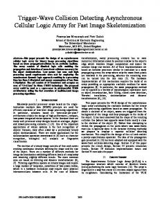
In order to cope with high luminosities and large background rates the DELPHI trigger system is composed of four succesive levels, T1, T2, T 3 and T 4 of increasing selectivity. The first two trigger levels (T1 and T2 respectively) are synchronous with respect to the Beam Cross Over (BCO) while the third and fourth (T3 and T 4 respectively) are software filters performed asynchronously with respect to the BCO [3]. At present, with four bunches of electrons and positrons circulating in the machine the LEP bunch-crossing interval is 22 ps. The trigger decisions for T1 and T2 are taken 3 and 39 ps after the BCO respectively. At a typical luminosity of 5 x lo3' cm-2s-1, normal trigger rates are of the order of 400 Hs and 4 HI for T1 and T2 respectively. T1 and T 2 have been active from the very beginning of 1989 (pilot run). In 1992 T 3 was implemented with the aim of maintaining the data logging rate below 2 He, and T4 to tag some of the background events. The timing signals necessary to start/control the trigger decision logic are generated and controlled by a set of FASTBUS modules constituting the nigger Supervisor. They are implemented locally in each detector partition and centrally in the trigger partition (see Figure 1):
-
0
in the central part, the Trigger Supervisor Decision Box (TS-DB) or PYTHIA [4], receives the subtrigger data from the different partitions and, on the basis of programmable logic, takes the trigger decision a t the
--. ._
typical background of single detector triggers. The geomo trical acceptance of the different detectors provides a good amount of redundancy between these trigger conditions. This is a major feature of the DELPHI trigger system since it ensures a stable situation for long running periods and allows a study of the trigger performance using real data only. In order to construct the final DFs a programmable logic based on a three level structure of Look-Up'Ibbles (LUT) is employed [3, 41. This makes the whole system very flexible and allows for an extremely large number of M e r e n t logical combinations. After a positive T 2 trigger decision T 3 validates the same logic configurations of T 2 but with the full detector granularity and better detector resolution. A fraction of 50% of all T2 triggers are thus rejected. For specific individual trigger components such rejection can reach values of 80-90%. T4 is intended as a real time event tagger and it is presently used only for monitoring and flagging events.
first two levels. In order to monitor these inputs to PYTHIA the signals are duplicated and sent to a set of scalers for online monitoring. The Trigger Supervisor Control Box (TS-CB), called ZEUS [5], distributes common timing signals to all the partitions and, in addition, receives the trigger decisions from PYTHIA and broadcasts them again to all the partitions. the modules are included in each individual partition or subdetector where the different control and decision subtrigger signals are synthesised. They formally operate as local versions of the modules mentioned above but with their particular detector apecifications. These modules are: the Local Trigger Supervisor Decision Box (LTS-DB) and the Local Trigger Supervisor Control Box (LTS-CB) also referred to as PANDORA [6].
-
N
PARTITION ................................................... I
:
3
UWULB
......... ........
Online Software Scheme
!
!-
3.1
I
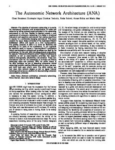
As for any other partition, a Crate Pmcessor tad (CP) provides the main data stream of DELPHI with the trigger data. In parallel the trigger FIP houses a continuously running Scaler task. It regularly reads scaler data and sends them to a VAX server over TCP/IP. It also receives LEP parameters from the VAX and makes them available to the CP task to be embedded in each event. Figure 2 shows schematically the organization of the trigger online software.
!
-: ..................................................
Figure 1: Schematic view of the interconnections between the trigger control and decision lines for the central and local units.
3.2
Control and Monitoring
The performance of the trigger system is continuously monitored in order to quickly identify any malfunction which would lead to variations in the trigger efficiencies and live time. The trigger monitoring is achieved using both streams of data described above. The event data analysis is included in the general online monitoring scheme of DELPHI [8] whereas scaler information are analyzed from dedicated global sections on the VAX (on Figure 2). The main tools used for the trigger monitoring are:
The above mentioned central trigger modules (ZEUS and PYTHIA) as well as others related to the trigger partition, are located in three FASTBUS crates close to the detector. A Fastbus Intersegment Processor (FIP) [7] acts as the crate processor controller. All the software needed to perform the tasks concerning the initialization, read-out and monitoring resides in the FIP.
2.2
Crate and Scaler tasks
Central Trigger Logic
Each partition contributes to the trigger decision with data generated by the respective subtrigger processors. A total of 86 and 95 bits (Trigger Data Lines or TDL) at T1 and T 2 respectively are sent to the central trigger processor PYTHIA. The decision of both T1 and T2 is taken by ORing a number of logic functions (Decision Functions or DF) formed out of the input bits. These DFs have the structure of majorities, a powerful way to correlate detectors in a quasi-single track or cluster configuration without the
318
i) Real time trigger monitor displays. These have been developed for fast online real time checks and provide information on individual trigger rates, scaler contents, live time, etc. The User Interface of these environments are based on the V M S 8SMG RTL package and the X-windows and OSF/MotifTM graphic tools. ii) Trigger quality checking monitor.
It provides information on the trigger data recorded into tape on a short time scale. It is implemented inside a central monitor program task together with the monitoring
Trigger Global Efficiencies
uu
UI-
Muon8 UQ-
Figure 2: Organization of the online software.
of the rest of the partitions, although a local version runs in the trigger partition. This is periii) Offline analysis of trigger efficiencies. formed after the reconstruction of the Raw Data. It is typically accomplished a few days after data taking.
Acknowledgements We would like to acknowledge all the members of the DELPHI Data Acquisition System group for their help and advise. We are also very grateful to the various detector people for their cooperation in all circumstances.
References 4
Performance of the Trigger
[I] P. Aarnio et al., The DELPHI detector at LEP. NIM AS03 (1991) 233.
The average efficiencies within the DELPHI acceptance (0’ 5 4 5 360° and 20° 5 6 5 160’) for either hadronic or leptonic final states were found to be higher than 99.9% with statistical and systematic errors below 0.01% and 0.1% respectively, even in the worst instances (see Figure 3). The trigger efficiencies show almost no variation with respect to the polar angle 6. In the case of single charged tracks, the efficiency for their detection in DEL99.9% for PHI has been calculated to be higher than particles with transverse. momenta above 1.5 GeV/c2 and in the angular range of 45O < 6 < 135’.
[2] T. Adye et al., Architecture and Performance of the DELPHI Data Acquisition and Control System. DELPHI 91-93 DAS-113. Presented at the CHEP conference at Tsukuba, March 1991. J. A. Fuster et al. The Online Software for the First and Second Level Trigger of DELPHI. DELPHI 91-112 DAS-I 15. V. Perrera, PYTHIA module A/B user guide; PYTHIA module C user guide; PYTHIA Receiver user guide. RAL internal report (1989). V. Canale and G. Valenti, PYTHIA Programming. DELPHI 92-15 DAS 122. L. Cerrito, ZEUS: The Trigger Supervisor Control Box. Writeup and User Manual, DELPHI 90-12 DAS-102. S. Cairanti et al., PANDORA: The DELPHI Local ‘higger Supervisor Control Box. User Manual. DELPHI 89-12 DAS-92. M. Mur, The Fastbus Intersegment Processor (FIP). Hardware reference manual. J. N. Albert et al., The DELPHI Hmtogram Presenter. DELPHI 92-100 DAS-129. Presented at the 1992 “Software Engineering, Artificial Intelligence and Expert Systems in High Energy and Nuclear ,Physics” at La Londe des Maures Provence, France, January 1992.
-
5
Conclusions
The DELPHI trigger system provides an efficiency nearly 100% over the covered solid angle for all particles and physical channels. The system has also proved to be stable in spite of very different beam conditions. This is a consequence of the high redundancy provided by the different detectors for all e+e-final state processes which, in addition, ensures a method to calculate the absolute trigger efficiencies using data only.
319