NASA/TM—2007-214906
Array Phase Shifters: Theory and Technology Robert R. Romanofsky Glenn Research Center, Cleveland, Ohio
October 2007
NASA STI Program . . . in Profile
Since its founding, NASA has been dedicated to the advancement of aeronautics and space science. The NASA Scientific and Technical Information (STI) program plays a key part in helping NASA maintain this important role. The NASA STI Program operates under the auspices of the Agency Chief Information Officer. It collects, organizes, provides for archiving, and disseminates NASA’s STI. The NASA STI program provides access to the NASA Aeronautics and Space Database and its public interface, the NASA Technical Reports Server, thus providing one of the largest collections of aeronautical and space science STI in the world. Results are published in both non-NASA channels and by NASA in the NASA STI Report Series, which includes the following report types: •
•
•
TECHNICAL PUBLICATION. Reports of completed research or a major significant phase of research that present the results of NASA programs and include extensive data or theoretical analysis. Includes compilations of significant scientific and technical data and information deemed to be of continuing reference value. NASA counterpart of peer-reviewed formal professional papers but has less stringent limitations on manuscript length and extent of graphic presentations. TECHNICAL MEMORANDUM. Scientific and technical findings that are preliminary or of specialized interest, e.g., quick release reports, working papers, and bibliographies that contain minimal annotation. Does not contain extensive analysis. CONTRACTOR REPORT. Scientific and technical findings by NASA-sponsored contractors and grantees.
•
CONFERENCE PUBLICATION. Collected papers from scientific and technical conferences, symposia, seminars, or other meetings sponsored or cosponsored by NASA.
•
SPECIAL PUBLICATION. Scientific, technical, or historical information from NASA programs, projects, and missions, often concerned with subjects having substantial public interest.
•
TECHNICAL TRANSLATION. Englishlanguage translations of foreign scientific and technical material pertinent to NASA’s mission.
Specialized services also include creating custom thesauri, building customized databases, organizing and publishing research results. For more information about the NASA STI program, see the following: •
Access the NASA STI program home page at http://www.sti.nasa.gov
•
E-mail your question via the Internet to
[email protected]
•
Fax your question to the NASA STI Help Desk at 301–621–0134
•
Telephone the NASA STI Help Desk at 301–621–0390
•
Write to: NASA Center for AeroSpace Information (CASI) 7115 Standard Drive Hanover, MD 21076–1320
NASA/TM—2007-214906
Array Phase Shifters: Theory and Technology Robert R. Romanofsky Glenn Research Center, Cleveland, Ohio
National Aeronautics and Space Administration Glenn Research Center Cleveland, Ohio 44135
October 2007
Level of Review: This material has been technically reviewed by technical management.
Available from NASA Center for Aerospace Information 7115 Standard Drive Hanover, MD 21076–1320
National Technical Information Service 5285 Port Royal Road Springfield, VA 22161
Available electronically at http://gltrs.grc.nasa.gov
Contents Introduction................................................................................................................................................... 1 Applications............................................................................................................................................ 1 Military Phased Array Antennas...................................................................................................... 1 Commercial Satellite Communications ........................................................................................... 2 Automated Highway Systems.......................................................................................................... 2 Phase Shifter Characteristics............................................................................................................ 3 Semiconductor .............................................................................................................................................. 3 High-Pass/Low-Pass............................................................................................................................... 3 Loaded Line ..................................................................................................................................... 4 Switched Line .................................................................................................................................. 5 Beam Squint..................................................................................................................................... 6 Digital Control ................................................................................................................................. 7 Switching Q ..................................................................................................................................... 7 Thin Film Ferroelectric ................................................................................................................................. 8 Materials and Basic Properties ............................................................................................................... 8 Coupled Microstripline .................................................................................................................... 9 Theory of Coupled-Line Type ....................................................................................................... 10 Micro-Electro-Mechanical Systems (MEMS) ............................................................................................ 11 Slow-Wave.................................................................................................................................................. 12 One-Dimensional Periodic Structures .................................................................................................. 12 Ferroelectric Varactor........................................................................................................................... 13 Ferrite.......................................................................................................................................................... 14 Microstrip Type.................................................................................................................................... 15 Superconducting Applications .................................................................................................................... 16 Effect of Phase Shifter Behavior on Phased Array Bit Error Rate.............................................................. 17 Modulo 2π Effects................................................................................................................................ 17 Phase Errors.......................................................................................................................................... 18 Effect of Finite Response Time on Beam Evolution ..................................................................... 18 Summary ..................................................................................................................................................... 20 References................................................................................................................................................... 20
NASA/TM—2007-214906
iii
Array Phase Shifters: Theory and Technology Robert R. Romanofsky National Aeronautics and Space Administration Glenn Research Center Cleveland, Ohio 44135
Introduction While there are a myriad of applications for microwave phase shifters in instrumentation and metrology, power combining, amplifier linearization, and so on, the most prevalent use is in scanning phased-array antennas. And while this market continues to be dominated by military radar and tracking platforms, many commercial applications have emerged in the past decade or so. These new and potential applications span low-Earth-orbit (LEO) communications satellite constellations and collision warning radar, an aspect of the Intelligent Vehicle Highway System or Automated Highway System. In any case, the phase shifters represent a considerable portion of the overall antenna cost, with some estimates approaching 40 percent for receive arrays. Ferrite phase shifters continue to be the workhorse in militaryphased arrays, and while there have been advances in thin film ferrite devices, the review of this device technology in the previous edition of this book is still highly relevant. This chapter will focus on three types of phase shifters that have matured in the past decade: GaAs MESFET monolithic microwave integrated circuit (MMIC), micro-electromechanical systems (MEMS), and thin film ferroelectricbased devices. A brief review of some novel devices including thin film ferrite phase shifters and superconducting switches for phase shifter applications will be provided. Finally, the effects of modulo 2π phase shift limitations, phase errors, and transient response on bit error rate degradation will be considered. Applications Military applications emphasize ground based systems for early warning radar, missile defense, and space surveillance. Most of the systems employ ferrite phase shifter technology, but several examples of GaAs MMIC based arrays exist. Space applications, including civilian space applications, include synthetic aperture radar and satellite communications. Another burgeoning commercial application is collision warning and collision avoidance radar for the Intelligent Vehicle Highway System. Military Phased Array Antennas Table 1 summarizes some of the military phased array radar systems (refs. 1 and 2). Note that many of the arrays developed during the last three decades had production runs of over 50 and that even one radar system can necessitate a very large number of phase shifters. The last two systems use MMIC modules. The Theater High Altitude Area Defense (THAAD) ground-based radar required over 60,000 MMIC phase shifter chips. The program demonstrated a per-module cost of about $1,000. The Counter Battery Radar (COBRA) artillery and mortar weaponlocating system required more than 8,000 MMIC modules.
NASA/TM—2007-214906
1
TABLE 1.—PHASED ARRAY SYSTEM EXAMPLES (Reprinted with permission from Microwave Journal, vol. 40, no. 5, May 1997, pp. 288–294) System Frequency Number Phase shifters Elements Manufacturer band manufactured per array manufactured AN/TPN-25 X 18 824 14,850 Raytheon AN/GPN-22 X 60 443 26,580 Raytheon Cobra Dane L 1 34,769 34,769 Raytheon Pave Paws UHF 4 2,667 21,416 Raytheon BMEWS UHF 2 3,584 17,920 Raytheon Cobra Judy 1 12,288 12,288 Raytheon Patriot C 173 5,000 865,000 Raytheon AEGIS/SPY-1 S 234 4,000 936,000 Raytheon B-1 X 100 1,526 152,600 Northrup AN/TPQ-37 S 102 359 36,618 Hughes Flap Lid X >100 10,000 >1 million USSR THAAD X 2.5 25,344 63,360 Raytheon COBRA C 3 2,700 8,100 Lockheed
Commercial Satellite Communications Customers for commercial satellite services include remote or mobile data-intensive professionals requiring fast downloading and uploading capabilities. Example users are banks, businesses using videoconferencing, oil drilling platforms, medical evacuation helicopters, airliners, cruise ships and the like. In developing countries, where a communications infrastructure is close to nonexistent, corporations are in need of ways and means to communicate. However, the greatest growth in demand may be fueled by consumer (residential) requirements such as: distance learning, electronic mail, home shopping, telecommuting, and entertainment services such as high definition television and video phones. Compared to geostationary (GEO) satellites, LEO satellites offer at least three major advantages. First, they orbit at an altitude generally below 1,000 km instead of about 35,000 km. Since signal loss is proportional to distance squared, an automatic power savings of about 30 dB occurs. This permits substantially smaller Earth terminals. Second, their proximity provides a nearly imperceptible propagation delay just like terrestrial systems, instead of the 0.25 second delay associated with GEO satellites. While this may be nothing more than a nuisance for voice services, it causes technical problems with higher data rates (for example, computer networking) and handshaking (for example, ATM switching). Third, there is potential for significantly reduced launch costs. For practical, aesthetic, or technical (agility and reliability) reasons, scanning phased arrays seems to be the lynchpin. System architectures tend to place considerable burden on the space segment, allowing the use of relatively small (for example, < 1 m) Earth terminals, to support data rates from perhaps 2.048 to 155.53 Mbps. These quixotic visions have yet to be realized, but could become tractable given a low-cost phased array solution. There are also high data rate GEO platforms such as Spaceway (Hughes). Mobile platforms requesting service need some type of articulated antenna to track the satellite, both because of variable latitude and longitude, and to compensate for pitch, roll, and yaw. Again, the low-cost phased array seems an elusive solution. Automated Highway Systems At the turn of the millennium, there were about 140 million automobiles just in the United States. As populations grow, highway traffic expands, but construction costs and available real-estate prevent the highway system from keeping pace. The Intelligent Vehicle Highway System, especially in the context of intelligent cruise control, collision avoidance radar, and electronic tolling is a solution to optimize traffic flow and reduce flawed decision making. For a collision warning application, the phased array can be relatively small. Preliminary specifications suggest an operating frequency of 77 GHz with a 1.5° by 6° beamwidth, a 10 Hz scan rate, and 10 mW output power (ref. 3). Electronically-steered arrays enhance collision avoidance radar both because of the beam-pointing precision requirements, and the need to NASA/TM—2007-214906
2
essentially see around corners. The specified transmitter power corresponds to a timely warning for detecting a human, with a 1 m2 radar cross-section, at a 300 m range (ref. 4). Phase Shifter Characteristics Evolving high data rate communications systems demand greater attention to subtle aspects of information theory and electromagnetic engineering. As the ratio of signaling bandwidth to carrier frequency decreases, less familiar phenomenon can influence system performance. And, new coding techniques are pushing channel capacity ever closer to the Shannon limit (ref. 5). Some interesting effects are expected to appear if the trend toward wide-band scanning phased array antennas and efficient highspeed modulators continues (ref. 6). For example, in a phased array antenna inter-element spacing, the physical size of the array, and the steering vector can conspire to introduce pulse distortion from group delay, inter-symbol interference, and beam squinting (refs. 7 and 8). And the operating point of the amplifiers can affect the bit error rate depending on the modulation type and the number of carriers. Naturally one wants the phased array to operate as efficiently as possible given power limitations and thermal management problems. This desire necessitates that the power amplifiers operate in a nonlinear region near saturation. Nonlinear effects cause amplitude-to-amplitude modulation (AM/AM) and amplitude-to-phase modulation (AM/PM) distortion. The net effect of AM/AM distortion is to alternately compress and expand the signal constellation. The net effect of AM/PM conversion is a rotation of the signal constellation (ref. 7). In a receive array, the third order intercept of the low noise amplifiers largely determines inter-modulation distortion and heat dissipation (ref. 9). But the phase shifter insertion loss envelope and phase accuracy are also key factors influencing array performance. Phase shifters typically follow low noise amplifiers in a receive array and precede power amplifiers in a transmit array. Since the phase shifter’s insertion loss depends on its phase setting and since its switching action represents some finite time domain response, its potential contribution to bit error rate degradation cannot generally be ignored. There will always be some effects in any phase-shift keyed (PSK) modulation system, the degree to which depends on the steering vector update rate and data rate. A long switching time also increases minimum radar range. Besides these issues, the satellite communication market’s desire to install tracking terminals on commercial mobile platforms, even at small office/home office and residential sites, has inspired the search for inexpensive phase shifters and affordable phased arrays. In practice, system constraints on chip size, power handling, drive power, insertion loss, bandwidth, phase error, transient response, and cost dictate particular device designs
Semiconductor Semiconductor phase shifters, based primarily on GaAs, but also on SiGe and InP, have enjoyed steady progress for the past two decades. Their small size and relatively low power consumption compared to ferrite devices has created new insertion opportunities. Many possible circuit topologies, using diode or FET switches in various configurations, exist. High-Pass/Low-Pass In principle, any variable reactance in series or shunt across a transmission line can be used to introduce phase shift. A high-pass/low-pass phase shifter π network using discrete capacitors and inductors is shown in figure 1. In the high-pass configuration shown, a relative delay is realized. In the opposite configuration, with all SPDT switches toggled, the low-pass circuit represents a relative phase advance (ref. 10). It can be shown that if the circuit is matched, X = 2B/(1 + B2) and the insertion phase is tan–1(2B/(B2 – 1)) (ref. 11). The switches can be implemented with PIN diodes or MESFETs, which will discussed later on in this section. It is possible to realize a phase shift of 180° with about 20 percent bandwidth.
NASA/TM—2007-214906
3
Loaded Line Another type of phase shifter generally used for achieving 22.5° to 45° of phase shift is the loadedline (ref. 12). A schematic of this is shown in figure 2. Ideally, reactive loads spaced one-quarter wavelength apart are shunted across a transmission line to effect phase shift. The purpose of the second shunt susceptance (jB) is to cause a reflection, which will at least partially cancel the reflection from the first shunt susceptance (jB). By equating the ABCD matrix of figure 2 to an equivalent section of transmission line with electrical length θL radians and characteristic impedance Z Ohms as given in equation (1),
⎛ 1 0⎞ ⎛ 0 ⎜⎜ ⎟⎟ ⎜⎜ ⎝ jB 1 ⎠ ⎝ j Zo
jZo ⎞ ⎟ 0 ⎟⎠
⎛ 1 0 ⎞ ⎛ cos(θ L ) ⎜⎜ ⎟⎟ = ⎜⎜ ⎝ jB 1 ⎠ ⎝ j sin (θ L ) Z
jZ sin (θ L )⎞ ⎟ cos(θ L ) ⎟⎠
(1)
we obtain
[
Z = Zo 1 − (BZo )2
]
12
(2)
and θ L = cos −1 (− BZo )
(3)
If the susceptance is capacitive, the phase velocity is decreased; if the susceptance is inductive, the phase velocity is increased. Loaded line phase shifters are inherently narrow-band and produce a constant phase shift versus frequency response. The phase versus frequency response is generally not as flat as the highpass/low-pass type.
NASA/TM—2007-214906
4
Switched Line
The switched-line phase shifter is yet another popular type, and is intuitively easy to understand. SPDT switches are used to toggle between transmission lines with different path lengths. As opposed to the types discussed previously, this one is a true time-delay device. That is, it provides a phase response (φ) proportional to frequency (ω). Since time delay, τ = –dφ/dω and φ is proportional to ω, τ is a constant over the bandwidth. A schematic is shown in figure 3. The differential phase shift is
Δϕ ≈ β(L 2 − L1)
(4)
where β is the propagation constant of the transmission line. As usual, β equals the radian frequency ω divided by vp, where vp is the phase velocity. A point of caution needs to be made with regard to this design, however. Utilizing series diode switches, it is possible that the off path length and switch capacitance can conspire to create a through path in parallel with the on path, resulting in high insertion loss and abrupt phase change in band. Utilizing MESFETs in place of the SPDT switches shown, the on path could also experience high loss under certain conditions. If the MESFET is treated as a very small resistance in series with a pinch-off capacitance of 0.1 pF, the insertion loss (and phase) of the “on” path, say L2, will vary as shown in figure 4 with L2 as a parameter.
NASA/TM—2007-214906
5
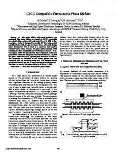
The higher loss with increasing L2 is predominantly due to interaction with the switches, not dissipative loss. So L1 and L2 must be chosen with deference to the switch characteristics. A photograph of a 4-bit GaAs monolithic phase shifter is shown in figure 5 (ref. 13). The chip size is approximately 5.5- by 2.5- by 0.15-mm3. The 180°, 90°, and 45° bits are implemented using the switched line approach, whereas the 22.5° bit is realized with a loaded line. The operating frequency was 30 GHz with about a 10 percent bandwidth. Average insertion loss was