Assembly optimised FFT algorithms for TMS320C62 processors S.Ricci, F.Guidi and P.Tortoli Electronics and Telecommunications Dept. Via S. Marta, 3 - 50139 Florence (Italy) Fax: +39 055 494569 e-mail:
[email protected]
Abstract Severe speed and dynamic range requirements are often imposed to the FFT algorithms necessary in modern communication systems. In this paper we discuss hand-optimised assembly codes for fixed-scaling and block-floatingpoint FFT algorithms providing 90% speed improvement with respect to the codes produced by TI C-development tools. Their use in a TMS320C6202-based system designed in our laboratory for range-Doppler applications is also described.
Introduction Dynamic range requirements of Fast Fourier Transform (FFT) algorithms produce elaborate codes that are not easily handled by high level compilers. Poor machine code and loss of speed performance are typically yielded. This is particularly true for the TMS320C62 DSP family. To take full advantage of the eight parallel functional units of the VelociTI architecture, TI C-development tools try to produce a particular loop optimisation called ‘software pipeline’. Unfortunately, when handling the FFT algorithm, the TI C optimiser fails in building software pipelining, and this results in a dramatic performance loss. In this paper hand-optimised assembly codes for fixed-scaling and block-floating-point Radix-4 FFTs are presented. In general, a 90% speed improvement was achieved. In particular, the block floating point code is shown capable to process a 1024 point-FFT in less than 22050 clock cycles, including all I/O operations. These codes have been used in a new system consisting of a Personal Computer (PC) board based on a 200 MHz TMS320C6202. The board includes a high-speed A/D interface, an input 32-bit wide FIFO, up to 128 Mbytes SRAM and a standard PCI interface with master capability. A software-programmable FPGA produces and accepts synchronisation pulses, making the system suitable for a wide range of applications. In particular, the block floating point algorithm is here shown appropriate for radar matched filtering, where frequency modulated signals with wide bandwidth and short length have to be processed in real time to yield output peak-to-sidelobe ratios up to 70 dB.
High level language vs hand optimised assembly The typical code development flow for ’C6x devices starts by writing down the code in C language and checking the achieved performance. When the latter is not satisfactory, some easy tips are applied to the C code and, if necessary, linear assembly is used. If adequate performance is still not achieved, the code must be modified to drive the compiler fitting for the velociTI architecture. A better ‘C6x core comprehension is of course here necessary. The ultimate speed improvement is obtained by ‘software pipeline’. This technique consists in a loop optimisation based on the parallel execution of distinct loop instances. Many reasons make this procedure difficult: complex data dependencies, nested loops, trip counter changes, function calls, conditional breaks, excessively large code, need for more than 32 registers, etc. Some of these problems may be overcome through code revisions, others may not, depending on the algorithm to be implemented.
FFT dynamic range on fixed point DSPs FFT dynamic range performance on fixed point DSPs heavily depends on the specific technique employed to prevent overflow. The simplest way to prevent overflow is feeding the FFT with a sufficiently small signal. For example, the TI FFT benchmark for ‘C62x DSP family has no procedure to control overflow. This makes the code very quick, but the input data corresponding to, e.g., a sinusoidal signal, must be limited to 9 significant bits, with a large dynamic range limitation. Fixed scaling represents a better way to avoid overflow. It involves a data division before every butterfly computation. The division factor is kept as low as possible 16 to limit the dynamic loss. For example, for the Radix-4 FFT, where a 3-bit scaling would by mathematically necessary, 2-bit scaling is typically preferred because it is sufficient in most practical cases. 16-bit The conditional scaling procedure examines the input data on every FFT stage alignment and carries out scaling only if necessary. In the block-floating-point FFT algorithm, data are aligned at a 16-bit format on every stage. In both cases, a dynamic improvement is obtained at the expense of longer computational times.
32
32-bit sums
32 32-bit sums
32 2-bit scaling
FFT implementations FFT implementation typically consists in two nested loops, the outer counting stages, the inner counting the butterflies. Many operations, like the coefficients refresh, depend on the trip counter value. Block-floating-point math yields large codes full of conditional operations, and automatic compiler optimisation fails in producing software pipeline. By proceeding with hand assembly optimisation, we implemented 2 FFT algorithms using fixed scaling and block-floating-point techniques, respectively. Both codes are in place Radix-4 FFTs, using frequency division. Radix-4 algorithm has been chosen for better speed performance in spite of its major complexity, compared to Radix-2. 16+16-bit complex samples are processed using 16 + 16-bit twiddle factors. The FFT accepts samples in natural order and produces results in digit reversed sequence. For data reordering we used the code available in the TI WEB site. A simple C interface has been written so that the hand optimised FFT codes can be called by C programs by specifying, as parameters, the data and coefficients buffers and the FFT length.
16 Block-floating-point FFT 16x16-bit mult.
32 32-bit sums
32 15-bit scaling
16 Figure 1
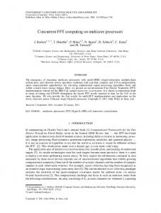
In our Block-floating-point FFT, every Radix-4 butterfly performs calculations that can be expressed by four real equations of the following form:
U =
[(I1 ± I 2 ) ± (I 3 ± I 4 )]× W1
±
[(I 5 ± I 6 ) ± (I 7 ± I8 )]× W2
where U is the real or imaginary part of any of the four complex output data, Ii are the real or imaginary parts of any of the four complex input data and Wi are the real or imaginary parts of the twiddle factors. Complex input data are stored as 16+16-bit samples in the internal DSP memory. Before every butterfly stage, they are left-shifted in such a way that at least one of them has a single sign bit. The sums within square brackets are then carried out in 32-bit registers, with no overflow possibility. The results may grow up to 18-bit and a 2-bit scaling drives the dynamics back to 16-bit, as requested by ‘C62 multipliers. Multiplications by the complex coefficients Wi are performed to get a 32-bit result with double sign bit, i.e., with an effective 31-bit register length. A 15-bit scaling follows the final 32-bit sum. This implies a theoretical overflow possibility that would be avoided by a 16-bit scaling. A dynamic range improvement is preferable to the mathematical certainty of avoiding overflow, since the latter may occur only with particular signals like, for example, complex square waves.
Speed performance The speed performance obtained by hand optimised FFT codes was evaluated by using the simulator Profiler tool. This debug software reproduces ‘C62 operations and allows to trace the algorithm flow as it is executed by the DSP. In particular, the simulator counts the needed clock cycles and some detrimental events, such as memory conflicts, may be monitored and solved. Table I shows the clock cycles needed to work out three FFT sizes. It also compares the performance achieved with C compiled and hand optimised algorithms. The latter ones guarantee a 90% improvement in all cases. For example, running 1024-point FFT on a 250 MHz ‘C62x DSP takes less than 88µs for block-floating-point, and 52µs for fixed scaling. 52µs is also the time needed by using the TI FFT benchmark, which doesn't operate any data scaling.
FFT size
Radix-4 Block Floating Point FFT
Radix-4 Fixed Scaling FFT
Hand Optimised
Automatic Optimised
Hand Optimised
Automatic Optimised
N=64
1046
11700
654
4776
N=256
4611
54027
2726
21352
N=1024
22048
260870
13054
103976
Table I: FFT clock cycles
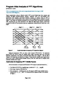
TMS320C6202-based PC board The FFT routines have been experimentally tested through a PC processing board implemented for biomedical and radar applications. The board, based on a TMS320C6202 DSP, includes two analog channels for acquisition of both components of complex input signals. Analog These components feed two 10MSPS 14Conditioning bit A/D converters. Digital samples are temporarily stored in a 32-bit wide FIFO to be read by the TMS320C6202 glueless FIFO interface through a 40 MHz bus. The same 32-bit wide bus connects the DSP to a PCI interface device with 14bit 10MSPS internal programmable DMA and master capability on the PCI bus. Up to 128 Mbytes of 100 MHz SDRAM paged in 4 banks are available, 200MHz providing a 400 Mbytes/s bandwidth. The Synchronous Signal 32 Bit 50MHz Generator (SSG) is a programmable unit 32bit Bus 32bit Bus that produces control signals such as the 40MHz 100MHz ADC clock. SSG can accept external pulses to synchronise internal events. For example, a sampling burst clock may PLX9054 be generated starting from an external occurrence. 32 bit 100MHz The TMS320C6202 has been preferred to the ‘6201 because of its capability of managing two independent PC 32-bit wide buses with synchronous operations. Multiple DSP boards could work in parallel by using the PC RAM as Figure 2: TMS302C6202 board an expansion buffer.
SSG
ADC
TMS 320C6202
FIFO
PCI
SDRAM
Dynamic range test The dynamic range of an FFT algorithm in most cases depends on the input signal features. If coherent sinusoidal test signals are used, the Spurious Free Dynamic Range (SFDR), a parameter typically employed in the characterisation of AD converters, can be considered. In our case, fixed scaling and block floating point algorithms produce 69dB and 79dB SFDRs, respectively. A more thorough test was represented by application in frequency domain matched filtering of wideband signals. Here, the input waveform is Fourier transformed, its spectrum is multiplied by a pre-calculated conjugate spectrum, and the product is transformed back into the time domain. Two FFT steps are thus involved. When input FM (chirp) waveforms are used, as in radar systems, the output signal typically turns out to be a narrow pulse with low sidelobes (compressed pulse). A high dynamic range is therefore requested. A 50 µs-length, 2 MHz-bandwidth non linear chirp signal has been processed using both block floating point and fixed scaling FFT to produce the compressed pulses shown in Figure 3. While the use of block floating point FFT produces a compressed pulse nearly equivalent to the theoretical one, with a peak-to-sidelobe ratio up to 70 dB, the fixed scaling FFT yields a 20dB dynamic range loss.
Fixed scaling pulse
Block Floating Point pulse Figure 3
Conclusions Fixed scaling and block floating point FFT algorithms have been developed in hand optimised assembly language for ‘C62x VelociTI architecture. In particular, the latter algorithm has been shown capable of speed performance compatible to the TI FFT benchmark. Experimental tests in a specially designed PC board have shown that the block-floating-point algorithm is suitable for sophisticated applications such as matched filtering of wideband FM waveforms.
Acknowledgements Valuable help by Maurizio Baldanzi, Barbara Martini and Fabio Sonnati is gratefully acknowledged. Special thanks go to Massimo Martelli (TI, Italy) for his friendly and qualified assistance within the frame of the Elìte program.
Authors Profile Stefano Ricci was born in Prato, Italy, in 1970. He received the Laurea degree in 1997 from the University of Florence. He joined the Electronic Engineering Department at the University of Florence as PhD student in 1998. His research interests are on high performance DSPs and digital circuits design. Francesco Guidi was born in Florence, Italy, in 1964. He was graduated in electronics by technical high school in 1984. Since 1991, he was been with the Department of Electronic Engineering of the University of Florence, where he is mainly engaged in research on ultrasound Doppler techniques. Piero Tortoli received the Laurea degree in Electronic Engineering from the University of Florence in 1978. Since then he is with the Electronic Engineering Department of the University of Florence, where he is presently professor of Electronics. His main interests are in the area of signal processing systems and devices with application to biomedical instrumentation and radar.


![[PDF] Download Assembly Language for x86 Processors - Google Sites](https://m.moam.info/img/260x300/pdf-download-assembly-language-for-x86-processors-_64783263097c47a9708c8f0e.jpg)
![[PDF] Assembly Language for x86 Processors (7th ... - Google Sites](https://m.moam.info/img/260x300/pdf-assembly-language-for-x86-processors-7th-googl_6477d1bb097c474d228c76be.jpg)
![[PDF] Download Assembly Language for x86 Processors - Google Sites](https://m.moam.info/img/260x300/pdf-download-assembly-language-for-x86-processors-_6477e626097c474b228c974f.jpg)
![[PDF] Download Assembly Language for x86 Processors - Google Sites](https://m.moam.info/img/260x300/pdf-download-assembly-language-for-x86-processors-_6477f065097c47a9708c459d.jpg)


![[PDF] Download Assembly Language for x86 Processors - Google Sites](https://m.moam.info/img/260x300/pdf-download-assembly-language-for-x86-processors-_6477b713097c4786708c046c.jpg)

