LiDAR; laser scanning; point cloud; airport surveillance; apron control; apron ..... injected by a jet engine during taxiing on the apron might lead to an engine ...
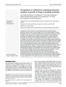
Performance Evaluation of LiDAR Point Clouds towards Automated FOD Detection on Airport Aprons Johannes Mund1, Alexander Zouhar1, Lothar Meyer2, Hartmut Fricke2 and Carsten Rother1 1
Technische Universität Dresden Dresden, Germany
{johannes.mund, alexander.zouhar, carsten.rother}@tu-dresden.de 2 {meyer, fricke}@ifl.tu-dresden.de
ABSTRACT Both the current system of airport ground control and the continuous implementation efforts of A-SMGCS and Remote Tower concepts require complete and independent surveillance coverage in real-time. We believe that 3D point clouds generated by an actively scanning LiDAR system available at TU Dresden may satisfy these high standards. Nonetheless, the utilization of LiDAR sensing for airport ground surveillance purposes is extremely challenging due to the unique requirement profile in this domain. This is also the reason why existing solutions in other domains such as autonomous driving and robotics are not directly applicable for airport ground surveillance. In a first step, we developed point cloud object detection and segmentation techniques to present that new data comprehensively to the airport apron controller. In this paper, we focused on the timely detection of dislocated objects (foreign object debris, forgotten equipment etc.) as a serious cause to hazardous situations on airport movement areas. The results are promising for various reference targets. However, the detection of very small objects (e.g. socket wrench) requires more elaborate algorithms to take full advantage of the current LiDAR technology. In the future we will assess the strength of LiDAR-based surveillance in terms of the number of hazardous situations that could be avoided or safely managed by the apron controller.
Categories and Subject Descriptors • Applied Computing~Physical sciences and engineering~Aerospace • Computing methodologies~ Computer vision~ Computer vision problems~Object detection
Keywords LiDAR; laser scanning; point cloud; airport surveillance; apron control; apron management service; object detection; foreign object debris; FOD
1. INTRODUCTION In our concept studies in [1] and [2] we clearly explained why airport ground operations, in particular those on the apron area, are regarded as significant risk drivers in the aviation sector. The apron, which can be characterized as an unstructured working environment with a large variety of objects, is a major contributor to this risk situation. Numerous activities of moving aircraft (AC), vehicles, equipment and personnel are additional factors that make the apron a complex and dynamic system [3] [4], causing even severe incidents and accidents [5] [6]. Except for the runway [7], the apron is to be considered as one of the most hazardous working environments at the airport. At the same time, almost all stakeholders operating on the apron rely on the see-and-avoid principle, which in turn is primarily Permission to make digital or hard copies of all or part of this work for personal or classroom use is granted without fee provided that copies are not made or distributed for profit or commercial advantage and that copies bear this notice and the full citation on the first page. To copy otherwise, or republish, to post on servers or to redistribute to lists, requires prior specific permission and/or a fee. ATACCS’15, September 30– October 2, 2015, Toulouse, France. Copyright 2015 ACM 978-1-4503-3562-1 …$15.00.
based on the direct view. Typical limitations of this principle are the sensitivity against view-restricting weather and lighting conditions, its dependency on the line-of-sight, and resolution limitations of the human eye. Even looked-but-failed-to-seeerrors [8] can be potentially related to this principle. In addition to the direct view, also supporting ground radar (X and Ku-band) and video cameras are subject to physical limitations that do not allow for permanent and overall apron surveillance. An exemplary, yet important problem is the timely detection1 of foreign object debris (FOD) on the airport`s surfaces, which could not be solved until today. The large number of conventional surveillance equipment deployed at today’s airports demonstrates that other alternative systems (e.g. millimeter wave Radar (W-band) and infrared sensors) have not succeeded in establishing themselves. Taking into account the apron`s characteristics and the limitations in the current surveillance capabilities, an information deficit resulting from a discrepancy between the information demand and the information available can be attested. As apron control is the overall authority to create and maintain operational safety, a reduced situational picture on the part of this operator most likely contributes significantly to the current risk situation on the apron. At the same time, this central role makes the apron control the most promising starting point for new approaches to risk mitigation (refer to [2]). Here we derive our research`s objective, which is motivated by improving the safety level of apron operations beyond current targets, e.g. the ICAO Advanced Surface Movement Guidance and Control Systems-Concept`s (A-SMGCS) target level of safety [9]. To mitigate the risk of incidents and accidents our approach foresees to improve the situational picture of tomorrow’s apron control through the provision of sensor data input that is new to the sector of airport ground surveillance. To identify an appropriate sensing technology we performed a review on established sensors in other domains than aviation (refer to [2]). The review focused on domains that, firstly, call for automated object detection, -classification and -tracking and, secondly, that are established in unstructured and dynamic environments (e.g. autonomous driving, robotics, defense). Here, especially the domain of autonomous driving was found to fulfill these conditions to a large extent. We learned that this progress was significantly bolstered by the utilization of 3D point clouds generated through LiDAR sensing. LiDAR, which stands for Light Detection and Ranging, is a non-cooperative Laser beam-based method to measure distances between the sensor and any reflecting object. 1 According to Johnson [45] detection is about perceiving the “presence of an object”. We would like to thank the DFG (German Research Foundation) most sincerely for funding the research presented in this paper (FR 2440/4-1).
The capabilities of LiDAR-based real-time perception in operation were successfully demonstrated in the DARPA Urban Challenge (2007) and the Civilian European Land Robot Trial (2007) [10]. At both events conventional vehicles had been equipped with a Velodyne HDL-64E LiDAR - a sensor that is characterized by its 360° horizontal field-of-view (FOV) and its capability to provide 3D point data in real-time. In the research project “Stadpilot” a Volkswagen Passat, which had been equipped with LiDAR and radar sensors, became one of the first vehicles to drive autonomously on real city roads with real traffic (e.g. described in [11]). To summarize, LiDAR combined with other sensors like video, infrared and/or radar have become a backbone for research and operationalization in the field of autonomous driving. Comparability of the autonomous driving domain with airport surface operations exists, as explained earlier. Despite these similarities, the scope of research and development of these two domains is much different. In autonomous driving, the main focus is on methods that process point cloud data along with multiple other sensor inputs, with the objective, to provide these data in a converted, machine-readable format to an automat acting as an end user (e.g. target tracking at robot cars [12], sensor fusion in [13]). In the context of aviation, real-time data processing is a major challenge, too. However, we also have to spend considerable efforts on the way the point data may be presented to a human operator2. This in turn requires taking existent ATM regulations and procedures as well as current surveillance concepts and deployed technologies related to apron surface surveillance into account. Another difference to the autonomous driving domain: A safety-effective apron surveillance capability will require a detection and classification functionality for even very small objects in a significantly larger coverage area. For the reasons given about, we chose LiDAR-generated sets of three dimensional (3D) data points (so called point clouds) to be provided at the apron controller working position (CWP). LiDAR sensing is characterized by its wavelength spectrum from ultraviolet to near-infrared (≈400nm to ≈3000nm) and the resulting extraordinarily high frequencies reaching into petahertz range3. For comparison purposes: Common primary radar uses lower frequencies in the gigahertz range. As a result, radar has a longer range than LiDAR, but suffers from target-splitting effects, poor coverage and low resolution [14] [15] [16]. The following description therefore summarizes the expected advantages of LiDAR sensing over other established airport surveillance technologies, in particular video camera, primary surveillance radar (PSR), secondary surveillance radar (SSR) and multi-lateration systems (MLAT). The advantages listed below arise from both the properties of the laser beam and constructionrelated factors of the sensor:
2
A non-cooperative measurement principle ensuring independence from a target`s active response signal (compared to SSR, MLAT etc.): As such, even noncooperative objects (e.g. FOD or apron personnel) can be detected. Furthermore, this concept is compliant to the SESAR Air Traffic Management (ATM) Target Concept D3
TU Dresden is currently developing concepts for a point cloud-based visual human-machine interface for the apron control unit carried out with the chair of Engineering Psychology and Applied Cognition and apron controllers from Dresden airport. 3 The sensor available at TU Dresden (OPAL 360 series) uses a wavelength of 1540nm.
[17], which calls for the utilization of non-cooperative sensors to enhance the operator`s situational picture.
Capability to derive the depth “z” of an object: This considerably supports the extraction progress of 3D objects from the data [18]. Video cameras or infrared cannot generate information about scene depth, whereas PSR only measures the slant range.
High pulse repetition rate (PRR) and high pulse intensities result in good temporal and spatial resolution compared to common PSR, and even high-resolution millimeter wave radar: This is most beneficial for the extraction of geometric features from raw data [19], e.g. spatial dimensions, positions.
Reduced sensitivity against adverse visual conditions compared to the human eye and standard video camera [20].
The above characteristics will help to technically realize our research approach: To develop and implement a point cloud-based surveillance concept that is capable to recognize (emerging) hazardous situations by their typical patterns (pattern recognition). Supported by post-processed point cloud data visualized on an additional screen to the controller, he should be enabled to take corrective actions in time to avoid or manage hazardous situations. Figure 1 depicts the proposed surveillance concept along with a default apron CWP. The fusion of 3D point data with sensor input from the existing means of surveillance (radar, video) will be considered at a later stage of the research (for details refer to [2]). Video
Out-the-window view
Processing Detection Classification Tracking
Visualisation
Apron controller
Figure 1. Components and key functions of the point cloudbased surveillance concept for apron control It is well understood that the described pattern recognition builds on the core capability to effectively and reliably detecting physical objects. By proposing a LiDAR point-based object detection technique and by demonstrating its technical feasibility in this paper, we not only create a solid basis for higher-level functions, but also contribute to the yet unsolved issue of detecting dislocated objects on airport surfaces, better known as FOD. In section 2, the methodological framework for the underlying risk mitigation approach, essentially a risk assessment (RA), is briefly explained, using Dresden airport (DRS) as a reference example. This will be followed by a discussion on the specific need for detecting physical objects, and in particular FOD, on airport surfaces. In a two-step approach, section 3 provides insight into object detection by LiDAR 3D points both on an algorithmic and a physical-technical level. In the following subsections, metrics for evaluating object detection performance will be derived. In preparation of a field trial to determine detectability and time to detection using LiDAR-technology, an experimental design is set up in section 4. Whereas section 5 presents the respective results, section 6 will discuss them in terms of potential contributions for safer apron operations in ATM.
2. BACKGROUND In section 1, we explained our motivation to increase the safety level of apron operations. In this section, the methodological background to the underlying risk mitigation approach will be laid down briefly. In this regard, an overview on our currently ongoing risk assessment (RA) will be provided. The RA shall deliver functional requirements for a safety-effective provision of LiDAR point cloud data to the apron controller. The functionality of object detection will be put into this context, and will then be further explained on the example of detecting FOD.
2.1 Overarching Risk Assessment In our concept study [2] we identified a discrepancy between the operator´s information demand and the information provision available at the CWP as a main reason for the current risk situation on aprons. Our risk mitigation approach foresees to fight the resulting information deficit by providing point cloud data to the apron controller. This new information shall be presented on an additional screen at the CWP. The development of such a “sociotechnical system” (e.g. defined by Hollnagel [21]) normally follows functional- and non-functional requirements4. The group of functional requirements will be considered as concrete countermeasures to the identified information deficit, determining quality, quantity, and time of provision of point cloud data at the CWP. The overall causal relationship is depicted in Figure 2: Determination of Information Deficit (Hazard & Cause Analysis)
Development of Countermeasures
Functional Requirements for Point Cloud Provision
Figure 2. Causal chain for deriving functional requirements The definite determination of the information deficit is crucially important for the success of the approach. To do so, we performed a hazard and cause analysis as part of a RA5. This involved the analysis of all surveillance related tasks and processes of the apron control at Dresden airport (including the information demand), as well as the collection of all information sources available at the CWP (information provision). To gain insights about the information deficit, hazards that can be attributed to an unbalanced relation between information provision and demand were identified, followed by the determination of possible consequences and probable causes. We defined a hazard as follows: “An insufficient information acquisition on the part of the controller in a specific situation demanding for specific information to safely execute the control and surveillance task of the apron control” Two main failure modes with a potentially negative impact on the controller`s situational picture were specified:
total or partial absence of demanded information
cognition of defective information
The failure modes were considered within multiple brainstorming sessions with experts from Dresden airport (apron controllers, 4
Non-functional requirements are often further differentiated into qualitative (safety requirements, ergonomic requirements etc.) and quantitative requirements (e.g. performance requirements etc.). 5 The Functional Hazard Assessment (FHA) of Eurocontrol Safety Assessment Methodology (SAM) [46] served as a methodical framework.
airport safety manager) to build the hazard list. Even hazards from completed safety assessments were reviewed and added to the list if and where appropriate (e.g. a subproject to innovativer Flughafen, iPort [22]). Upon completion, the list contains 44 hazards. As the detection functionality is in the scope of this paper, we analyzed the individual hazards regarding their potential relationship to the presence of physical objects. The following initial observation was made: 35 of 44 hazards (≈80%) are substantially related to the presence of at least one physical object / solid target (e.g. A/C, ground vehicle, FOD, guidance lines etc.). As such, we have an indication about the importance of a fully functional detection capability for solid targets. This finding is independent from to be developed specific measures to fight each of the identified hazards (not discussed in this paper). The effectiveness of our risk mitigation approach will be evaluated at a later stage of our research. This will involve human-in-the-loop simulations with real apron controllers and a limited in-the-field validation at Dresden airport.
2.2 Risk of Undetected FOD In the scope of the ongoing RA, we will investigate the capability of the proposed LiDAR system to address an exemplary, but nevertheless important hazard. We identified the undetected presence of dislocated objects on airport surfaces as serious, empirically proven safety issue for the ATM domain that has not yet been solved satisfactorily. Consequently, the resulting hazard can be found in our hazard list (refer to section 2.1), namely: “Physical Presence of FOD not perceived”. The Federal Aviation Administration (FAA) defines FOD as [23] “Any object, live or not, located in an inappropriate location in the airport environment that has the capacity to injure airport or air carrier personnel and damage aircraft”. According to Eurocontrol [24], the physical features of FOD are of typical dimensions equal to or less than approx. 6 cm2 and dark colour in more than 50% of all cases. Multiple FOD-related incidents and accidents show that both severity and probability of occurrence of FOD events are eminent enough to pose a significant risk for airport surface operations worldwide. The best known example of an FOD accident is the Concorde crash in 2000 near Paris, France with 113 casualties [25]. An Australian statistic [5] points out that five of 41 recorded ground occurrences at airports in Australia could be attributed to FOD. According to the National Aerospace FOD Prevention, Inc. [26] damage by FOD causes US$4 billion a year. The consulting group Insight SRI states that even this amount could be undervalued [27]. In addition SRI analyzed that 207 of 287 incidents per million flight operations occur due to the presence of FOD on the runway. Apart from the preferred solution to prevent the presence of FOD at all, the need to quickly and reliably detect FOD once they occurred is set forth by ICAO [28]: “The surfaces of all movement areas including pavement shall be inspected […] with the objective of avoiding and eliminating any loose objects/debris that might cause damage to aircraft or impair the operation of aircraft systems.” However, the few existing FOD detection systems, e.g. the QinetiQ's Tarsier system [29], are exclusively designed for runway inspections, and have been deployed rarely to airports so far. By proposing FOD detection from a single LiDAR source as one of many issues that are dealt with in our ongoing RA, we take a new technological approach to address this relevant safety issue.
2.3 Risk Contribution of Controller`s Inadequate Situational Awareness
3.1 Techniques for Object Detection
As explained in section 1, we see the apron controller as most promising starting point for risk mitigation, assuming that the postprocessed point cloud data will enhance his situational awareness. An (apron) controller`s activities are generally based on two main factors: Task definition and situational awareness. The first component is fixed by the manual operations, whereas the latter is the actual intended addressee in our approach. Endsley [30] defines situational awareness as “perception of the elements in the environment within a volume of time and space, the comprehension of their meaning and the projection of their status in the near future”. By visually forwarding information on detected objects to an human operator, the first level of Endsley`s model of situation awareness [31] is addressed: Perceiving“[…] the status, attributes, and dynamics of relevant elements in the environment” (see Figure 3). Situational Awareness Level 1 „Perceiving the status, attributes, and dynamics of relevant elements in the environment“
Level 2
Level 3
Figure 3. Endsley`s model of situational awareness [31]
In this section we explain our approach to detecting and segmenting objects in LiDAR-based 3D point cloud scans. The traditional problem addressed by object detection and segmentation is to find objects of known types in images and to separate them from the background. State of the art methods in computer vision often cast such tasks as labeling problem where we are given an image and need to predict labels. In this work we focus on the detection and segmentation of static objects in 3D point clouds where we assume that the objects of interest tend to be small compared to the rest of the scene. This complies with a typical FOD scenario where small dislocated objects can cause hazardous situations. Given a 3D point cloud scan of an apron scene the task is to assign each point a label (class membership), i.e., either foreground (fg) or background (bg). The task poses at least three challenges. Firstly, a typical apron scene is a highly congested environment with many different types of objects (e.g. FOD, vehicles, aircraft) and where bg-structures act as distractors. Secondly, objects can be occluded or may constitute so called “unseen-before object types”. From this it follows that the notion of what constitutes an object must be general enough in order to yield segmentations of sufficient quality. Thirdly, we do not have labeled objects at our disposal. This poses a limitation on the set of available methods suitable for this task.
This is why, level 1 is essential for generating the controller`s situational picture. This level has a high impact on safety, as missing or incorrect information can potentially result in a reduced surveillance capability or, even worse, in wrong decisions. Niessen and Eyferth [4], who adopted Endsley`s model to the ATC domain, consequently assigned level 1 to the monitoring cycle (building up the controller`s mental image and keeping it up to date). Jones and Endsley [32] analyzed the Aviation Safety Reporting System (ASRS) in terms of potential failures in the controller`s situational awareness and proofed level 1 as most important in terms of situational awareness: 72.4% of all safety-critical events that occurred in the aviation sector were found to be level 1 failures („Fail to perceive information or misperception of information“), whereas 20% of these events could be attributed to level 2 (“Comprehension of current situation”) and 4% to level 3 failures (“Projection of future states”). Regarding these numbers, our approach to improve the controller`s level 1 situational awareness by providing an independent detection functionality is confirmed6.
Figure 4. Example 3D point cloud scan representing an apron field In the present task we are given time stamped position data in 3D Cartesian format (x, y, z) where the point clouds to be processed tend to be dense and large. A typical apron scan, for example, contains about 40 million points (see Figure 4). Moreover, we have a baseline 3D scan of an apron scene at our disposal. Such a scan contains surfaces which we assume to be fixed static elements of the scene (e.g., buildings, light poles).
3. DETECTION METHODOLOGY In accordance to the findings of section 2, we aim at demonstrating technical feasibility of LiDAR point cloud-based ground surveillance for detecting physical objects, in particular FOD, on the apron. This section gives an insight into object detection from LiDAR data on an algorithmic level, followed by short background information regarding physical and technical aspects of 3D point generation at signal level. In preparation of the field trial in section 4, we will also derive metrics for evaluating the object detection performance of the proposed LiDAR system.
6
At a later stage, it is foreseen to bolster Endsley`s [42] level 2 and level 3 situational awareness. However, as both level 2 and 3 go far beyond the detection of objects, they are not considered any further in this paper.
Figure 5. Overview of the detection and segmentation schema Figure 5 depicts our proposed detection and segmentation schema. The algorithm takes as input a 3D point cloud P representing an apron scene (Figure 4) together with a bg scan Q and creates as output a segmentation and labeling S (Figure 7), where each point p ∈ P is associated with a segment, and every segment has a label (fg/bg). In order to validate the performance of the algorithm the target point cloud P contains six test objects which were placed on the apron field prior to scanning, namely the objects A through F (refer to section 4 for a detailed description). We now describe the two steps in detail.
reasonable setting. Note, that equation (1) affords a global solution using graph-cuts for which we employ the method in [34]. In Figure 7 we show a zoomed in view of the section in P where the test objects are located. On a standard PC the fg-bg segmentation (second block in Figure 5) runs about 40s so that the total run time amounts to approx. 70s. In the above example point cloud 𝑃, our current algorithm was able to find 4 of 6 test objects, namely the objects A, B, D, E (refer to section 5 for a detailed description).
3.2 Performance Metric from Signal Theory Figure 6. Distance mapping: Shown is the section of 𝑷 where the test objects A-F are located. The color mapping encodes the Euclidian distance of each point in 𝑷 to the closest point in the baseline scan 𝑸 ranging from small (blue) to large distances (red). Larger distances indicate potential object candidates. Since objects inserted in the scene are likely to rise above their surroundings a reasonable approach to finding object candidates in 𝑃 is to compute the Euclidian distance of a point p ∈ P to the closest point q in the baseline scan Q. To cope with the large amount of data we use occupancy grids known from robotic mapping to identify object candidates (see e.g. [33]) and k -d trees for fast nearest neighbor searches. On a standard PC the runtime for the extraction of geometric features (first block in Figure 5) amounts to 30s where |Q|~90 million and |P|~40 million.
The fundamental basis for the application of the above algorithm (see section 3.1) is the availability of a minimum number of 3D points of each target object, so that detection/segmentation can be realized. On a physical-technical level a 3D “echo” is generated when a signal pulse sent out by the sensor is sufficiently reflected at a target`s surface, and then transmitted back with a certain reception power 𝑃𝑅 above a predefined threshold. When adapting the LiDAR equations from Wandinger [35] and Measures [36] to the detection of solid targets using a monostatic LiDAR 7 and assuming the effective target area to be orthogonal to the laser beam, the following model equation for calculating 𝑃𝑅_ℎ𝑎𝑟𝑑 𝑡𝑎𝑟𝑔𝑒𝑡 as a function of the laser`s wavelength 𝜆 and the distance 𝑥 between sensor and target give rise to: 𝑐∆𝑡 𝑃𝑅_ℎ𝑎𝑟𝑑 𝑡𝑎𝑟𝑔𝑒𝑡 (𝑥, 𝜆) = 𝑃0 × ( ) × 𝐴𝑅 × … 2 …× 𝜇 ×
𝜌 𝜋 𝑥2
𝑥
× exp(−2 ∫0 𝛼(𝑟, 𝜆))𝑑𝑟
(2)
From this equation the following can be concluded: 𝑃𝑅_ℎ𝑎𝑟𝑑 𝑡𝑎𝑟𝑔𝑒𝑡 is internally affected by the sensor parameters transmission power 𝑃0 , the size 𝐴𝑅 of the receiver optics, the pulse length represented by 𝑐∆𝑡, and the sensor specific efficiency factor 𝜇. External factors on 𝑃𝑅_ℎ𝑎𝑟𝑑 𝑡𝑎𝑟𝑔𝑒𝑡 are: The target reflection coefficient 𝜌8, and the atmospheric transmission represented by the term 𝑥 exp(−2 ∫0 𝛼(𝑟, 𝜆))𝑑𝑟 , where 𝛼(𝑟, 𝜆)) is the extinction coefficient9. Figure 7. Foreground-background segmentation of the target point cloud 𝑷 where red denotes foreground and blue denotes background. From left to right the detected and segmented objects are: A, B, D, E. The fg-bg segmentation task may be formulated in terms of energy minimization. Let L = {0,1} denote a set of labels where 0 means bg and 1 means fg. Moreover we define the Euclidian distance of a point pi ∈ P, i ≤ |P| from the closest baseline point q ∈ Q as local feature fi ≥ 0. The task is to find a labeling S: P → L which assigns every point pi ∈ P a label si ∈ L by relating the observed features F to the labels in a spatially coherent way, i.e., the labels fi , fj of nearby points pi , pj ∈ P are more likely to agree. The formal task is then to find a labeling 𝑆 that minimizes an energy function E(S), i.e.,
From equation (2) we may draw the conclusion that the quantity 𝑃𝑅_ℎ𝑎𝑟𝑑 𝑡𝑎𝑟𝑔𝑒𝑡 mainly depends on the distance 𝑥 between the sensor and a hard target. This assumption is based on the inverse proportionality between 𝑃𝑅_ℎ𝑎𝑟𝑑 𝑡𝑎𝑟𝑔𝑒𝑡 and the squared distance 𝑥. Reducing 𝑃𝑅ℎ𝑎𝑟𝑑 𝑡𝑎𝑟𝑔𝑒𝑡 also means reducing the probability of receiving a reflection signal, which, as a result, cannot serve as input for the detection/segmentation algorithm. On the basis of these conclusions, we will regard object detectability over distance 𝑥 as a meaningful metric to evaluate the technical feasibility of the proposed LiDAR system for point-based object detection.
𝐸(𝑆) = ∑ 𝜆1 𝑓𝑖 + ∑ 𝑥𝑖 (1 − 𝑓𝑖 ) + ⋯ 𝑖
𝑖
… + ∑𝑖𝑗∈ 𝑁𝑖 𝑤𝑖𝑗 𝛿(𝑓𝑖 , 𝑓𝑗 ) → min𝑆 ,
(1)
where 𝑤𝑖𝑗 = λ2 /||pi − pj ||2 , δ(si , sj ) denotes the Kronecker-delta function and Ni contains the k −nearest neighbors of pi in 𝑃 where the parameters λ1 , λ2 ≥ 0 need to be estimated from training data. In our experiments we found k = 10, λ1 = 0.05, λ2 = 0.005 to be a
7
The Laser emitter and receiver parts form one constructional unit (e.g. Neptec OPAL series) 8 Influenced by angle of incident, surface material, laser wave length 9 A measure for the attenuation of an electromagnetic wave passing through a medium, caused by absorption and scattering
3.3 Performance Metric from the Risk Mitigation Perspective
4. EXPERIMENTAL DESIGN 4.1 Methods of Analysis
In the scope of the ongoing RA, we introduced the hazard “Physical Presence of FOD not perceived” as a relevant candidate to be addressed by the proposed LiDAR system (see section 2).
Based on the findings of section 3, a field trial will study the following dependent variables over various distances between the sensor and different target objects: Detectability and Time to Detection (TTD). The detectability measurements shall deliver universal statements on the combined performance 10 of both the sensor and the algorithm to detect different static objects. The target objects are divided into standardized objects and real objects. The use of standardized objects will allow us to keep target-related influential factors of equation (2) constant (see subsection 4.3 for details). In a subsequent step, the TTD to each successful detection shall be calculated. Here, the main goal is to derive a reference graph of detection times for the standardized objects as a function of distance. Further, the detection times of real objects (e.g. FOD) shall be compared with the reference graph.
Accidents like the Concorde crash in 2000 emphasize the need for a quick detection of FOD. In this example, a small titanium strip was lost by another aircraft and indirectly caused the Concord to crash five minutes later [25]. Even though this worst case FOD accident took place on the runway, it is reasonable to transfer the overall context to apron operations. For instance, an FOD that is injected by a jet engine during taxiing on the apron might lead to an engine failure in a more critical phase. As any specifications/recommendations regarding minimum detection times for specific FOD types were not yet defined, the rule of thumb shall be “the sooner, the better”. The currently ongoing RA (section 2.1) will deliver precise requirements regarding minimum detection times for various objects.
4.2 Experimental Environment
For the reasons given about, we introduce a second metric relevant for detecting objects, and especially FOD, namely the required Time to Detection (TTD) per object. We define TTD as the time span between the physical appearance of an object and its detection by the respective algorithm. Additional times for visualizing the data on a screen at the CWP, and times for perceiving and interpreting this information by the human operator are excluded from this definition.
A part of the apron of Dresden airport served as experimental environment. The different object positions were determined depending on the systematic variation of the distances between the sensor and the target objects. Prior to the field trial, the LiDAR sensor had been mounted on the terminal building`s roof in a total height of approx. 15m (see Figure 8). To gain the greatest possible coverage regarding relevant ground activities and to reduce shadowing, an analytical-geometric model developed at TU Dresden [37] was taken into consideration when selecting a suitable sensor position.
With our system, the TTD is composed of two parts: The time available for acquiring reflection points (acquisition time) and the computing times of the object detection/segmentation algorithm. While the latter will become comparably low with continuing development in foreseeable future (target time: