AUTOMATED 3D DATA COLLECTION (A3DDC) FOR 3D BUILDING INFORMATION MODELING F. Bosche
Carl T. Haas
PhD Candidate University of Waterloo, Department of Civil and Environmental Engineering 200 University avenue West, N2L 2X2, Waterloo, ON, Canada E-mail:
[email protected]
Professor and Director of the Center for Pavement and Transportation Technology (CPATT) University of Waterloo, Department of Civil and Environmental Engineering 200 University avenue West, N2L 2X2, Waterloo, ON, Canada E-mail:
[email protected]
ABSTRACT The Architectural/Engineering/Construction (AEC) industry is slowly shifting toward performance-driven project and project delivery. Assuring good performance requires efficient performance control processes. Among the different construction performance control processes, many critical ones, including progress tracking, productivity tracking and dimensional quality control, rely on efficient three-dimensional (3D) information flows. However, the AEC industry currently lacks reliable and efficient means of monitoring 3D information at the object level, which is critical to these processes. The authors have developed an innovative approach for automated 3D data collection (A3dDC) by automatically recognizing 3D Computer-Aided Design (CAD) model objects in 3D laser scans. This paper rapidly presents this approach and then details how it enables (1) automated life-cycle project 3D data collection for integration within Building Information Models, and consequently (2) the monitoring processes above to perform better. It is also shown how this approach enables planning for 3D scanning and ultimately strategic scanning. KEYWORDS Project Control Processes, Monitoring, Three-dimensional, Automated Data Collection (ADC), Building Information Model (BIM).
1.
points by, for instance, consuming less energy, providing good lighting conditions to the users, enabling safe and rapid evacuation in case of emergency. And, the delivery of the project must perform better from the owner and contractor’s view points (e.g. construction safety, time, quality, cost).
BACKGROUND
The Architectural/Engineering/Construction (AEC) industry is slowly shifting toward performancedriven projects and project delivery. Projects must perform better from the owner and users’ view
279
Assuring good performance requires efficient performance control processes. This is true for projects managed in a traditional manner, and even more particularly for projects using the Lean Construction management approach [1].
2. ADC-ENABLING TECHNOLOGIES AND CURRENT RESEARCH New technologies that can enable ADC include: • Global Navigation Satellite Systems (GNSSs): GNSSs include the Global Positioning System (GPS), the GLONASS system, and soon the Galileo and other systems. They allow the tracking of the three-dimensional positions of objects in the geocentric coordinate frame. The geo-positioning is achieved with different levels of accuracies depending on whether base stations and/or post-processing techniques are used or not. Note that GNSS systems do not directly provide orientation information. For this, digital compasses may be used.
Control processes include (1) a forward information flow to drive process behavior and (2) a feedback information flow for monitoring purposes [2]. The feedback flow is typically used to adjust the forward information flow in order to meet the overall expected project performance. In the AEC industry, the forward information flow corresponds to the flow of information resulting from design, planning and management activities, and the feedback flow results from construction monitoring activities.
Radio Frequency and Identification (RFID) or Ultra Wide Band (UWB) systems: RFID and UWB systems allow storing and remotely (and without line of sight) retrieving data stored in tags attached to tracked items. Indoor UWB systems are now being used like GNSS systems for precise 3D tracking inside structures.
The current state of the AEC industry is that control processes are inefficient [2, 3, 4]. In order to improve this situation, significant research efforts are currently directed toward the development of database systems that aim at rationalizing, streamlining and relating the information pertaining to a given project acquired during its entire lifecycle: from planning to construction to operation and maintenance to decommissioning. They improve the “visualization” of the project status to the user (management) and potentially enable automated project performance control. These systems are referred to as Building Information Models (BIMs), Bridge Information Models (BrIMs), City Information Models (CIMs), etc. In this paper, we will refer to these systems as Project Information Models (PIMs).
Video and audio technologies, such as digital and video cameras are available to cheaply record site activity in real-time. Laser Detection and Ranging (LADAR): Also referred to as laser scanners, LADAR technologies allow acquiring 3D depth images with millimeter accuracies and with ultra high resolutions. Embedded sensing technologies: Embedded system technologies, such as Microelectromechanical Systems (MEMS), combined with wireless communication technologies, enable the monitoring of critical project information in real-time, sometimes where physical access is otherwise not even possible (e.g. concrete temperature for concrete maturity for instance).
Currently, PIMs can however only partially improve project process flows. They can significantly impact forward process flows, but are constrained by the inefficiency and unreliability of currently achieved performance monitoring information flows. The AEC industry has been lacking efficient and reliable means of recording accurate project as-built status information [3, 4]. Many research and development efforts are now being conducted, driven by new technologies, with the aim of developing efficient and reliable Automated Data Collection (ADC) systems for Automated Project Performance Control (APPC) [2].
ADC systems that use these technologies are currently being researched. For example, [5] presents a dual GPS-RFID system for tracking material locations on site; [6] presents a groundbased radio frequency system for indirectly measuring project progress by tracking workers’ locations; [7] presents an approach for the automated retrieval of construction site images according to 280
multiple criteria in particular materials and "shape" (linear vs. non-linear objects) and can thus be used for retrieval of construction images objects with specific material and "shape"; and [8] presents a MEMS accelerometer for structural monitoring.
4.
NEW APPROACH FOR A3DDC
The authors have developed an innovative approach for the automated recognition of 3D CAD model objects in 3D LADAR scans. The approach enables A3dDC and thus can be integrated with PIMs to enable efficient project life-cycle 3D data management. A rapid description of the approach and its achieved recognition performances are provided here. A more detailed description can be found in [9] and, with improvements, in [10].
GPS, RFID, MEMS and embedded sensing systems are already demonstrating significant improvements in project performance monitoring. It can however be noted that, although the use of LADAR technologies is generally agreed to have a potentially significant impact on project three-dimensional (3D) status monitoring, no major research achievements have yet been demonstrated in the use of this technology for reliable and efficient ADC.
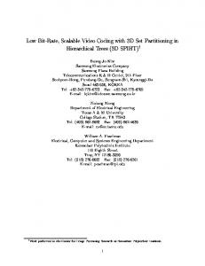
4.1. Description For recognizing project 3D objects in a site 3D laser scan, the developed approach requires the following data: (1) The registered 3D laser scan, and (2) the registered project 3D CAD model. It then follows a five-step process [11, 12]:
3. NEED FOR AUTOMATED OBJECTLEVEL 3D DATA COLLECTION (A3DDC) Many essential AEC control processes, that PIMs are intended to support, require monitoring the lifecycle 3D status of a project. They include:
Convert CAD model: The project 3D CAD model is converted into the open-source STereoLithography (STL) format. This format is chosen for two reasons: (1) it faithfully retains 3D information from the original CAD model, and (2) it enables a significant reduction in the computational complexity of the approach compared to more traditional formats.
Project progress tracking, Productivity tracking, Dimensional quality assessment and quality control (QA/QC),
Reference project 3D model in scan: The scan and model registration information is used to reference the STL-formatted project 3D model in the laser scan’s spherical coordinate frame
Life-cycle structural (dimensional) health monitoring, and Safety assurance.
Calculate as-planned scan: a virtual scan (or asplanned scan) is conducted using the referenced project 3D model as the virtually scanned world. In this scan, each as-planned point corresponds to exactly one point in the real scan (or as-built point): they have the same pan and tilt angles. Additionally, it is known in the virtual scan from which model object each as-planned point is obtained.
These activities require comprehensive life-cycle project 3D data be not only accurately acquired but also organized at the object level. For instance, progress tracking requires, among other aspects, identifying the project 3D objects that are built at given times. Then, dimensional QA/QC typically requires detailed 3D information be acquired for individual objects. Additionally, PIMs themselves typically organize project data from the bottom-up starting at the object-level. Automated Object-Level 3D Data Collection (A3dDC) would enable efficient project life-cycle 3D data management within PIMs, and thus support more efficient and reliable project performance control processes such as the ones mentioned above. However, very little progress has yet been achieved in A3dDC.
Recognize points: For each pair of as-planned–asbuilt range points, they are matched by comparing their ranges (they have the same pan and tilt angles). If their ranges are similar, the as-built point is considered recognized. Range similarity is checked with the following metric, where ∆ρ is the difference between the two point ranges (in mm) and ∆ρmin is an automatically calculated threshold:
281
4.2. Recognition Performances If ∆ρ ≤ ∆ρmin Then As-built point is recognized, Else As-built point is not recognized End
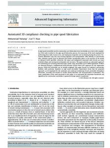
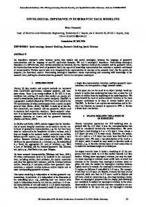
It has been demonstrated with experiments conducted with real-life data that this approach performs very well. Figure 2 shows the 3D CAD model, containing 612 objects, and a 3D laser scan, containing about 800,000 points, of the steel structure of a building part of a power plant project conducted in Toronto that was used for these experiments (see Acknowledgements).
In this metric, ∆ρmin is calculated automatically using the following formula where εReg is the mean registration error between the laser scan and the 3D model: ∆ρmin = εReg + 50
Several laser scans of this building were actually obtained, and on average, the developed approach achieved a recall rate of 76%, a specificity rate of 94% and a precision rate of 89%. While the specificity and precision rates are very high, the recall rate is not as good. The main reason for this lower rate can be found in the fact the model-scan registration was actually of poor quality (average mean registration errors of around 30mm). The point recognition metric takes the registration error into account in the calculation of ∆ρmin. However, it actually only partially takes it into account. Indeed, for some points the registration error may end up being in the same direction as their scanning directions, in which case the point recognition metric would properly account for it. But, for other points, this error may very well be in perpendicular directions, in which case the point recognition metric would poorly, if at all, account for it. However, large objects are rarely missed.
(1)
This calculation enables the recognition metric to take the two sources of uncertainty that are the registration/referencing error (εReg) and possible construction error (50) into account. Recognize object: Since it is known from which model object each as-planned range point is obtained, the as-planned range points, and consequently their corresponding as-built range points, can be sorted by object. The recognition of each object is then performed using the following metric where Surf is the covered surface of its recognized as-planned point and Surfmin is an automatically calculated threshold: If Surf ≥ Surfmin Then Object is recognized, Else Object is not recognized End
5. ENABLED PERFORMANCE MONITORING APPLICATIONS The developed approach enables A3dDC. Further, if 3D laser scans are acquired during the entire life of a project, the developed approach then enables the automated acquisition of the evolution of the 3D status of each of the model 3D objects over time. The resulting automatically constructed database, that can be referred to as the Project 4D Information Model (P4dIM) and that can be integrated as a part of the entire PIM, enables multiple applications related to the management of life-cycle 3D data.
The calculation of the covered surface of the recognized as-planned points of an object, Surf, is a function of the scan angular resolution and the asplanned point range and reflection angle. Then, the calculation of Surfmin is a function of the scan angular resolution and the maximum model distance to the scanner. This calculation of Surfmin enables the object recognition metric to take the scan angular resolution into account and ensures that, for each recognized object, at least five of its as-planned range points are recognized. And, overall, the object recognition metric is invariant with scan resolution and object-scanner distance.
5.1. Construction Progress and Productivity Tracking With the P4dIM, the recognition of the 3D objects in the 3D laser scans of two different days can be used
Figure 1 illustrates these five steps with an example. 282
to infer the progress and productivity of construction activities between these two days (see detailed analysis and experiments in [10]). Contrary to previously investigated ADC systems for progress tracking, that used indirect measuring methods ([6, 11]), this approach recognizes directly the quantities put in place (even partial objects like partially built brick walls) and so provides true progress and productivity measures. It must, however, be noted that not all construction activities can be monitored in terms of progress and productivity by collecting 3D information (e.g. painting). Reliable and efficient ADC for complete project progress and productivity tracking should thus consider fusing data and information from several monitoring systems such as the one presented here and those mentioned above. 5.2. Construction Dimensional QA/QC The developed approach organizes the dense scanned range point clouds per object. Therefore, for each object, the recorded point clouds can be used to assess its dimensional integrity. For instance, consider a structural concrete column with a cylindrical shape. Approaches matching primitives to point clouds such as those presented in [12] could be used to fit, in this case, a cylinder to the column’s range points. The fitting results could then be used to perform the following automated dimensional quality controls: Horizontal location: The horizontal location of the as-built column could be controlled by investigating Figure 1. Illustration of the process of the developed approach whether the horizontal location of the center point of the fitted cylinder is the same, within tolerances, to the horizontal location of the column in the (referenced) 3D model. Verticality: The verticality of the as-built column could be controlled by investigating whether the direction of the main axis of the fitted cylinder is vertical, within tolerances. Diameter and Length: The diameter and length of the as-built column could be controlled by investigating whether the diameter and length of the fitted cylinder are the same, within tolerances, to
Figure 2. 3D CAD model (left) and a 3D laser scan (right) of the steel structure of the investigated building.
283
those of the same column in the (referenced) 3D model.
of object 3D information considered critical for the investigated performance control processes.
Note that most designed and built 3D objects on AEC projects have primitive shapes or combinations of primitive shapes, so this approach could often be used. Otherwise, more complex fitting approaches could be investigated.
Further, the developed approach can be used to plan the project life-cycle scanning operations, and optimize the number of scans and their locations that would need to be performed during a project in order to ensure the acquisition of 3D information critical to specific project performance control processes.
5.2. Life-Cycle Dimensional Health Monitoring
It must be noted that occlusions due to non-model objects (e.g. equipment, temporary structures) are very common on construction sites, and may impact the results of this method for automated planning for scanning, since they are a priori unknown. In fact, the presence of non-model objects will always reduce the amount of 3D information actually scanned from the project objects. So, in general, scanned scenes should always be cleared as much as possible of non-model objects prior to conducting scans.
Similarly to dimensional QA/QC, during the project Operation and Maintenance (O&M) phase of a project the P4dIM would enable the automated monitoring of the project objects’ 3D dimensions over time. The structural health of a structure is often related to its dimensional integrity, particularly in the case of imminent failures. The developed approach for P4dIM would enable real-time dimensional and consequently structural health monitoring. Note that this is particularly interesting as 3D laser scans can be conducted remotely and consequently safely.
6.2. Strategic scanning Further than planning for scanning, the developed approach could be used in a reverse mode. As mentioned above, as-planned scans can be conducted prior to real scans to assess their expected 3D information content. Since, in an as-planned scan, it is known from which object each point is obtained, it would be simple to require the scanner on site to only scan those points of the objects that the performance from which control processes are interested in obtaining 3D information.
6. PLANNING FOR SCANNING AND STRATEGIC SCANNING Further than enabling real-time monitoring of project performances, the developed approach would enable two additional important applications: planning for scanning and strategic scanning. 6.1. Planning for scanning For each scan, the developed approach conducts, from the same position, a virtual scan using the project 3D model as the virtually scanned world. The assumption is that, if the building is built where it is intended to be, the project elements in the two scans should dimensionally match. The performances of the developed approach confirm that this assumption is correct. What this performance analysis does not clearly show, however, is that the calculation of the as-planned point cloud takes into account occlusions due to model objects on other model objects, so that a model object fully occluded in the real scan is also expected to be fully occluded in the as-planned scan. This implies that the developed approach can be used to test scanning positions prior to conducting the scans in reality, and investigate whether they would allow the acquisition
This is of great interest. Indeed, project managers who are currently dedicating resources to conduct project 3D scanning face the situation that they must save enormous amounts of scanned data, from which only a small portion is actually useful to their control processes. With the proposed approach, only useful 3D scanned data would be acquired, thus reducing the overall amount of data being stored during the life of a project. 7.
CONCLUSIONS
The AEC industry lacks efficient and reliable means of collecting comprehensive project 3D data automatically and at the object level. This paper presented a new approach for automatically and
284
Journal of Automation in Construction, Vol. 16, Iss. 2, 176–188. [5] Razavi, S. N., Young, D. A., Nasir, H., Haas C. T., Caldas C. H., Goodrum, P., and Murray, P. (2008) Field Trial of Automated Material Tracking in Construction , CSCE 2008 Annual Conference, Québec, QC, Canada, June 10–13 submitted. [6] Navon R. and Goldschmidt, E. (2002) Monitoring labor inputs: automated-data-collection model and enabling technologies, Journal of Automation in Construction, Vol. 12, Iss. 2, 185–199. [7] Brilakis, I. and Soibelman, L. (2008) Shape-Based Retrieval of Construction Site Photographs, Journal of Computing in Civil Engineering, American Society of Civil Engineers, Vol. 22, Iss. 1, 14–20 [8] Lynch, J. P., Partridge, A., Law, K. H., Kenny, T. W., Kiremidjian, A. S. and Carryer E. (2003) Design of Piezoresistive MEMS-Based Accelerometer for Integration with Wireless Sensing Unit for Structural Monitoring, Journal of Aerospace Engineering, Vol. 16, Iss. 3, 108–114. [9] Bosche, F. and Haas, C. T. (2008) Automated Retrieval of 3D CAD Model Objects in Construction Range Images, Journal of Automation in Construction, Vol. 17, Iss. 4, 499–512. [10] Bosche, F., Haas, C. T. and Akinci, B. (2008) Performance of a New Approach for Automated 3D Project Performance Tracking, ASCE Journal of Computing in Civil Engineering, Special Issue on 3D Visualization, submitted. [11] Sacks, R., Navon, R., Shapira, A., Brodetsky, I. (2002) Monitoring Construction Equipment for Automated Project Performance Control, Proceeding of the 19th International Symposium on Automation and Robotics in Construction (ISARC), National Institute of Standards and Technology, Gaithersburg, MD, USA, September 23–25, 161– 166.
reliably recognizing project 3D CAD model objects in construction site 3D laser scans. This approach enables the automated construction of the P4dIM – which can be integrated within the PIM, and consequently enables the automation (or at least strong computer-assistance) of many critical performance control processes. This system is complementary to other existing or investigated GPS, RFID, MEMS and embedded sensing systems, and could be integrated with them. Additionally, it is shown how this approach enables planning for scanning and even strategic scanning. This second application would help the AEC industry significantly reduce the amount of 3D data acquired and recorded during each project. 8.
ACKNOWLEDGEMENTS
This project is partially funded by the Canada Research Chair in Construction & Management of Sustainable Infrastructure. The authors would also like to thank SNC Lavalin and in particular Paul Murray for their support for this research, in particular for allowing Frederic Bosche to come to its project site, conduct some scanning and publish these results. REFERENCES [1]
[2]
[3]
[4]
Howell, G.A. (1999) What is Lean Construction, Proceedings of the 7th Annual Conference of the International Group for Lean Construction, IGLC-7, University of California, Berkeley, CA, USA, July 26–28, 1–10. Navon, R. and Sacks, R. (2007) Assessing research issues in Automated Project Performance, Automation in Construction, Vol. 16, Iss. 4, 474– 484. Saidi, K., Lytle, A. and Stone, C. W. (2003) Report of the NIST Workshop on Data Exchange Standards at the Construction Job Site, Proceedings of the 20th International Symposium on Automation and Robotics in Construction (ISARC), September 21– 25, Eindhoven, The Netherlands, 612–622. Navon R. (2007) Research in automated measurement of project performance indicators,
[12] Kwon, S.-W., Bosche, F., Kim, C., Haas, C. T. and Liapi, K. A. (2004) Fitting Range Data to Primitives for Rapid Local 3D Modeling Using Sparse Range Point Clouds, Journal of Automation in Construction, Vol. 13, Iss. 1, 67–81.
285