Automatic Addressing for DNA Microarray Images Lili Ma (+), YangQuan Chen (+), Dong Chen (*) and Bart Weimer (*) (+)
Center for Self-Organizing and Intelligent Systems Department of Electrical & Computer Engineering, 4160 Old Main Hill Utah State University, Logan, UT 84322 Emails:
[email protected],
[email protected] (*) Center for Integrated Biosystems, 4700 Old Main Hill Department of Electrical & Computer Engineering, 4160 Old Main Hill Utah State University, Logan, UT 84322 Emails:
[email protected],
[email protected] • Intensity Extraction: calculation of foreground Abstract intensities, and possibly quality measures. A method for automatic addressing the spots in DNA It is desirable for the addressing procedure to be as microarray images is introduced. Such a method reliable as possible to ensure accuracy of the whole considers variations in both translations and rotations measurement process. Existing methods to ensure within microarray batches with the hypothesis that the accuracy at the addressing stage include user spots in the microarray images are positioned interactions [6]. Available software allows the users to equidistantly both horizontally and vertically. The choose one of the images to serve as a template for the proposed automatic addressing method permits high whole batch of images. The user specifies the template thereafter throughput analysis and helps to minimize by mouse-clicking on the image boundary. In this user interactions. paper, we seek reliability while attempting to minimize user interactions and maximize the efficiency. Our proposed addressing method is Keywords: DNA microarray processing, automatic automatic. Further, the automatic addressing method addressing, algebraic circle fit. accounts for the variations in both translations and rotations within image batches. 1. Introduction Microarrays are matrix-shaped collections of DNA spots deposited on the surface of a glass or nylon slide. Each spot contains many copies of a single DNA sequence such as genes [1]. Signal processing algorithms have played a key role in facilitating data interpretation and understanding of microarray images [2]. Research has been directed to speed up the image processing by performing parallel processing in real time [3], image enhancement [4], image compression [5], and reliable pattern recognition [6]. In this paper, we present our results aiming at allowing automatic massive analysis of DNA samples. The processing of the scanned microarray images can be decomposed into three tasks [6]: • Addressing (gridding): assigning coordinates to each of the spots in a microarray image. • Segmentation: classification of pixels either as foreground, that is, as corresponding to a spot of interest, or as background that are the pixels out of the microarray spots [1]. The segmentation method produces a spot mask, which consists of the set of foreground pixels for a given spot.
215
2. Image Processing Microarrays are part of a new class of biotechnologies that allow the monitoring of expression levels for thousands of genes simultaneously. Image analysis is an important aspect of microarray experiments, one that can have a potentially large impact on subsequent analyses such as clustering or the identification of differentially expressed genes [6]. The objective of the image processing module is to extract the features of the spots in the DNA microarray images. Our method outputs the centers and the radii of the circles representing the DNA patterns, given a batch of images of the same structure. In particular, we emphasize on the automatic addressing method that allows both translations and rotations within image batches, and the algebraic circle segmentation method where the circles’ diameters are estimated separately. The image processing algorithms for the spot analysis are first summarized in the following: • Automatic Addressing: global addressing of the spots with minimal human interactions (without user mouse-click to decide the image
•
boundary) based on the hypothesis of the number of columns and rows in the images. Independent Circle Segmentation: circles’ diameters are estimated independently and separately for each spot.
•
Partition of the whole image into individual cells, using the angles of the two fitted lines, the distance between the two fitted lines, and the knowledge of totally 8 × 12 cells of equal size.
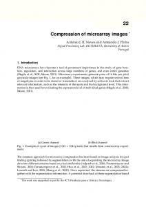
2.1. Automatic Addressing The addressing method relies on the concept of a batch of image data. For the purpose of image analysis, a batch is a collection of microarray images whose overall geometric structure is the same. The geometry of images can vary in a number of ways [6]: • Basic Structure: arrangement of spots within grids (we require images within a batch be identical in terms of this basic structure). • Translation: shift in all spot positions from image to image (we expect such variations within batches). • Rotation: rotation of the image with respect to a template (we expect such variations within batches). The basic structure of a microarray image is determined by the researcher and is therefore known. This is a common assumption and is also adopted here. An addressing method that can deal with translations in the microarray images has been described in [6]. Variations in the rotations is considered in this paper. The objective of the addressing method is to locate the regions of each subimage or cell. Without this step and just by applying a universal threshold to the whole image, spots of insignificant densities might not be detected successfully. After this addressing procedure, segmentation and circle fit can be applied to individual cells separately and locally. Some previously unobserved densities can be detected. Figure 1 illustrates our automatic addressing method in details. The method is described below: • The input gray-level image. • Binary image after applying a threshold to the input image. The threshold is determined via the well-known Otsu's method [7]. • Coarsely extracted edges of the spots in the first two leftmost columns. Circle fit to the detected spot boundaries. The output of the circle fit is the center and radius of the detected edge boundary. • Line fit to the centers of the fitted circles. Computation of the distance between the two fitted lines.
216
Fig. 1: Automatic addressing of a DNA image.
2.2. Circle Segmentation After the addressing and given the extracted boundary of a spot, circle segmentations are performed locally using a simple algebraic algorithm [8]. By outputting the center and radius of a circle, pixels of the foreground are specified as belonging to the spot and can be used for density computations. Moreover, ellipse fitting algorithm can be applied by specifying the x-radius and y-radius of an oval to recognize genes of more general shapes. In the next, the algebraic circle fit algorithm is described. When the radius of a circle is unknown, an algebraic circle fitting method can be applied in the least square sense. That is, given a set of points (which are the detected edge pixels of the spots in interests) with coordinates {( xi , yi ), i = 1, 2, K , n}, find the best parameters (a1 , K , a 4 ) in the circle equation [8]: a1 ( x 2 + y 2 ) + a 2 x + a3 y + a 4 = 0 , such that the algebraic error is minimized. Denote r a = [a1 , a 2 , a 3 , a 4 ]T and construct a matrix D as: ⎡ x1 2 ⎢ 2 ⎢ x2 D = ⎢ x3 2 ⎢ ⎢ ⎢ 2 ⎣ xn
+ y1 2
x1
+ y2
2
x2
+ y3
2
x3
M
+ yn
M 2
xn
y1 1⎤ ⎥ y 2 1⎥ y 3 1⎥. ⎥ M M⎥ ⎥ y n 1⎦
r r We can have D a = 0 . The circle parameters a can be obtained as the least square solution of the above equation. A typical circle fit to the extracted spot boundary is shown in Fig. 2.
check on the estimated spots and, if it is the case, to eliminate unreliable estimations. Function 1: When the number of the detected edge pixels in a subimage is greater than a predefined threshold, threshold1, the edge pixels are fed into the algebraic circle fit function described before, whose output includes the center and the radius of the edge pixels. Figure 3 shows an example of the circle fit using Function 1.
Fig. 3: Example of circle fit using Function 1. Function 2: When the observed spot in the subimage is small, the density is low, or the detected edge pixels are noisy, Function 1 may fail. In this case, image enhancement operators need to be applied for noisy pixel removal. Simple image dilation operator to remove small objects is used for this purpose [9]. After the image dilation, when the number of pixels in the detected edge is greater than another predefined threshold, threshold2, these edge pixels are fed into the circle fit function to fit the center and the radius. An example of the spots that can be recognized by Function 2 is shown in Fig. 4, where the processing steps include: 1) edge detection of the input subimage, 2) image dilation operation, 3) edge detection again, 4) select the largest group of connected pixels, 5) circle fit to the selected edge pixels, and finally 6) circle fit displayed in the original input subimage. In our implementation, the predefined thresholds, the threshold1 and threshold2, are manually tuned. These thresholds need to adapt to particular applications.
Fig. 2: Algebraic circle fit to the spot boundary.
2.3. Boundary Extraction of Each Subimage Given the subimages segmented using the addressing method described earlier, two functions are applied to extract the boundaries of the spots, where the second function will be applied when the first function fails. These two functions act in a sequence based on the number of the detected edge pixels of each spot. The reason for applying such a sequence of functions is to maximize the possibility of detecting possible gene spots candidates. In cases where deleting some spots is better than the risk of reading the wrong information [3], an extra step can be used to perform a quality
217
Fig. 4: Example of circle fit using Function 2. When the observed spot in the input subimage is extremely small, Function 2 may fail. Since the image dilation operation performed in Function 2 has an
adverse effect of making the objects smaller, we can search through a region close to the center for connected components of the largest size. Doing this way, we assume that the DNA pattern, if any, evolves around the center of each cell. It needs to point out that using the above functions, it is not guaranteed that we can always detect a circle for a given subimage. In these cases, there is barely anything noticeable in the given subimage.
performance in handling image variations in both translations and rotations within microarray batches. Segmentation methods are also described aiming at maximizing the possibility of detecting gene spots candidates.
4. References [1]
2.4. Final Processed Images Using the automatic addressing and the algebraic circle segmentation methods described before, Fig. 5 shows two examples of the processed microarray images where the fitted circles are displayed in the original input images. Notice that, in the first two leftmost columns, circles that are plotted in green denote those fittings used for the automatic addressing when applying a universal threshold to the whole image. After the global segmentation, local thresholds are used for the detection of the edge pixels of individual spots. Circle fittings to the locally detected edge pixels are plotted in blue.
[2]
[3]
[4]
[5]
[6]
[7]
[8]
[9]
Fig. 5: Examples of the processed microarray images.
3. Conclusions In this paper, an automatic addressing method for DNA microarray processing is proposed to minimize user interactions and further speed up the image processing. The proposed method can achieve robust
218
C. Nicolini, A. M. Malvezzi, A. Tomaselli, D. Sposito, G. Tropiano, and E. Borgogno, “DNASER I: Layout and Data Analysis,” IEEE Transactions on Nanobioscience, 1(2), pp. 67 – 72, June 2002. J. Patrick Fitch and Bahrad Sokhansanj, “Genomic Engineering: Moving Beyond DNA Sequence to Function,” Proceedings of the IEEE, 88(12), December 2000. P. Arena, M. Bucolo, L. Fortuna, and L. Occhipinti, “Cellular Neural Networks for RealTime DNA Microarray Analysis,” Engineering in Medicine and Biology Magazine, IEEE, 21(2), pp. 17 – 25, 2002. M. K. Szczepanski, B. Smolka, K. N. Plataniotis, and A. N. Venetsanopoulos, “Enhancement of the DNA Microarray Chip Images,” Proceedings of Digital Signal Processing, vol. 1, pp. 403-406, July 2002. Rebecka Jornsten and Bin Yu, “Compression of cDNA Microarray Images,” IEEE International Symposium on Biomedical Imaging, July 2002. Y. H. Yang, M. J. Buckley, S. Dudoit, and T. P. Speed, “Comparison of Methods for Image Analysis on cDNA Microarray Data,” Journal of Computational and Graphical Statistics, vol. 11, pp. 108-136. N. Otsu, “A Threshold Selection Method from Gray-Level Histograms,” IEEE Trans. on Systems Man Cybernetics, 9(1), pp. 62-69, 1979. Zhen Song, Yangquan Chen, Lili Ma, and You Chung Chung, “Some Sensing and Perception Techniques for an Omnidirectional Ground Vehicle with a Laser Scanner,” IEEE Int. Symposium on Intelligent Control, pp. 690-695, October 2002. David Forsyth and Jean Ponce, “Computer Vision - A modern approach,” Third Edition, Prentice Hall, August 2003.