engaging in very dangerous acts, such as putting actors in fire, smoke, water ... dynamic texture to fill a background hole or damages area, as described by .... B. Angle Measurement and Mean Value ...... 88.77), although the reflection from the water surface has occurred. .... 180o and 270o in clockwise rotations are used.
This article has been accepted for publication in a future issue of this journal, but has not been fully edited. Content may change prior to final publication. Citation information: DOI 10.1109/TCSVT.2015.2469552, IEEE Transactions on Circuits and Systems for Video Technology
> PAPER IDENTIFICATION NUMBER: 9642
PAPER IDENTIFICATION NUMBER: 9642
PAPER IDENTIFICATION NUMBER: 9642
PAPER IDENTIFICATION NUMBER: 9642
PAPER IDENTIFICATION NUMBER: 9642 < The template partition process starts by seeding a number of random points on the motion vector field of TOI. The motion vector field of TOI is divided by horizontal and vertical lines drawn through the random points, as shown in Figs. 10(a) and (c). The system then randomly enlarges the block size by extending the width and/or height to obtain non-periodic tiling blocks, as shown in Figs. 10(b) and (d).
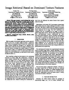
(a) The 3D waterfall patches and the average motion angles.
(b) The 3D smoke patches and the average motion angles.
(c) The 3D fire frame patches with the average motion angles. Fig. 11. Illustration of 3D patches where the estimated motion directions were expressed under the patches. The orange lines represent the vectors and the green dots represent the central point of 3D surface block in equal distances.
In the partition stage, let a = (a1, a2, …, an) be a set of random coordinates in a sequence order on a video frame (Ф2) with size c×r. There exist n vertical and n horizontal lines which are drawn through each point ai, where i = 0, 1, …, n. Let v = (v1, v2, …, vn) and h = (h1, h2, …, hn) represent the sets of vertical and horizontal lines, respectively. The vertical line v1 consists of the contiguous pixels lying on x1 in the 2D x-y plane, namely (x1, 1), (x1, 2), …, (x1, c). The horizontal line h1 consists of the contiguous pixels lying on y1 in the 2D x-y plane, i.e. (1, y1), (2, y1), …, (r, y1). Hence, the coordinate a1 = (x1, y1) represents the intersection of v1 and h1, a2 = (x2, y2) represents the intersection of v2 and h2, and an = (xn, yn) represents the intersection of vn and hn, respectively, where 0 < x1 < x2 < … < xn < c and 0 < y1 < y2 < … < yn < r. Let N be the number of rectangle blocks derived from the intersections of v and h. Then, N is calculated by (10): 2 (10) N = ( n +1) For the distance between xi and xj, or yi and yj, if (xj – xi) or (yj – yi) is greater than a given threshold (in our experiment we set the threshold as 50 pixels; however, it depends on the size of target videos) an extra vertical or horizontal line will be added between xi and xj or yi and yj, where j = i+1 and i =1, 2, …, n–1. The contiguous pixels on new vertical line v, are lying on x+, where x+ is determined by (11), and the contiguous pixels on new horizontal line h, are lying on y+, where y+ is determined by (12): ! x + xj # (11) x+ = ! i # " 2 $ ! y + yj # (12) y+ = ! i # " 2 $
7 Assume k represents the number of extra vertical lines and d represents the number of extra horizontal lines. Therefore, N can be calculated by (13): (13) N = ( n + k +1) × ( n + d +1) where k and d are independent, and k, d ≥ 0. The purpose of 3D patch production is to obtain the patches in 3D derived from the target video frame (Ф2). The results are demonstrated in Fig. 11. The motion vectors produced by the Farnebäck polynomial expansion-based optical flows are automatically partitioned into the patches. The average motion angle on each patch is calculated by (2), and represents the motion direction of the patch in the temporal space from time t to t+1. Suppose Ω2 represents the patch that consists of n vectors. Let αi represent the motion angle of vector i on patch Ω2, where i = 1, 2, …, n. The attribute value of patch motion direction is represented by α , calculated from n vectors on a patch Ω2 according to (2). The decimal numbers demonstrated under the images in Fig. 11 represent the attribute α . The value α is used for patch matching, which will be described in section III-E. D. Motion Coherence Analysis
(a) A simulation of two incoherent (b) A simulation of two coherent vectors (opposite directions) vectors demonstrates the coherence demonstrates the coherence index index equals to 100.0. equals to 0.0. Fig. 12. Demonstration of two simulation vectors for motion coherence analysis. The coherence index was calculated by our proposed method.
We propose a new efficient metric for calculating the motion coherence between two patches. Let Ω2 represent a patch derived from the 3D patch production process. The value α represents an average motion angle of n vectors calculated by (2). The value α is used to describe the motion angle of patch Ω2. There must exist ψ2 that represents a patch derived from a source video frame (δ2). The patch ψ2 consists of n vectors. The motion angle of a vector on ψ2 is represented by θ, in a similar manner. The value θ represents an average motion angle of n vectors on ψ2 calculated by (2). Here, αi and θi are measured in radian, varying from 0.0 to 2π. The beginning point is with the radian 0.0, at (x, 0) on the x-y plane. The radian is counted in the clockwise direction with the radius
x 2 + y2 . The coherence index is proposed to calculate the motion coherence of two vectors, as demonstrated in Fig. 12. Fig. 12 shows the simulation results of coherent and incoherent motion between two vectors. The coherence index varies in a floating range between 0.0 and 100.0. If the two vectors are coherent, the coherence index will be 100.0. In contrast, if the two vectors are incoherent, the coherence index will be 0.0. The measurement aims to evaluate the consistency of the two radians, since a surface block will move along the radian. For
1051-8215 (c) 2015 IEEE. Personal use is permitted, but republication/redistribution requires IEEE permission. See http://www.ieee.org/publications_standards/publications/rights/index.html for more information.
This article has been accepted for publication in a future issue of this journal, but has not been fully edited. Content may change prior to final publication. Citation information: DOI 10.1109/TCSVT.2015.2469552, IEEE Transactions on Circuits and Systems for Video Technology
> PAPER IDENTIFICATION NUMBER: 9642