projects that require conformance with the Life Safety Code (LSC) of the National Fire Pro- tection Association (NFPA) (Lathrop 1985). There is a growing ...
AUTOMATIC FIRE-CODE CHECKING USING EXPERT-SYSTEM TECHNOLOGY By Ethymios A. DelisI and Alex Delis 2 A significant part of the engineering design process is devoted to checking the compliance with codes that result from legislation. The code-checking process requires deep knowledge of the regulations, awareness of changes, good understanding of the design process, and, most importantly, skillful personnel. Automatic intelligent fire-code checking is examined in this paper. A general approach is considered wherein engineering code requirements are encoded in a knowledge-based expert system that evaluates a design for overall conformance. The system, termed Fire-Code Analyzer (FCA), consists of a frame system, a rule system, and a set of geometric algorithms. The frame-based system is used to represent the various three-dimensional objects of an application model and their relations. The rule-based system includes a set of rules in the IF/THEN form, and its purpose is to provide all the necessary information to achieve compliance with codes. A number of geometric algorithms that elicit knowledge from the frame representation of the various building objects are discussed. The system identifies code violations and generates a report listing them.
Downloaded from ascelibrary.org by UNIVERSITY OF PITTSBURGH on 03/10/16. Copyright ASCE. For personal use only; all rights reserved.
ABSTRACT:
INTRODUCTION
Engineering design is an iterative and time-consuming process that requires expertise from diverse fields. An important part of the design process is devoted to checking the compliance of a design with one or more codes that might result from legislation (federal, state, and local). The code-checking process requires deep knowledge of the codes, awareness of their continuous changes, good understanding of the design process and, most important, skillful personnel. The goal of this paper is to address the application of artificial intelligence techniques to engineering projects that require conformance with the Life Safety Code (LSC) of the National Fire Protection Association (NFPA) (Lathrop 1985). There is a growing interest within the engineering design and construction industry to develop intelligent computer programs to review designs in conformance with various codes and specifications (Fenves and Rasdorf 1985; Gero et al. 1984; Maher and Fenves 1985; Niwa 1987; Maher 1987). The early proposed solution of converting engineering codes into "hard-coded" conventional programs is not realistic due to the frequent revision of codes. Other promising paths have to be explored. One of them is to develop a system that could overcome most of the aforementioned problems and also use human-like reasoning. Because of its complexity, code-checking in engineering design is a challenging area and a real opportunity for application of artificial intelligence techniques (Rich 1983). There are mainly four reasons for this: • •
Code-checking has a well-defined goal; that is, conformance of the application model with the code(s)-but this is not a trivial task. The knowledge of codes (domain knowledge) can be acquired from the code-documents and their commentaries promulgated by the authorities having jurisdiction. Experts in codes can teach how to apply code knowledge to a given case. They can also formulate and highlight the main points of the code-checking in a reviewing protocol format. Such a system would be a real asset to and an invaluable tool to many designers in practice.
This paper discusses the design and implementation of the Fire-Code Analyzer (FCA) prototype that is an expert system for fire-code checking. It also presents a number of algorithms used by the prototype to infer information from the explicitly furnished input data of buildings. A preliminary presentation of the system was reported in Delis and Delis (1991). The Fire-Code Analyzer is an extension to the LSC ADVISOR developed at the University of Massachusetts (Dym et al. 1988). The FCA provides a more versatile frame-based representation of floor plans, creating a more eleborate rule-based system to handle three-dimensional (3D) issues. It 'Tech. Staff Member, Delta Engrs., 2840 Grasslands Dr.. Sacramento, CA 95833. 'Lec1., School of Information Systems, Queensland Univ. of Technol., 2 George S1., GPO Box 2434, Brisbane, Queensland 4001, Australia. Note. Discussion open until September I, 1995. To extend the closing date one month, a written request must be filed with the ASCE Manager of Journals. The manuscript for this paper was submitted for review and possible publication on December 28, 1993. This paper is part of the Journal o!Computing in Civil Engineering, Vol. 9, No.2, April, 1995. ©ASCE, ISSN 0887-3801!95/0002-0141-0156/$2.00 + $.25 per page. Paper No. 7590. JOURNAL OF COMPUTING IN CIVIL ENGINEERING
J. Comput. Civ. Eng., 1995, 9(2): 141-156
141
Downloaded from ascelibrary.org by UNIVERSITY OF PITTSBURGH on 03/10/16. Copyright ASCE. For personal use only; all rights reserved.
also utilizes a set of geometric algorithms to facilitate knowledge inference. The FCA has been developed to assist in the review of building designs. These designs need to satisfy the requirements of the Life Safety Code (LSe) (Lathrop 1985). The LSC is a set of provisions for fire protection that all types of buildings have to comply with. The organization of the paper is as follows: in the next section, we introduce the problem of the design in engineering, outline its complexity, and briefly describe the role of the Life Safety Code (LSC) in this process. Then we review related work and compare it with our own. Then we provide an overview of the FCA design and implementation, describe FCA's main functional components, and present an output sample of the system. Five of the geometric algorithms used are discussed in detail in the section headed "Description of Geometric Algorithms." A summary and future directions can be found in the last section. BUILDING DESIGN PROCESS
The purpose of a design process is to create a description that satisfies building functional specifications, requirements on performance and resource usage, restrictions on the design process itself such as its length and cost, as well as restrictions on the tools available for carrying out the design process (Mostow 1985; Broadbent 1973). A building design is the result of two major disciplines, architecture and structural engineering, and other engineering fields, such as mechanical and electrical engineering, also play an important role. The main stages of the design are Preliminary design: Alternative structural configurations are explored in order to give a certain shape to the structure, and many tests are performed to check whether the building serves its purposes and satisfies its constraints. Structural analysis: The structural system should be able to support itself. At this stage, the structure is analyzed and the results of the analysis are evaluated. Detailed design: Major changes in the structural system are usually not expected at this phase. The structural components and their connections are selected to satisfy the design objectives. In engineering practice, structural analysis and detailed design are iterative processes that are continued until convergence is reached. Therefore, it becomes evident that the design process is not a task of ordinary complexity and medium effort. A partial automation of the process would provide considerable financial gains. In order to achieve this goal, integrated design systems were introduced in engineering. Integrated Design Systems and Codes
An integrated system consists of a database management system and a number of subsystems. These subsystems can be either conventional algorithmic programs or knowledge-based expert systems or a combination of both (Eastman 1981; Spoonamore et al. 1982; Balachandran et al. 1991). The main issue in the development of an integrated system is the creation and maintenance of the database, which serves a number of functions. Such functions include graphic representations, input/output facilities, evaluation, optimization, planning, control, etc. Much of the data residing in the system's database should be checked against standards imposed by authorities. The purpose of these standards is to regulate construction in order to assure the safety, health, and general welfare of the occupants of buildings. Codes refer to matters such as fire protection, building materials, construction procedures, seismic design, lighting, ventilation, plumbing, etc. Most building codes used to be of a specification type, which regulated materials, designs, and construction procedures. With the further regulations on these three categories, a new necessity emerged-greater code flexibility. This led to the transition from specification-type to performance-type codes, which provide requirements in terms of needs to be met without limiting the materials, designs, or construction procedures to be used. Due to these developments and frequent changes, building codes now consist of a large number of pages, and they are promulgated by various authorities with jurisdiction in federal, state, county, municipal, and zoning levels, as well as by health departments and insurance companies. Since each of these authorities establishes its own codes, there is a lack of uniformity among those codes on the same issue. Despite recent efforts, it seems unlikely that code uniformity will be achieved in the near future. Life Safety Code (LSC)
Fire codes and standards are an integral part of building codes. Reznikoff (1979) estimates that 75% of all building codes are related to fire protection. One of the fire codes and probably the most important one is the Life Safety Code. This was issued by the National Fire Protection Association (NFPA), which has been the publisher of this code for over half a century. 142
JOURNAL OF COMPUTING IN CIVIL ENGINEERING
J. Comput. Civ. Eng., 1995, 9(2): 141-156
Downloaded from ascelibrary.org by UNIVERSITY OF PITTSBURGH on 03/10/16. Copyright ASCE. For personal use only; all rights reserved.
The purpose of the LSC is "to establish minimum requirements that will provide a reasonable degree of safety from fire in buildings and structures" (Lathrop 1985). Although the LSC is primarily concerned with the life safety, it provides at the same time a certain degree of property protection. The provisions that the LSC establishes apply not only to new constructions, but also to existing facilities. The most important parts of the LSC are those that refer to means of egress and features of fire protection. They apply to all kinds of buildings with some modifications. Means of egress include the exits, the exit access, and the exit discharge. Its requirements concern travel distances, exit capacity, the arrangement, type, width, and the number of exits, as well as their identification and lighting. Features of the fire protection comprise construction, protection of vertical openings and concealed spaces, fire and smoke barriers, interior finishes, and protection from hazards. Requirements regarding means of egress and features of fire protection apply to all kinds of buildings, with some modifications that depend on the type of the facility. Types of facilities include hotels, dormitories, apartment buildings, lodging houses, family dwellings, as well as assembly, educational, health care, detention, mercantile, business, storage, and industrial occupancies. RELATED WORK
This section reviews undertaken efforts toward automation of the code-checking process. Goel and Fenves (1969) described a computer program that checks a design for conformance with a standard represented by a network of decision tables. A decision table can be defined as a concise tabular presentation of logical conditions applicable to a given situation and the appropriate actions to be taken as a result of the values of these conditions (Cronembold and Law 1988). Fenves (1979) and Fenves and Rasdorf (1985) focused on interpreting provisions and requirements and converting them into "programmable processing steps." Specifications are represented as networks of decision tables. The issue of automatic conversion of the decision tables into design tools is discussed in Holtz and Fenves (1980). Stahl et al. (1983) developed a computer program called SASE (Standards Analysis, Synthesis and Expression) for code expression and formulation. Howard and Fenves (1983) addressed the problem of comparing specifications of several seismic design codes. STEEL-3D (Pesquera et al. 1984) is an advanced graphics CAD system for designing threedimensional steel frames and performs analysis in compliance with the American Institute of Steel and Construction (AISC) code (Specification 1978). ECPRS (Warren 1984) is an interactive computer-aided design program that designs reinforced concrete members. All design decisions are completely documented by ECPRS according to American Concrete Institute (ACI) 31883 code, and this documentation is presented as a part of the program output. Lopez and Elam (1984) developed SICAD, which incorporates a model to represent design standards, a simplified database, and an expert system application program that performs conformance evaluation. Gero et al. (1984) focused on the applications of artificial intelligence techniques in architectural design. Their work addresses the issue of knowledge acquisition in a computer-aided architectural design environment. One of the goals in developing and testing the prototype expert system BUILD (Rosenman and Gero 1985) was to analyze the requirements of an expert system for design codes and to demonstrate the capabilities of such an approach. The system includes a restricted "natural" English representation of parts of the Australian Building Code. HI-RISE (Maher and Fenves 1985; Maher 1987) was an expert system suitable for preliminary structural design of high-rise buildings. Garrett and Fenves (1986) developed SPEX, a prototype knowledge-based system suitable for the design of structural components. SPEX determines component material, structural, and geometric properties that are in conformance with the applicable design standard. Computer-Assisted Sprinkler Engineering (CASE) (First 1986) assists architects in designing sprinkler systems for commercial buildings. The FireCode system (Buis et al. 1987) checks designs against New Zealand fire regulations and proposes options when requirements are not met. Finally, Construction Code Consultation System (CCCS) (Niwa 1987) is a knowledge-based system for code-checking for compliance with the Japanese Building Code. The system includes a CAD system and a natural-language interface in Japanese. The FCA Analyzer is closely related to SICAD, CASE, and FireCode projects mentioned earlier, but it differs in at least three aspects: It successfully uses an off-the-shelf expert system shell (KEE). Since KEE allows its
knowledge bases to be organized in an hierarchical manner and provides flexible mechanisms for modifying this hierarchy, regulations can be either added or alternated with a reasonable effort. • It deals with almost all the important aspects of the fire protection code as they are stated by the LSC document for this problem domain used in the prototype version of the FCA. JOURNAL OF COMPUTING IN CIVIL ENGINEERING
J. Comput. Civ. Eng., 1995, 9(2): 141-156
143
•
A number of geometric algorithms are used in order to automatically elicit knowledge from the structural layouts of the examined buildings.
Downloaded from ascelibrary.org by UNIVERSITY OF PITTSBURGH on 03/10/16. Copyright ASCE. For personal use only; all rights reserved.
SYSTEM DESIGN AND IMPLEMENTATION
To meet the challenge of code-checking, a useful environment should provide: (1) Appropriate mechanisms to choose only those requirements applicable to a given design, (2) an interface to the design database, (3) constructive mechanisms, which could protect code-compliance of the application model from side effects or undesirable changes due to code interaction [interactive subproblems (Barr et al. 1981)], (4) a proper framework, which would allow easy incorporation of new codes for future expansion of the system, (5) code modularity, so that the system developer can make changes in a particular part (for instance, in a knowledge base) without disrupting the structure of the whole system, (6) code granularity; that is, the proper level of details required to represent accurately the various paragraphs of codes, (7) an easier checking procedure which would avoid the repeated testing of the application model on the same subject(s) because of overlapping codes, and (8) flexibility, which would enable the designer to select only parts of the code(s) to test an application model against them. The prototype expert system presented here provides a framework in which all of the above questions could be resolved in a structured fashion. The Fire-Code Analyzer, consists of a rule-based system, a frame-based system, and a set of geometric algorithms. It has been implemented in the Knowledge Engineering Environment (KEE) developed by Intellicorp (1988). KEE is a set of software tools designed to assist system developers in building knowledge-based expert systems. One of its major advantages is its ability to integrate a frame system with a rule-processing system. Besides, it offers graphics for flexible and easy to construct user interfaces and object-oriented programming for handling data-dependent programming requirements. The programming language used was Common LISP.
Rule-Based System The rule-based system consists of the knowledge base and the rule interpreter. The knowledge base includes a set of rules that represent unordered declarative pieces of code knowledge. In the proposed system, specifically, a rule basically represents a paragraph of the Life Safety Code. Rules consist of two parts: an antecedent and a consequent component. [f the antecedent component is satisfied, then the consequent one is satisfied too. When the consequent component defines a conclusion or an action, the effect will be to draw the conclusion or to schedule the action for the next execution respectively. The paragraph of the LSC 12-3.1 concerns protection of vertical openings and its exception #3 reads The fire resistance rating of enclosures in health care occupancies protected tllroughout by an approved automatic sprinkler system may be reduced to 1 hour in buildings up to. and including, three stories in height. This paragraph can be translated into the following rule, which is a part of the code representation in the rule-based system. (IF (AND (THE SPRINKLER-PRESENCE OF A BUILDING IS YES) (?SPACE IS IN CLASS VERTICAL-OPENINGS) (THE SUPERSPACE OF ?SPACE IS ?ZONE) (?ZONE IS IN CLASS FIRE-ZONES) (LISP « (THE STORIES-ABOVE-GRADE OF BUILDING) 4))) (THEN (A REQUIRED-ENCLOSURE-RATING OF ?SPACE IS 1)))
[I] [2J [3J [4J [5J
When the presence of a sprinkler system in the building is assured (clause 1), the following clauses (clauses 2, 3, and 4) focus attention on those vertical openings (?SPACE) in the fire zone under investigation (?ZONE) that belong to vertical openings (such as stairway. elevators. ventilation chutes, etc.) between stories. The fifth clause compares the legal number of stories of the building. The result of this rule is that the slot REQUIRED-ENCLOSURE-RATING. which already exists in the frame ?SPACE vertical opening, takes the value 1. The rule interpreter matches the antecedent component to the facts regarding application model (i.e., building) information from the frame-based system. Generally, this requires pattern matching to find constants in the frame system that match identical constants or unbound variables in the rules. The rule interpreter performs forward and backward chaining, which are built-in mechanisms in the KEE tool. They enable the system to perform data-directed and goal-directed reasoning. Contrary to many other problem domains, the code-checking process in LSC requires an exhaustive search for identification of all potential problems that can be associated with a 144
JOURNAL OF COMPUTING IN CIVIL ENGINEERING
J. Comput. Civ. Eng., 1995, 9(2): 141-156
Downloaded from ascelibrary.org by UNIVERSITY OF PITTSBURGH on 03/10/16. Copyright ASCE. For personal use only; all rights reserved.
particular type of facility. It has been shown that the overall performance of the system is satisfactory under forward chaining control strategy. For instance, it takes about 12 sec for our prototype to complete checking of a floor plan that is made up of 10 rooms with three to four corridors on a Texas Instruments Explorer. A rule-based representation of the LSC requirements is used in the system for a number of good reasons. Such a representation Modularizes chunks of knowledge like those that appear in the various paragraphs of the code Supports a gradual development of the system Keeps a high level of abstraction of the requirements similar to the one in the LSC Facilitates the easy maintenance of the system over a period of time Frame-Based System
The frame-based system is used to represent the architectural features of a building (Fikes and Keller 1985). Each frame of the system clearly represents an object and its properties. A set of frames can describe a complex model (e.g., a building) that consists of many objects in a well-organized manner. Frames consist of a number of slots that are used to describe the attributes of an object or a class of objects. There exist two procedural attachments to frames: procedures and active values. Procedures are also called methods and are functions written in LISP. Active values or demons are methods that become activated when they are attached to or removed from slots or when slot values are accessed or changed. An example of the frame DOORI is given in Fig. 1. The label CALC indicates that the slot values are calculated by using a method; and the label INP indicates input data given by the user her- or himself. Since a frame can point to another frame, it can indicate an inheritance relation. Inheritance hierarchies are used to minimize redundant input information. When new objects are created they inherit attributes of the generic objects, and therefore, the system developer has to input only specific information associated with the new objects. Frames are organized in a hierarchical way (Fig. 2) using two types of links between the various frames: memberlinks (i.e., dashed arcs), which indicate class membership (i.e., "is-a" relationship) and subclass links (i.e., solid arcs), which indicate specialization on containment (i.e., "part-of" relationship). For example, in Fig. 2 the frames FLOOR1, FLOOR2, FLOOR3, and FLOOR4 are members of the class frame FRAME. The FRAME contains general information about the building such as its dimensions, type of structure, etc. Every floor frame is organized into AREAS and NODES. The further organization of each of these frames is shown in Fig. 2. There are at least three reasons for using a frame-based system in the proposed system. First, it can represent the various building objects in a concise way. Second, it facilitates the expression of relations among the frames (i.e., relations among the various building objects). Third, a number of algorithms that have been developed make use of the frame structure in order to rapidly perform inferences. Geometric Algorithms
A series of new geometric algorithms have been developed or are under development in order to meet the specific needs of the FCA. The main purpose of these algorithms is to make explicit the implicit information stored in the frame system regarding the various features of the building at hand. A description of five such algorithms is given in a subsequent section. Additional algorithms of either lesser computational interest were coded in the development phase of the I Frame: I Slot
DOORI
I Valu.Cla.. I SourC% I Comment
CONNECTED..5PACE NETJlREADTB RATING SWINGSJNTO TRAVEL..DIS_TO..EXIT BREADTB FCA-PROBLEM COORDS INROOM_TRAVEL..DIS AREA WALL :IEIGBT NUMJ.EAVES DOOR-TYPE EXlT-PATB VlSION-PANEL
FIG. 1.
NIL NUMBER NUMBER NIL NUMBER NUMBER STRlNG NIL NUMBER NUMBER STRlNG NIL NUMBER NIL NIL NIL
CALC INP INP INP CALC CALC CALC INP CALC CALC CALC INP INP INP CALC CALC
ROOMS and CORRlDORS connected by this DO R Feet BoW'll ROOM or CORRlDOR into ...hich this DOOR ....ina Travel Distance in feet Groos Breadth in feet D~Pl ~P2
(a)
12
P'
#r 4
,
.,
("~
, ,,
·· ··
P6
•
P5
P6
PI
,
(e)
P2
lal
(bj
FIG. 6. Travel Paths within Corridor
FIG. 7.
Cases In Network of Corridor Nodes
JOURNAL OF COMPUTING IN CIVIL ENGINEERING
J. Comput. Civ. Eng., 1995, 9(2): 141-156
149
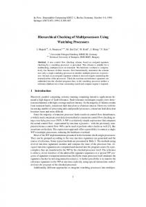
Heu~istic: Fo~ a given set of four vectors [i.e. (P;P i +I' Pi +IPi +2) and (PjP j+I' P;+ IPj+2)] if P,Pi +I IS an active vector over PjPj+I and Pi +IPi +2 is not, then create a corridor node at the midpoint of Pi +I and Pj+I otherwise, find the projection of Pi +I on PjPj+I (e.g., P;+ I) and create a corridor node at the midpoint of Pi + I Pi + I' For example given the set of four vectors of Fig. 7(b), PIP, is active with respect to P2P4 but P,P5 is not active with respect to P2P4 • Therefore, a corridor node is created at the midpoint of P,P4 • In Fig. 7(c), the projection P!" of point P, on vector P2P4 is found and a corridor node is created at the midpoint of P,P!".
Algorithm 3: Network of Corridor Nodes Algorithm Downloaded from ascelibrary.org by UNIVERSITY OF PITTSBURGH on 03/10/16. Copyright ASCE. For personal use only; all rights reserved.
Input: A list of I nodes N;(1 :S i :s I) in either clockwise or counterclockwise order and the points where every door/exit (D;) connects (e.g., DOORlO connects ROOM12 and CORRIDOR3) for all stories. Output: A unified network of corridor nodes (UniNetCorrN) for the structure. Algorithm: •
For every story perform the following steps: 1. Determine the sides of the corridors (Corrl> Corr2) using algorithm 2. 2. Compute the first two vectors from every list: Is l, ~ firstof(Corr l ); IS l2 ~ secondof(Corr l ); IS 21 ~ firstof( Corr 2); IS 22 ~ secondof(Corr2) 3. While [notemptylists(Corr I> Corr2)] { a. Use heuristic to choose active vector from Is ll , IS 21 and add found midpoint M i to the network nodes: NetCorrN ~ NetCorrN + {M i } b. Remove the first vectors from the lists: Corr l ~ Corr l - Is ll ; Corr 2 ~ Corr 2 - IS 21 c. Compute the new first two vectors from every list: lSI I ~ firstof( Corr l ); IS l2 ~ secondof( Corr l ); IS 21 ~ firstof( Corr 2); IS 22 ~ secondof(Corr 2) } 4. Connect doors and exits to the obtained network of corridor nodes. 5. Unify all corridor networks and provide UnNetCoorN.srory. Unify the UnNetCoorNsrorl' networks for all the structure stories and compile the building's network UnNetCoorN.
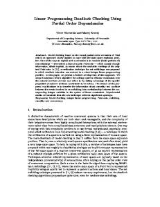
The functionality of the involved functions in the algorithm is straightforward. For instance, secondof returns the second vector of the input list and notemptylists returns false when both lists are empty. Fig. 7(d) describes how the third step of the above algorithm is carried out. There are two side lists, namely: Corr! = (PI' P" ... , P 17 ) and Corr 2 = (P 2, P4 , • • • • P I2 ). The initial directed line segments are IS II = PIP" IS l2 = P,P5 , IS l2 = P,P5 ,ls 21 = Pl P4 • and IS 22 = P4 Po' The first midpoint of the corridor network is node 1 defined as the midpoint of the segment PIPl · During the first iteration of third step, PIP, is found to be active with respect to P2P4 . Thus, the corridor node 2 is created at the midpoint of P,P4 • At this point the side lists Corr l , Corr 2 are stripped off their first vectors and consequently, the assignment of Is II , Is 12 , Is 21 , IS 22 needs to be changed accordingly (i.e., IS I1 = P,P5 • IS 12 = P5 P7 ,ls21 = P4 Po, and IS 22 = PoPx ). P4 Po is the active vector with respect to P,P5 • As before, a new node is established at the midpoint of PoP5 . Note that PoP x is not active over P,P5 • Node 4 is created in a similar fashion. Vector P7 Py is active over PXP IO ' PyP l1 is also active over PXP Ill • Therefore, node 5 is created at the midpoint of P4Py (P4 is the projection of point Py on PXP Ill ). Nodes 6, 7, and 8 are formulated along the same lines. The final node 9 is created at the midpoint of the P I2 P 17 segment. A network of corridor nodes in space is created for each three-dimensional application model. For the four-story building of Fig. 8 we apply the corridor sides algorithm to every story. A typical floor plan is presented in Fig. 9(a). In Fig. 9(b) the various identified corridors are shown with the created midpoints. Fig. lO(a) provides the result of door/exit connection to the network (given in three different pieces for the sake of this presentation). The doors/exits are described by the acronym D"u", (where num is a unique identifier for every door/exit). The corridors of a specific story are unified in Fig. lOeb). There are three possible cases for corridor unification that are given in Fig. 11. In the example of Fig. lO(b), we present all these three cases. In the first, the unification of corridors 2 and 3 (between nodes 122 and 108) takes place. In the second, corridors 1 and 2 are connected over the axis defined by the line segments 150
JOURNAL OF COMPUTING IN CIVIL ENGINEERING
J. Comput. Civ. Eng., 1995, 9(2): 141-156
Corridor2
112 104 Corridor2
117
ri"
08 9
Downloaded from ascelibrary.org by UNIVERSITY OF PITTSBURGH on 03/10/16. Copyright ASCE. For personal use only; all rights reserved.
63 78 1156 .---r-.-I 1..
160
I
OlSl
I I
--"
103_•••••••_ ••••••••••••110
.
0154
129 1241 1311-_ _""'::::.1
085 086 ~li55 Corridorl 1---1 37 r::3:::-2.....,r-,.---.....8 -1-------'9
111
'-------' lbl'······_······_·_··iS7
106
105
(b)
(a)
084 0104
FLOOR4
C rr
50
FLOOR3
Corridor 1: Sidel: 1104 94 811 Side2: 1112 124 1291 Corridor Node.: 1112 113 114)
082 067
I I
~
46
r
1 4
Corridor 2: Sidel: 180 32 99 117 131) Side2: 1131 160 156 169 165 160) Corridor Node.: 1106 107 108 109 110 111)
16
Corridor3
FLOORl
1 3 a
:
114
113
102
COrridor 3: Sidel: 146 63) Side2: 116 50 37 78) Corridor Node.: 1102 103 104 105)
FIG. 8.
FIG. 9.
Sample Four-Floor Construction
8
112
0711 078
D86 DllO
D86
f-
202
37 D84
0104
48
203
0154
204
0155 111
087
088
107
108
18
102
0153
01- D811
so 21
FCA Corridor Network Presentation
Corridor 3
08
114
113
206
Corridor 1
Corridor 2
(
.
)
Corridor 2
Corridor 1 2
2
Corridor 1
0711 078
4
3
3
lOll
112 DllO lOS
D86
168
D8lI
201
0153
203
0154
204
(a)
Corridor 2 Corridor 1
104 D88
122
(b)
113
loa
118
D84
120
1
0104 103 Il67
1111
D82
(b)
2 3
121
(c) 102
FIG. 10.
Three Corridors and Unification Step
FIG. 11. Connections for Networks of Corridor Nodes (Three Cases)
(113,114) and (108,106). Finally, in the third case, the endpoints of corridor 2 are connected by the triplet of nodes (111,107,106). The same process is repeated for the remaining stories. Story networks are connected by the vertical lines that represent building stairways and elevators. In the example at hand. the story floor plans are considered identical and the different story networks are connected by the JOURNAL OF COMPUTING IN CIVIL ENGINEERING
J. Comput. Civ. Eng., 1995, 9(2): 141-156
151
Downloaded from ascelibrary.org by UNIVERSITY OF PITTSBURGH on 03/10/16. Copyright ASCE. For personal use only; all rights reserved.
FIG. 12.
BI
Building Unified Network
-----------::"1
rEJ-=J,:B-=~-l I
L~G B i J·-···--·-··-·--t:···--··-·----·-·jc I
BI 0.16) S (3.14)
A (15,14) F (30,14)
B 0.2)
W 00,9)
B (15,2) B2 (15,0) U (15.1) M (13.1)
Z m~) L m.1) G 00,7) C 00,2)
B2
(al
FIG. 13.
Use of Travel Distance Algorithm
elevators 1 and 2 and the stairways 1 and 2. Fig. 12 presents the unified three-dimensional network of the four story building. The produced network could now be submitted for an extensive fire-code checking. Travel Distance Algorithm
This algorithm calculates the shortest path from every corridor node or door of a given fire zone to the nearest exit (Fig. 13). To achieve that, the algorithm builds a tree that represents all the possible paths (without loops) from every exit to either any corridor node or door of the area under examination. Once the exit paths along with their distances have been computed, they can be stored in the slots of the corresponding frames. These values are to be checked against code imposed regulations during the evaluation phase of the FeA. Algorithm 4: Travel Distance Algorithm
Input: A unified network of corridor nodes (UniNetCorrN). Output: A series of pairs (ExitPath, TraveIDist), where ExitPath is the exit path between a corridor node or door and the nearest exit and TravelDist is the path distance. Algorithm: 1. For every exit E; that belongs in UniNetCorrN repeat all the subsequent steps: 2. Build a tree T E that represents all possible paths (without loops) from the exit E; to any corridor node Carr} (j belongs in the range of corridors that make up the unified network of corridor nodes) or door D k (k is within the range of the doors that are connected to UniNetCorrN). 3. From the generated tree T E ; find the shortest travel distance for every Carr} or D k • 152
JOURNAL OF COMPUTING IN CIVIL ENGINEERING
J. Comput. Civ. Eng., 1995, 9(2): 141-156
Downloaded from ascelibrary.org by UNIVERSITY OF PITTSBURGH on 03/10/16. Copyright ASCE. For personal use only; all rights reserved.
4. Generate the pair (ExitPath,TraveIDist) for every Corri or D k • 5. Store the calculated pair (ExitPath, TravelDist) into the appropriate corridor or door frame. Fig. 13 illustrates the use of this algorithm in the context of the limited floor plan shown in part (a) of the picture. Namely, there are two rooms (Rooml, Room2) with the first having one door and the second two doors. They both are surrounded by corridors as the figure indicates. All the midpoints (E1, S, A etc.) have been already computed (using the previous algorithm) and the list of their coordinates is shown in Fig. 13(a). Fig. 13(b) shows the tree that represents all possible paths without loops from the exit E1 to any possible corridor node or door of the floor plan. During the generation phase of the tree, the distance of every node from the tree root is calculated. As soon as all the paths are found a simple traverse of the tree can determine the shortest travel distance of every midpoint (corresponding to a corridor node) or door from the exit E1. At the end of the tree traverse process, the distance value of every corridor node or door from the exit is input into the corresponding frame slot (one frame of the system is assigned to each corridor node or door). For example, node S should have exit path (S, E1) in its EXIT_PATH slot and the value 2.0 in its TRAVEL_DIS_TO-EXIT slot. The same procedure needs to be repeated for exit E2 of the floor plan that is shown in Fig. 13(a). Exit Signs Algorithm
A great deal of the fire code regulations is given in the placement of exit signs on a floor plan. The exit signs algorithm applies to all cases that an exit or the way to reach it is not immediately visible to the occupants (Lathrop 1985). There should not also exist points in an exit access further than a maximum allowed distance t max to the nearest exit sign. The algorithm receives as input a floor plan described in terms of a polygon (Po), a set of polygons that represent floor rooms and various spaces (e.g., PI' P 2 , . . . , Pn, n > 0), as well as a number of exit signs E{(O ~ I ~ NumofExitSigns). The algorithm determines that every side of the floor plan polygons is visible from at least an exit sign and the distances of its endpoints from the exit signs are less than the maximum travel distance allowed t max • The following lemma is used by the algorithm to decide whether a point of the plane lies outside the region of a polygon P with sides (SOSIS2 ... SI1- ISI1S0)' Its proof is straightforward and it is omitted for brevity. Lemma: If and only if point D is outside of a given polygon P(SOS,S2 ... Sn-,SnSO) then Regionos,,s, ..• 5"5,,
+
Region/)s,.~·,
+
Regionos,s,
+ ... +
Regionos" ,s"
+
Regionos"s" > Regions,,'>',s,
(Fig. 14).
Algorithm 5: Exit Signs Algorithm
Input: Po, the floor plan, a list of n floor polygons: PI, P 2, ... , P" (n > 0), and a list of all the exit signs E{l ~ I ~ NumofExitSigns (NumofExitSigns is the maximum number of exit signs on the floor plan). Output: A list of line segments (LS ii , where i, j are any two locations on the floor plan) that include points that are not visible or that exceed the t max distance from exit signs. Algorithm: ~ i ~ n) decide each rectangular extension Pi (defined by its four coordinates; namely: x min ' Ym;n, x max , Ymax)' 2. For every edge S"", of each polygon P i (l ~ i ~ n) check whether its endpoints SI/I' S" are visible from at least one exit sign. This is carried out using algorithm 1 (which uses the rectangular extensions Pi).
1. For every polygon P;(l
E 3
•
82
(Ij
FIG. 14. Demonstration of Lemma
FIG. 15.
(bj
Use of Exit Signs Algorithm
JOURNAL OF COMPUTING IN CIVIL ENGINEERING
J. Comput. Civ. Eng., 1995, 9(2): 141-156
153
If one or both endpoints S"" S/I is/are visible from at least one exit sign then report the edge S",,, for exit sign violation. • Otherwise, it is required to test whether the edge S"", of the polygon under examination (Pi) is partially hidden from the exit sign E k by another polygon. To identify all potential "obstacles", find all polygon enclosures that overlap with the triangle (ES",S,,). For every "obstacle" polygon determine, using the lemma, whether any of the polygon vertices is internal to the triangle (EkS",S,,). If there exists at least one vertex within the triangle then report the edge S",,, for exit sign violation. If there is no obstacle, check the maximum travel distance between exit E k and the side S"m[max(EkS"" EkS/I)]' If it exceeds the maximum allowed by the fire code (t max ) report the edge S"m for exit sign violation. Downloaded from ascelibrary.org by UNIVERSITY OF PITTSBURGH on 03/10/16. Copyright ASCE. For personal use only; all rights reserved.
•
Consider the floor plan given in Fig. 15(a). During the first step of the second part of the algorithm the visibility of A and B from exit sign E, can be established using the algorithm I. It is necessary to test whether E, is visible from all the points of the edge AB. Even though E 2 is visible from both edge points A and B, there might exist points which cannot see S2 due to "obstacles" (e.g., polygon Po that hides parts of the edge AB from S2)' To locate all potential "obstacles," find all polygon enclosures that overlap with the triangle E,AB (e.g., polygon Po)' If there exists even a single vertex of the polygon Po that falls inside the triangle E,AB (use lemma) E, is not visible from a part of the edge AB. Although the visibility of the line segment CD of polygon P from the E, can be verified by Fig. 15(a), it might be the case that the max(E3 C, E3 D) distance is larger than the distance allowed (max' Fig. 15(b) depicts the same floor plan with two exit signs relocated and one additional sign. Both requirements-visibility and distance-are fulfilled in this floor configuration. j
SUMMARY In this paper we discuss a knowledge-based expert system, the Fire-Code Analyzer. It is evident that manual application of engineering codes on designs is an extremely hard and timeconsuming process. The Fire-Code Analyzer (FCA) reviews Life Safety Code requirements of engineering designs. The system consists of a rule-based system that encapsulates the various code requirements, a frame-based system for building representation, and a set of geometric algorithms. It mainly capitalizes on the flexibility that the frame-based knowledge representation offers. The frame organization proposed here is suitable for processing of three-dimensional objects such as real buildings. At this point of work, the focus of the FCA prototype is on aspects related to means of egress as well as the features of fire protection in a given threedimensional building. We have developed a series of algorithms for eliciting knowledge, including visibility, corridor sides, network of corridor nodes, travel distances, and exit sign algorithm. These algorithms enabled the FCA to review LSC requirements regarding the exit signs, the width of doors and corridors, the way doors swing, the number of required exits, considerations driven for horizontal exits, dead ends, travel distances, and excessive lengths. Once the final report of possible code violations has been compiled, corrective actions can be taken. So far, the FCA prototype has been used to examine architectural layouts from the domain of hospital buildings. In future versions of the system when various types of facilities can be examined by the system, it will be possible to choose the proper provisions requested for the given type of application. It is also expected that an interface with a CAD system will be also available. Until now, particular attention has been paid to avoid duplication of code checking due to code overlapping and to successfully address the issues mentioned in the first section (flexibility, modularity, granularity, etc.). It is worth mentioning that only a fraction of the LSC code has been inserted in our system. We expect that if all requirements are incorporated into the knowledge base, then the volume of the rules is going to affect the system's response time. On the other hand, it is expected that the significant improvements in central processing unit (CPU) processing power and main memory capacity of modern engineering workstations will work beneficially to maintain very satisfactory performance for code-checking expert systems. Some of the points that need further algorithmic refinement or integration and constitute our current and future goals are Floor openings: the enclosures of floor openings such as elevator hoistways and shaftways used for light or ventilation • Smoke barriers: floors separating stories in a building Atriums: the minimum dimension of openings as well as fire resistance of adjacent spaces • Exit discharge and exit passageway: dimensions and adequacy of enclosures • Enclosure and protection: separation and protection of outside stairs in relation to the shape and size of the building 154
JOURNAL OF COMPUTING IN CIVIL ENGINEERING
J. Comput. Civ. Eng., 1995, 9(2): 141-156
Stairs and stair details: dimensions of the stairs Occupant load: adequacy of exit capacity when exits serve more than one floor above and below grade ACKNOWLEDGMENTS We would like to thank Marcela Depiante, Steve Milliner, and the anonymous ASCE reviewers for their comments, which helped us to significantly improve the presentation of the paper. This research was partially supported by the Australian Research Council under Grant NRGS94-18-16-500-05.
Downloaded from ascelibrary.org by UNIVERSITY OF PITTSBURGH on 03/10/16. Copyright ASCE. For personal use only; all rights reserved.
APPENDIX.
REFERENCES "Building requirements for reinforced concrete." (1983). AC/3i8-83. Am. Concrete Inst. (ACI), Detroit, Mich. Barr, A., Feigenbaum, E., and Cohen, P. (1981). The handbook of artificial intelligence. W. Kauffman Inc., San Mateo, Calif. Buis, M., Hammer, J., Hosking, J. G., and Mugridge, W. B. (1987). "An expert advisory system for a fire safety code." Applications ofexpert systems, J. R. Quinland, ed .. Turing Institute Press and Addison-Wesley, Sydney, NSW, Australia. 85-101. Balachandran, M., Roseman, M., and Gero, J. S. (1991). "A knowledge based approach to the automatic verification of designs from CAD databases." Artificial intelligence in design, J. S. Gero, ed., ButterworthHeinemann, Oxford, England, 757-781. Broadbent, G. (1973). Design in architecture: architecture and the human sciences. Wiley Press, London, England. Cronembold, J., and Law, K. (1988). "Automated processing of design standards." 1. Computing in Civ. Engrg., ASCE, 2(3), 255-273. Delis, E. A., and Delis, A. (1991). "Algorithmic support for intelligent fire-code checking." Proc., iEEE into Conf on Tools for Artificial intelligence. Inst. of Electrical and Electronics Engrs.. Inc., New York, N.Y., 291-298. Dym, c., Henchey, R., Delis, E. A., and Gonik, S. (1988). "A knowledge-based system for automated architectural code-checking." Computer-Aided Design, 20(3), 137-145. Eastman, C. (1981). "Recent developments in representation in the science of design." Proc., i8th Design Automation Conf. Inst. of Electrical and Electronics Engrs., Inc., New York, N.Y., 13-21. Fenves, S. (1979). "Recent developments in the methodology for the formulation and organization of design specifications." Engrg. Struct., 1(4),223-229. Fenves, J. S., and Rasdorf, W. J. (1985). "Treatment of engineering design constraints in a relational database." Engrg. with Computers, 1(1). Fikes, R., and Keller. T. (1985). "The role of frame-based representation in reasoning." Communications of the ACM, 28(9), 904-920. First Graphics Inc. (1986). "CAD streamlines design of five project systems." Tech. Rep. Garret, J., and Fenves, S. (1986). "A knowledge based standards processor for structural component design." Tech. Rep. SRS-86-157, Carnegie-Mellon Univ., Pittsburgh, Pa. Gero, J., Radford, A. D., Coyne, R., and Akiner, V. T. (1984). "Knowledge-based computer-aided architectural design." Knowledge engineering in computer-aided design, J. Gero, cd .. North-Holland, Budapest, Hungary, 57-81. Goel, S., and Fenves, S. (1968). "Computer-aided processing of structural design specifications." Dept. of Civ. Engrg. Tech. Rep. SRS-348, Univ. of Illinois, Urbana-Champaign, III. Holtz, N., and Fenves, S. (1980). "Using Design Specifications in Design." Proc-, 2nd ASCE Conf., ASCE, New York, N.Y., 92-101. Howard, H., and Fenves. S. (1983). "Representation and comparison of design specifications." Tech. Rep. SRS83-14i, Dept. ofCiv. Engrg., Carnegie-Mellon Univ., Pittsburgh, Pa. intellicorp; user's manual. (1988). Intellicorp. Lathrop, J. (1985). Life safety code handbook. Nat. Fire Protection Assoc., Boston, Mass. Lopez, A., and Elam, S. (1984). "SICAD: a prototype knowledge based system for conformance checking and design." Tech. Rep., Dept. of Civ. Engrg .. Univ. of Illinois, Urbana-Champaign, Ill. Maher, M. L. (1987). "Expert systems for structural design." 1. Computing in Civ. Engrg., ASCE, 1(4),270283. Maher, M. L., and Fenves, S., (1985). "HI-RISE: a knowledge-based expert system for the preliminary structural design of high rise buildings." Tech. Rep. TR-45-i46, Carnegie-Mellon Univ., Pittsburgh, Pa. Mostow, J. (1985). "Towards better models of the design process." Al Mag., 6(1), 44-57. Nievergelt, J., and Preparata, F. (1982). "Plane-sweep algorithms for intersecting geometric figures." Communications of the ACM, 25(10), 739-746. Niwa, K. (1987). "Use of artificial intelligence confirming compliance to building codes during process of making architectural drawings." Proc-, Int. Conf. and Exhibition of Artificial Intelligence, I. Ohbayashi, ed., Tokyo, Japan, 160-162. Pesquera, c., Hanna, S., and Abel, J. (1984). "Advanced graphical CAD system for 3D steel frames." Proc-, Symp. on Computer-Aided Design in Civ. Engrg., C. Kosten and M. Shephard, eds., ASCE. New York, N.Y., 83-91. Reznikoff, S. C. (1979). Specifications for commercial interiors. Watson-Guptill Pub!., New York, N.Y. Rich, E. (1983). Artificial intelligence. McGraw-Hili Book Co., New York, N.Y. Rosenman, M., and Gero, J. (1985). "An expert system for design codes and design rules." Tech. Rep., Dept. of Arch. Sci., Univ. of Sydney, Sydney, Australia. Sedgewick, R. (1984). Algorithms. Addison-Wesley Pub!. Co., Reading, Mass. Specification for the design and erection of structural steel for huildings. (1978). American Institute of Steel and Construction (AISC), Chicago, Ill. JOURNAL OF COMPUTING IN CIVIL ENGINEERING
J. Comput. Civ. Eng., 1995, 9(2): 141-156
155
Downloaded from ascelibrary.org by UNIVERSITY OF PITTSBURGH on 03/10/16. Copyright ASCE. For personal use only; all rights reserved.
Spoonamore, J., Crowford, K., and Neely, E. (1982). "Computer-aided engineering and architecture." The Military Engr., 74(479), 140-147. Stahl, F., Wright, R., and Fenves, S. (1983). "Expressing standards for computer-aided building design." Computer-Aided Design, 15(6), 329-334. Warren. P. (1984). "Computer-aided design of reinforced concrete." Proc., Symp. in Computer Aided Design in Civ. Engrg., C. Kosten and M. Shephard, eds., ASCE, New York, N.Y., 107-113.
156
JOURNAL OF COMPUTING IN CIVIL ENGINEERING
J. Comput. Civ. Eng., 1995, 9(2): 141-156