sensors Article
Automatic Identification of Subtechniques in Skating-Style Roller Skiing Using Inertial Sensors Yoshihisa Sakurai 1, *, Zenya Fujita 2 and Yusuke Ishige 1 1 2
*
Department of Sports Science, Japan Institute of Sports Sciences, 3-15-1 Nishigeoka, Kita-ku, Tokyo 115-0056, Japan;
[email protected] Faculty of Sport Sciences, Waseda University, 2-579-15 Mikajima, Tokorozawa, Saitama 359-1192, Japan;
[email protected] Correspondence:
[email protected]; Tel.: +81-3-5963-0231
Academic Editor: Vittorio M.N. Passaro Received: 5 February 2016; Accepted: 21 March 2016; Published: 2 April 2016
Abstract: This study aims to develop and validate an automated system for identifying skating-style cross-country subtechniques using inertial sensors. In the first experiment, the performance of a male cross-country skier was used to develop an automated identification system. In the second, eight male and seven female college cross-country skiers participated to validate the developed identification system. Each subject wore inertial sensors on both wrists and both roller skis, and a small video camera on a backpack. All subjects skied through a 3450 m roller ski course using a skating style at their maximum speed. The adopted subtechniques were identified by the automated method based on the data obtained from the sensors, as well as by visual observations from a video recording of the same ski run. The system correctly identified 6418 subtechniques from a total of 6768 cycles, which indicates an accuracy of 94.8%. The precisions of the automatic system for identifying the V1R, V1L, V2R, V2L, V2AR, and V2AL subtechniques were 87.6%, 87.0%, 97.5%, 97.8%, 92.1%, and 92.0%, respectively. Most incorrect identification cases occurred during a subtechnique identification that included a transition and turn event. Identification accuracy can be improved by separately identifying transition and turn events. This system could be used to evaluate each skier’s subtechniques in course conditions. Keywords: cross-country skiing; accelerometer; gyroscope
1. Introduction In skating-style cross-country skiing, based on the course terrain and their skiing velocity, skiers mainly use three subtechniques [1]. In the skating phase, skiers glide on one ski from the push-off movement of the other leg with a V-shaped ski orientation. In the pushing phase, skiers extend their upper extremities and push both poles backward in order to produce the propulsive force. In these subtechniques, skiers perform skating and pushing movements using different timings. The V1 skating technique (V1) is generally considered to be a steep uphill technique and uses an asymmetrical pole push with every second leg push-off. The V2 skating technique (V2) is mainly used on level terrain up to moderate uphill inclines, and is performed with a symmetrical double poling action for each skating push-off. The V2-alternate skating technique (V2A) is used on level terrain with a symmetrical double poling action with every second leg push-off. V1 and V2A have the same number of pole movements and leg push-offs. However, these two movements occur with different timings in the two subtechniques. Some studies have reported the differences of each subtechnique based on physiology and biomechanics. It was found that there is no difference in the heart rate and oxygen cost among subtechniques on flat terrain [2]. Bilodeau et al. [3] compared the skiing velocities and physiological Sensors 2016, 16, 473; doi:10.3390/s16040473
www.mdpi.com/journal/sensors
Sensors 2016, 16, 473
2 of 9
responses of these three subtechniques over a flat, an uphill, and a downhill section, as well as a complete course. The results showed that there is no significant difference in the skiing velocity, estimated oxygen uptake, and average heart rate among these three subtechniques. Similarly, there is no difference among the three subtechniques in the skiing velocity at maximum speed on a flat terrain, although V1 exhibits a higher cycle rate than V2 and V2A. Furthermore, V2 has a longer cycle length than V1 and V2A [1]. In contrast, it has been reported that with an increase in inclination, V2 increasingly requires a higher oxygen cost compared to V1 [4]. In addition, it has been reported that V1 is faster than V2 on a 5.0˝ uphill grade and that the average total cycle force of poles and skis in V1 is higher than that in V2 on a 7–10˝ uphill grade [5]. These data suggest that there are differences in the oxygen cost and exerted force on an uphill terrain. Furthermore, V2A is slower than the other two subtechniques on a 5.0˝ uphill grade when skating at the same intensity [6]. Hence, top-level skiers strategically choose different subtechniques to obtain higher speed and efficiency. Andersson et al. [7] examined subtechnique selection during a simulated sprint time trial. The distributions of V1, V2, and V2A were 31%, 63%, and 6%, respectively. The results showed that sprint skiing performance is primarily related to uphill performance and better utilization of V2. Therefore, it is important to identify subtechniques during skiing to enhance skiers’ performance. In several recent studies, small inertial sensors have been used to analyze cross-country skiing techniques. It has been shown that the subtechniques can be classified visually using the acceleration and angular velocity data from a microsensor located on the upper back [8]. It was found that a difference in hip movements between V1 and V2 can be observed using a tri-axial accelerometer placed on the sacrum [9]. These studies demonstrated the possibility of using inertial sensors to identify subtechniques. A new automatic algorithm has been developed to classify the skating style using a smartphone accelerometer attached to the chest and a machine learning technique [10,11]. However, it is difficult to calculate spatio-temporal variables such as the cycle time, poling time, and recovery time. In some studies, small inertial sensors have been mounted on poles, ski boots, roller skis, and wrists. It has been shown that the acceleration recorded by the pole accelerometer can detect pole hits and lifts, and that recorded by the heel of ski boots can detect ski lifts [12]. Fasel et al. [13] showed that the cycle duration, ski thrust duration, cycle speed, and cycle length of the diagonal stride can be calculated accurately using inertial sensors fixed to the pole and roller ski. Myklebust et al. [12] used the time of pole/ski hits and lifts to classify the subtechniques. However, this method requires many subject-specific thresholds for detecting the timing and the classification of subtechniques. Sakurai et al. [14] identified classical-style subtechniques automatically using inertial sensor data from both the wrists and roller skis. The subtechniques of skating-style cross-country skiing exhibit different arm and ski movement patterns and timings. Therefore, the measurements from arms and skis are considered to be particularly effective in identifying the subtechniques. Furthermore, the use of inertial sensors located on wrists and skis can be analyzed with spatio-temporal analysis for skating-style skiing. Hence, the current study aims to develop an automated subtechnique identification system using inertial sensors. 2. Methods 2.1. Development of an Automated Identification System 2.1.1. Pre-Experiment A pre-experiment was conducted to develop an automated identification system for skating-style subtechniques. A male cross-country skier (age: 22 years; height: 1.75 m; weight: 71.0 kg) participated in this study. The subject provided informed consent prior to the experiment. The subject used his own racing poles and roller skis (MS610C, Marwe Roller Skis, Hyvinkää, Finland) during the test. Four inertial sensors (LP-WS0901, 3-axis accelerometer: ˘50 G; 3-axis gyroscope: ˘1500 ˝ /s, Logical Product Corp., Fukuoka, Japan) were used in this study. The data from the 3-axis accelerometer and gyroscope were synchronously written to the internal memory in each sensor. All sensors were
velocity using all the skating-style subtechniques with the right or left side being dominant (V1R, V1L, V2R, V2L, V2AR, and V2AL) on an asphaltic road. Angular velocities and accelerations were sampled at a rate of 100 Hz and stored by each sensor. The subject was videotaped using a digital video camera (HDR-CX700C, Sony, Tokyo, Japan) to identify the subtechniques employed. Sensors 2016, 16, 473
3 of 9
2.1.2. Definition of One Cycle wirelessly controlled by anprocessed application (SS-WSAP01, Logical Product Fukuoka, Japan). The obtained data were offline using MATLAB R2011aCorp., (The MathWorks, Inc.,The Natick, sensors were worn on the back sides of both wrists of the subject using wrist pouches and were MA, USA). All raw accelerations and angular velocities obtained by the sensors were smoothed using also attached to both his rollerfilter skis. with The test was frequencies conducted atof sub-maximal velocity all the the a Butterworth low-pass digital cutoff 1 and 3 Hz. First, using we defined skating-style subtechniques with the right or left side being dominant (V1R, V1L, V2R, V2L, V2AR, backswing phase of each upper extremity using the 1 Hz low-pass filtered angular velocity of the and V2AL) on an asphaltic road. Angular velocities and accelerations were sampled at a rate of 100 Hz forearms corresponding to the mediolateral axis. Pole contact was defined as the local maximum and stored by each sensor. The subject was videotaped using a digital video camera (HDR-CX700C, point during each backswing phase—which had the largest amount of change between the local Sony, Tokyo, Japan) to identify the subtechniques employed.
maximum and the previous local minimum of the raw forearm acceleration, whose axis was parallel 2.1.2. Definition of One Cycle to the pole at the instant of contact. When the contact point was less than 0.250 s apart from the previousThe one,obtained the onedata thatwere exhibited lower raw using acceleration at R2011a each contact point was eliminated. processed offline MATLAB (The MathWorks, Inc., Natick, The contact of both arms was defined as the contact whose difference between the right and leftusing contacts MA, USA). All raw accelerations and angular velocities obtained by the sensors were smoothed was aless than 0.025low-pass s. The other contacts were defined as the right or left contact. Thedefined contactthe points Butterworth digital filter with cutoff frequencies of 1 and 3 Hz. First, we werebackswing used as the startofand points of oneusing cycle.the 1 Hz low-pass filtered angular velocity of the phase eachend upper extremity forearms corresponding to the mediolateral axis. Pole contact was defined as the local maximum point each backswing phase—which 2.1.3.during Definition of Recovery Motion had the largest amount of change between the local maximum and the previous local minimum of the raw forearm acceleration, whose axis was parallel to the pole atThe the roller instantski of contact. When the contact point was less than 0.250 s apart from the previous one, the shows the internal tilt for edging during the push-off movement. Subsequently, one that exhibited lower raw acceleration at each contact point was eliminated. The contact of both was the roller ski rolls outward during the recovery phase (Figures 1–3). Thus, any recovery motion arms was defined as the contact whose difference between the right and left contacts was less than identified using the 3 Hz low-pass-filtered roll angular velocity of the roller skis. The recovery motion 0.025 s. The other contacts were defined as the right or left contact. The contact points were used as was defined as the roll angular velocity of the roller ski with a maximum value of over 25 × pitch /s. the start and end points of one cycle.
This threshold was determined empirically.
(a)
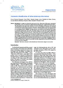
(b) Figure 1. Angular velocities ofofforearms sagittalplane plane(forward (forward swing/backswing) Figure 1. Angular velocities forearms in in the the sagittal swing/backswing) and and roll roll angular velocities of of roller skis twocycles cyclesofofthethe skating technique: angular velocities roller skis(inward/outward) (inward/outward) during during two V1V1 skating technique: (a) V1R; V1L. Angular velocitieswere were filtered filtered with filter. TheThe vertical blackblack line line (a) V1R; (b) (b) V1L. Angular velocities withaa33Hz Hzlow-pass low-pass filter. vertical indicates the start of the second cycle. indicates the start of the second cycle.
Sensors 2016, 16, 473
4 of 9
2.1.3. Definition of Recovery Motion The roller ski shows the internal tilt for edging during the push-off movement. Subsequently, the roller ski rolls outward during the recovery phase (Figures 1–3). Thus, any recovery motion was identified using the 3 Hz low-pass-filtered roll angular velocity of the roller skis. The recovery motion was defined as the roll angular velocity of the roller ski with a maximum value of over 25 ˆ pitch ˝ /s. This was determined empirically. Sensorsthreshold 2016, 16, 473 4 of 9 4 of 9
Sensors 2016, 16, 473
Figure 2. 2. Angular velocities velocities of forearms forearms in the the sagittal plane plane (forward swing/backswing) swing/backswing) and roll roll Figure Figure 2. Angular Angular velocities of of forearms in in the sagittal sagittal plane(forward (forward swing/backswing) and and roll angular velocities of roller skis (inward/outward) during two cycles of successive use of the V2R and angular velocities of roller skis (inward/outward) during two cycles of successive use of the V2R and angular velocities of roller skis (inward/outward) during two cycles of successive use of the V2R and V2L skating skating techniques. techniques. Angular Angular velocities velocities were were filtered filtered with with aa 33 Hz V2L Hz low-pass low-pass filter. filter. The The vertical vertical black black V2L skating techniques. Angular velocities were filtered with a 3 Hz low-pass filter. The vertical black lines indicate indicate the the start start of of each each cycle. cycle. lines lines indicate the start of each cycle.
(a) (a)
(b) (b) Figure 3. Angular velocities of forearms in the sagittal plane (forward swing/backswing) and roll Figure 3. Angular Angular velocities velocities of of forearms forearms in in the the sagittal sagittal plane plane (forwardswing/backswing) swing/backswing) and roll roll Figure angular3.velocities of roller skis (inward/outward) during two (forward cycles of the use of the V2A and skating angular velocities of roller skis (inward/outward) during two cycles of the use of the V2A skating angular velocities of roller skis (inward/outward) two cycles uselow-pass of the V2A skating technique: (a) V2AR; (b) V2AL. Angular velocitiesduring were filtered withofathe 3 Hz filter. The technique: (a) (a)V2AR; V2AR;(b) (b) V2AL. Angular velocities were filtered with a low-pass 3 Hz low-pass filter. The technique: V2AL. Angular velocities were filtered with a 3 Hz filter. The vertical vertical black line indicates the start of the second cycle. vertical black line indicates the start of the second cycle. black line indicates the start of the second cycle.
2.1.4. Detection of Main Subtechniques 2.1.4. Detection of Main Subtechniques The decision tree for the classification of main subtechniques has five decision nodes and six The decision tree for the classification of main subtechniques has five decision nodes and six leaves, as illustrated in Figure 4. V2 has only one recovery motion of the right or left roller ski during leaves, as illustrated in Figure 4. V2 has only one recovery motion of the right or left roller ski during the arm’s forward swing phase (Figure 2) whereas V1 and V2A have two recovery motions the arm’s forward swing phase (Figure 2) whereas V1 and V2A have two recovery motions (Figures 1 and 3). Therefore, V2 was defined by Rule 1, i.e., by the number of recovery motions. V2R (Figures 1 and 3). Therefore, V2 was defined by Rule 1, i.e., by the number of recovery motions. V2R was defined as one recovery motion with the right roller ski and V2L with the left roller ski by
55ofof99
Sensors2016, 2016,16, 16,473 473 Sensors
V1L and V2AR have recovery motions in the order of left and right (Figures 1b and 3a). Therefore, 2.1.4. Detection of Main Subtechniques V1 and V2A were divided into two groups based on the first side of the recovery motion (Rule 3 in Figure 4). After pole contact, recovered weaker side’s rollerhas skifive during the arm’s backswing The decision tree for theskiers classification ofthe main subtechniques decision nodes and six motion, and there was a strong side roller ski pushing and recovery phase during the arm’s leaves, as illustrated in Figure 4. V2 has only one recovery motion of the right or left roller skiforward during swing motion in V1 (Figure 1). On the other hand, the skiers recovered the roller ski after the pole the arm’s forward swing phase (Figure 2) whereas V1 and V2A have two recovery motions (Figures 1 push-off in V2A (Figure 3). Therefore, V1 and V2A were distinguished using the sign of the 1 Hz and 3). Therefore, V2 was defined by Rule 1, i.e., by the number of recovery motions. V2R was defined low-pass-filtered forearm angular velocity to the at the of the the as one recovery motion with the right rollercorresponding ski and V2L with themediolateral left roller skiaxis by Rule 2, time i.e., by first of local maximummotion of the(Figure roll angular velocity of the roller ski; positive and negative values are side the recovery 4). classified as V2A and V1, respectively (Rule 4 in Figure 4).
Figure Figure4.4. Decision Decision tree treefor forthe theclassification classificationmain mainsubtechniques. subtechniques.
2.1.5.Figures Exceptions 1 and 3 show the angular velocities of the forearms and roller skis during V1 and V2A, respectively. andtwo V2Asubtechniques have both right and the left above recovery motions and similar angular velocity There areV1 other besides three major subtechniques in skating-style histories. V1R and V2AL recovery motions from in theaorder of right and (Figures andhas 3b);a cross-country skiing. Thehave firstthe one is a transition subtechnique to left another one1a that V1L and V2AR have recovery motions in the order of left and right (Figures 1b and 3a). Therefore, different movement pattern compared to the major subtechniques. The other one is a turn during a V1 and Therefore, V2A were adivided into two groups based the first side of the recovery motionand (Rule 3 inIf curve. new subtechnique, “V4,” was on introduced to represent the transition turn. Figure 4). After pole contact, skiers recovered the weaker side’s roller ski during the arm’s backswing the identified subtechniques were a sequence needed to perform the transition (e.g., before or after motion, and there was a strong rollerand ski usually pushingdid and recovery during the arm’s V1R is the subtechnique, exceptside for V1R) not performphase it (e.g., continuous V2Rforward or V2L), swing motion in V1 (Figure On thewas other hand, the skiers recovered ski after the pole the first subtechnique of the 1). sequence changed to V4. Table 1 showsthe theroller exception procedure of push-off in V2A (Figure 3). Therefore, V1 and V2A were distinguished using the sign of the 1 Hz the sequences. Row A shows the first subtechnique of the sequence, Row B shows the subtechniques low-pass-filtered forearm angular velocity corresponding tothe the subtechniques mediolateral axis at require the timeaof the first that can follow the first subtechnique, and Row C shows that transition local of the roll angular velocity of the roller ski; positive and negative values are classified aftermaximum the first subtechnique. as V2A and V1, respectively (Rule 4 in Figure 4). Table 1. Sequence of each main subtechnique. Row A comprises the first subtechnique of the sequence,
2.1.5. Row Exceptions B the subtechniques that can follow the first one, and Row C the subtechniques that require a
transition first one. There are after otherthe two subtechniques besides the above three major subtechniques in skating-style cross-country skiing. The first one is a transition A Bfrom a subtechnique to another C one that has a different movement pattern compared to the major subtechniques. The other one isV2AR, a turnV2AL during a curve. V1R V1R V1L, V2R, V2L, Therefore, a new subtechnique, “V4,” was introduced to represent the transition and V1L V1L V1R, V2R, V2L, V2AR, V2ALturn. If the identified subtechniques were a sequence needed to perform the V1R, transition V2R V2L, V2AL V1L, (e.g., V2R, before V2AR or after V1R is the subtechnique, except did not perform V1R, it (e.g., continuous V2R or V2L), the V2L for V1R) and usually V2R, V2AR V1L, V2L, V2AL first subtechnique ofV2AR the sequence was changed to V4. Table 1 shows the exception procedure of the V2L, V2AR V1R, V1L, V2L, V2AL sequences. Row A shows the first subtechnique of the sequence, Row B shows the subtechniques that V2AL V2R, V2AL V1R, V1L, V2R, V2AR can follow the first subtechnique, and Row C shows the subtechniques that require a transition after the first subtechnique.
Sensors 2016, 16, 473
6 of 9
Table 1. Sequence of each main subtechnique. Row A comprises the first subtechnique of the sequence, Row B the subtechniques that can follow the first one, and Row C the subtechniques that require a transition after the first one. A V1R V1L V2R V2L V2AR V2AL
B
C
V1R V1L V2L, V2AL V2R, V2AR V2L, V2AR V2R, V2AL
V1L, V2R, V2L, V2AR, V2AL V1R, V2R, V2L, V2AR, V2AL V1R, V1L, V2R, V2AR V1R, V1L, V2L, V2AL V1R, V1L, V2L, V2AL V1R, V1L, V2R, V2AR
2.2. Validation Experiment Sensors 2016, 16, 473 2.2.1. Subjects
6 of 9
Eleven collegeExperiment cross-country skiers (seven females and four males) and four male college 2.2. Validation Nordic combined skiers belonging to the Ski Association of Japan participated in this study. The 2.2.1. Subjects anthropometric and physical performance characteristics of the subjects are presented in Table 2. cross-country skiers (seven females and four males) and fourperformance. male college Nordic The subjectsEleven had college no known disorders that would influence their skiing Before the combined skiers belonging to the Ski Association of Japan participated in this study. The experiment, the purpose and procedures of this study were explained to each subject, and written anthropometric and physical performance characteristics of the subjects are presented in Table 2. The informed consents were obtained from all of them. The experimental procedure was approved by the subjects had no known disorders that would influence their skiing performance. Before the Ethical Committee of purpose the Japan of Sports Sciences. experiment, the andInstitute procedures of this study were explained to each subject, and written informed consents were obtained from all of them. The experimental procedure was approved by the
Table 2. Anthropometric and physical performance characteristics of the subjects. The data are shown Ethical Committee of the Japan Institute of Sports Sciences. as “means (standard deviation)”. Table 2. Anthropometric and physical performance characteristics of the subjects. The data are shown as “means (standard deviation)”. Cross-Country Nordic Combined
Age (years)
Age Height (years)(m) Weight Height (m)(kg) VO2max (mL/min/kg) Weight (kg) VO2max (mL/min/kg)
Male Cross-Country (n = 4) Female (n = 7) Male (n19.0 = 4)(2.0) Female (n(1.5) = 7) 20.1 1.78 (0.02) 1.60 (0.05) 19.0 (2.0) 20.1 (1.5) 71.2 (2.6) (3.4) 1.78 (0.02) 1.6052.7 (0.05) 69.9 (1.7) 57.3 (6.1) 71.2 (2.6) 52.7 (3.4) 69.9 (1.7) 57.3 (6.1)
MaleCombined (n = 4) Nordic Male = 4) 19.5 (n (1.3) 1.72 19.5(0.02) (1.3) 64.3(0.02) (2.7) 1.72 63.3 (3.7) 64.3 (2.7) 63.3 (3.7)
2.2.2. Protocol 2.2.2. Protocol
In the experiments, all subjects used their own racing poles and racing roller skis (MS610C, Marwe the experiments, all subjects used their own racing poles and racing roller skis (MS610C, Roller Skis, In Hyvinkää, Finland). As in the pre-experiment, four sensors were attached: two on the Marwe Roller Skis, Hyvinkää, Finland). As in the pre-experiment, four sensors were attached: two wrists and two on the roller skis of the subjects. The rollers of the subjects and the movements of the on the wrists and two on the roller skis of the subjects. The rollers of the subjects and the movements pole tipsofwere recorded a compact digital video camera (HDR-AS15, Sony the pole tips wereusing recorded using a compact digital video camera (HDR-AS15, SonyInc., Inc.,Tokyo, Tokyo, Japan). The camera was fixed with a fixed downward inclination to the left shoulder strapstrap of a tight-fitting backpack Japan). The camera was with a downward inclination to the left shoulder of a tight-fitting (Figure 5). All subjects skied through a 3450 m undulating ski course using skating style at (Figure backpack 5). All subjects skied through a 3450 m undulating roller roller ski course using thetheskating style at their maximum speed. their maximum speed.
Figure 5. Locations of inertial sensors wrists and and in thethe bindings of roller skis. Askis. videoA video Figure 5. Locations of inertial sensors ononwrists infront frontofof bindings of roller is located onleft the shoulder left shoulder strap. camera camera is located on the strap.
2.2.3. Data Analysis Subtechniques were detected using an automatic identification system that was developed based on the pre-experiment results. The actual subtechniques used were determined from the video using the movements of the poles and the roller skis. This check was carried out visually by one of the authors who was a past ski racer and is a present coach with 18 years of cross-country skiing
Sensors 2016, 16, 473
7 of 9
2.2.3. Data Analysis Subtechniques were detected using an automatic identification system that was developed based on the pre-experiment results. The actual subtechniques used were determined from the video using the movements of the poles and the roller skis. This check was carried out visually by one of the authors who was a past ski racer and is a present coach with 18 years of cross-country skiing experience. The total number of cycles and the number of cycles of each subtechnique were calculated using both the automatic and visual methods. These results were presented in the form of a confusion matrix. 3. Results Table 3 shows the confusion matrix of the subtechniques obtained using the automatic and visual methods. A total of 6768 cycles (range: 385–525) subtechniques, including 127 V1R (range: 0–51), 41 V1L (range: 0–22), 1950 V2R (range: 99–200), 1955 V2L (range: 93–202), 805 V2AR (range: 0–113), 631 V2AL (range: 0–167), and 1259 V4 (range: 63–102), were identified using the visual method. A breakdown of 1259 V4 by the visual method was 66 “transition” (range: 1–9) and 1193 “turn” (range: 54–101). The subtechniques identified using the visual method were assumed to be correct and were used as a gold standard. The numbers of each subtechnique correctly identified by automatic identification were 120, 40, 1920, 1932, 767, 587, and 1047 for V1R, V1L, V2R, V2L, V2AR, V2AL, and V4, respectively. The accuracy of automatic identification for all subtechniques for all subjects was 94.7% ˘ 3.0% (89.0–98.3%). The identification precision for V1R, V1L, V2R, V2L, V2AR, V2AL, and V4 were 87.6%, 87.0%, 97.5%, 97.8%, 92.1%, 92.0%, and 91.7%, respectively. V4, whose recall was 83.2%, was the most incorrectly identified subtechnique. Table 3. Confusion matrix for subtechniques using automatic identification versus a visual check. Automatic Identification
Visual check
V1R V1L V2R V2L V2AR V2AL V4 Total Precision (%)
V1R
V1L
V2R
V2L
V2AR
120 0 0 0 0 0 17 137 87.6
1 40 0 0 0 0 5 46 87.0
1 0 1920 0 7 3 39 1970 97.5
0 0 1 1932 0 15 27 1975 97.8
3 0 0 3 767 1 59 833 92.1
V2AL V4
Total
Accuracy (%)
0 0 7 0 0 587 44 638 92.0
127 41 1950 1955 805 631 1259
94.5 97.6 98.5 98.8 95.3 93.0 83.2
2 1 20 20 31 21 1047 1142 91.7
4. Discussion The automatic identification method for skating-style subtechniques correctly identified 6413 subtechnique cycles out of a total of 6768 cycles, which indicates an accuracy of 94.8%. This result implies that it is possible to identify the skating-style subtechniques used by many cross-country skiers using the proposed automatic identification method. However, there were a total of 355 incorrect identifications, 54% of which occurred during V4 identification. In addition, 27% of them identified the main subtechniques as V4. The most common incorrect identification among the main subtechniques was between V2 and V2A. There is a difference in the number of recovery motions between the two subtechniques. V2 has only one recovery motion and V2A has right and left recovery motions during one cycle. Therefore, identification accuracy can be improved by modifying the definition of the recovery motion. In this study, V4 was defined as “transition” and “turn” because it is impossible to distinguish these events from only inertial sensor data in cross-country circuit skiing. Therefore, the automatic identification did not classify V4 directly and determined it via the exception procedure. The 5.2% and 94.8% of V4 by the visual method were “transition” and “turn”, respectively. Therefore, the correct identification of “turn” is important to improve the accuracy of this method. As for the transition,
Sensors 2016, 16, 473
8 of 9
the degree of correct identification was negatively correlated to the number of transitions between subtechniques [11]. Therefore, the correct identification of “transition” will also improve the accuracy of this method. As shown in Table 2, there are 26 possible transition patterns from one subtechnique to another. Therefore, if the sensor data were available for all transitions, it may be possible to produce an identification system using signal processing or machine learning [10,11]. On the other hand, a skier generally uses a stepping action during V1, V2, or V2A to change the skiing direction during a turn. Therefore, the time histories of the inertial sensors were similar to those of the main subtechniques. Furthermore, there are many possible turning styles that can be produced by changing the step timing and number of steps. Therefore, it would be impossible to classify a turn by using sensor data only. A global navigation satellite system (GNSS) or a global positioning system (GPS) has been used to measure the skiers’ position and velocity during cross-country skiing [7,15–17]. GNSS/GPS can measure a skier’s position, which would reveal whether he/she skies on the straight section or a corner using a course map. Skiers hardly use a turn in a straight section in skating-style skiing. Hence, V4 in the straight section would be a transition and that in a corner would be a turn, as identified using GNSS/GPS measurements. Nonetheless, some skiers use transitions and turns in succession. Further studies are needed to detect transitions and turns in both laboratory and field conditions. In this method, the pole contacts were detected, which can be used to calculate the cycle time. Furthermore, pole lift was detected using the norm pole acceleration [13]. The poling time and recovery time can be calculated using pole contact and lift [12,13]. Furthermore, the inertial sensor on the roller ski could detect ski contact and leave. These parameters are useful for spatio-temporal analysis of each subtechnique. In addition, it should be possible to use sensor data to evaluate left/right side symmetry/asymmetry in each subtechnique. The accurate identification of subtechniques is a gateway to analyze a skier’s performance in a course condition. The identified subtechniques with GNSS/GPS data could analyze what subtechniques were used at a particular position and inclination of the course, the distribution of the main subtechniques, the skiing velocity in each subtechnique, and the comparison of subtechnique selection in each lap [7]. Furthermore, the subtechnique distributions as a function of the inclination and skiing velocity from the combination of subtechnique detection and GNSS/GPS data has been used to analyze the technical characteristics of skiers [14,15]. This information would assist the evaluation of subtechnique selection and the strong and weak subtechniques of a skier. Therefore, the combination of inertial sensors and GNSS/GPS would be useful for analyzing each skier’s subtechniques. 5. Conclusions An automated identification system using data from four inertial sensors mounted on both wrists and roller skis successfully classified the skating-style subtechniques correctly. However, identification accuracy can be improved by separately identifying transitions and turns. Further analysis of arm and ski movements can provide spatio-temporal analysis and symmetry/asymmetry evaluation of each subtechnique. In addition, the use of GNSS/GPS can provide information regarding the skiing velocity, position, and gradient of the terrain. This information and the detected subtechnique can help in analyzing a skier’s performance in course conditions such as subtechnique selection and evaluation of each subtechnique. Acknowledgments: This study was supported by the Koduki Foundation. Author Contributions: All authors have contributed to the study design and experiment. Yoshihisa Sakurai and Zenya Fujita conducted the analysis and manuscript writing. Yusuke Ishige provided helpful feedback on the comments on the manuscript. Conflicts of Interest: The authors declare no conflict of interest.
Sensors 2016, 16, 473
9 of 9
References 1. 2. 3. 4. 5. 6. 7.
8.
9. 10.
11.
12.
13.
14. 15.
16. 17.
Nilsson, J.; Tveit, P.; Eikrehagen, O. Effects of speed on temporal patterns in classical style and freestyle cross-country skiing. Sports Biomech. 2004, 3, 85–108. [CrossRef] [PubMed] Millet, G.P.; Boissere, D.; Candau, R. Energy cost of different skating techniques in cross-country skiing. J. Sports Sci. 2003, 21, 3–11. [CrossRef] [PubMed] Bilodeau, B.; Roy, B.; Boulay, M.R. A comparison of three skating techniques and the diagonal stride on heart rate responses and speed in cross-country skiing. Int. J. Sports Med. 1991, 12, 71–76. [CrossRef] [PubMed] Kvamme, B.; Jakobsen, V.; Hetland, S.; Smith, G. Ski skating technique and physiological responses across slopes and speeds. Eur. J. Appl. Physiol. 2005, 95, 205–212. [CrossRef] [PubMed] Stöggl, T.; Kampel, W.; Müller, E.; Lindinger, S. Double-push skating versus V2 and V1 skating on uphill terrain in cross-country skiing. Med. Sci. Sports Exerc. 2010, 42, 187–196. [CrossRef] [PubMed] Bilodeau, B.; Boulay, M.R.; Roy, B. Propulsive and gliding phases in four cross-country skiing techniques. Med. Sci. Sports Exerc. 1992, 24, 917–925. [CrossRef] [PubMed] Andersson, E.; Supej, M.; Sandbakk, O.; Sperlich, B.; Stöggl, T.; Holmberg, H.C. Analysis of sprint cross-country skiing using a differential global navigation satellite system. Eur. J. Appl. Physiol. 2010, 110, 585–595. [CrossRef] [PubMed] Marsland, F.; Lyons, K.; Anson, J.; Waddington, G.; Macintosh, C.; Chapman, D. Identification of cross-country skiing movement patterns using micro-sensors. Sensors 2012, 12, 5047–5066. [CrossRef] [PubMed] Myklebust, H.; Losnegard, T.; Hallen, J. Differences in V1 and V2 ski skating techniques described by accelerometers. Scand. J. Med. Sci. Sports 2013, 24, 882–893. [CrossRef] [PubMed] Holst, A.; Jonasson, A. Classification of movement patterns in skiing. In Twelfth Scandinavian Conference on Artificial Intelligence: SCAI 2013; Jaeger, M., Lielsen, T.D., Viappiani, P., Eds.; IOS Press BV: Amsterdam, Holland, 2013; pp. 115–124. Stöggl, T.; Holst, A.; Jonasson, A.; Andersson, E.; Wunsch, T.; Norström, C.; Holmberg, H.C. Automatic classification of the sub-techniques (gears) used in cross-country ski skating employing a mobile phone. Sensors 2014, 14, 20589–20601. [CrossRef] [PubMed] Myklebust, H.; Nunes, N.; Hallén, J.; Gamboa, H. Morphological analysis of acceleration signals in cross-country skiing—Information extraction and technique transitions detection. In Proceedings of the Biosignals—International Conference on Bio-Inspired Systems and Singal Processing (BIOSTEC 2011), Rome, Italy, 26–29 January 2011. Fasel, B.; Favre, J.; Chardonnens, J.; Gremion, G.; Aminian, K. An inertial sensor-based system for spatio-temporal analysis in classic cross-country skiing diagonal technique. J. Biomech. 2015, 48, 3199–3205. [CrossRef] [PubMed] Sakurai, Y.; Fujita, Z.; Ishige, Y. Automated identification and evaluation of subtechniques in classical-style roller skiing. J. Sports Sci. Med. 2014, 13, 651–657. [PubMed] Bortolan, L.; Pellegrini, B.; Impellizzeri, F.; Schena, F.; Muller, E.; Lindinger, S.; Stöggl, T. Automatic detection of technique during on snow cross-country skiing. In Science and Skiing V; Muller, E., Lindinger, S., Stöggl, T., Eds.; Meyer & Meyer Sport: Tyrol, Austria, 2012; pp. 483–491. Sandbakk, S.B.; Supej, M.; Sandbakk, Ø.; Holmberg, H.C. Downhill turn techniques and associated physical characteristics in cross-country skiers. Scand. J. Med. Sci. Sports 2014, 24, 708–716. [CrossRef] [PubMed] Sandbakk, Ø.; Sandbakk, S.B.; Supej, M.; Holmberg, H.C. The velocity and energy profiles of elite cross-country skiers executing downhill turns with different radii. Int. J. Sports Physiol. Perform. 2014, 9, 41–47. [CrossRef] [PubMed] © 2016 by the authors; licensee MDPI, Basel, Switzerland. This article is an open access article distributed under the terms and conditions of the Creative Commons by Attribution (CC-BY) license (http://creativecommons.org/licenses/by/4.0/).