Automatic Translation of SysML Models to SystemC Executable Specification Keyla Guimarães Macharet Brasil
Diógenes Cecilio da Silva Junior
Departamento de Engenharia Elétrica Universidade Federal de Minas Gerais Belo Horizonte, MG - Brasil
Departamento de Engenharia Elétrica Universidade Federal de Minas Gerais Belo Horizonte, MG - Brasil
[email protected]
ABSTRACT System designs become critical as implementation technology progress toward complex integrated circuits and timeto-market pressure continues to grow. There is a strong necessity to develop methodologies to reduce cost and time spent during all the design phases and system development. In this paper a methodology for the automatic translation of SysML diagrams to a SystemC executable specification is proposed and demonstration of usage is shown through a case study. The proposed approach has some advantages, such as: smaller cost due to project changes, easier documentation and better understanding of the project by stakeholders.
General Terms Embedded Systems, SoC design
Keywords Unified Modeling Language, SysML, SystemC
1.
INTRODUCTION
There is a growing demand for smaller and more complex embedded systems leading to increased design complexity. The actual goal of embedded system design is to balance production cost, development time and functionality considerations[4]. The combination of new methodologies - such as model driven architecture - and languages - such as SystemC - is an approach to manage the increasing system complexity. The proposed methodology will have advantages, such as: smaller cost due to project changes, reduction of time spent during system design phases and reuse of developed code. SysML is a modeling language based on UML. SystemC is a language with C++-like syntax that enables the description of concurrent systems in an event-based way. These two languages are typically used in the context of embedded software development. SystemC is able to describe systems
[email protected]
from the executable specification level down to the RT level. SystemC can be used to design complex, embedded HW/SW systems and supports some techniques to face complexity of modern designs such as abstraction, project and design reuse[1]. In our laboratory there is an effort to develop a system to translate SysML description into SystemC code. The aim of this paper is to present a translation of two SysML structure diagrams - Internal Block Diagram and Block Definition Diagram - and one behavior diagram - State Machine Diagram - to SystemC. The Sequence Diagram is the object of another master’s degree project. On the next subsection it is provided a small overview on SysML modeling language. The rest of the paper is organized as follows: section 2 is dedicated to related works concerning the synthesis of UML and SysML models to SystemC code. In section 3 is presented the translation methodology based on XSLT stylesheets for automatic SystemC code generation from SysML and a usage example can be found on section 4.
1.1
SysML
The Systems Modeling Language (SysML) is the result of the International Council on Systems Engineering initiative to customize UML as a general-purpose modeling language for systems engineering applications. After joining the Object Management Group (OMG), which maintains the UML specification, in 2004 was distributed the first SysML specification draft. SysML reuses four UML diagrams: Sequence Diagram, State Machine, Use Case Diagram and Package Diagram. The language modified three diagrams: Activity Diagram, Block Definition Diagram (modification of UML Class Diagram) and Internal Block Diagram (modification of UML Composite Structure Diagram). SysML also adds two new diagrams: Requirement Diagram and Parametric Diagram.
1.1.1
Internal Block Diagram
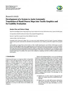
The internal block diagram is used to describe the internal structure of a block, its properties and connectors, and how its parts are interconnected. We can see an example of this diagram at the center block in the figure 1.
1.1.2
Block Definition Diagram
The block definition diagram is used to define block characteristics in terms of their structural and behavioral features, and the relationships between the blocks such as their hierarchical relationship. An example of a Block Definition Diagram can been seen in Figure 1 and is composed of three blocks (Driver, Calculator and Monitor ) and each block may have flow ports with different directions (in and out).
3.
METHODOLOGY
The goal is to allow structure and behavior modeling and generate a SystemC executable specification. The transformation methodology used to generate SystemC from SysML diagrams is described over the next few subsections. Each step will be explained in order, with emphasis on steps three and five - the most important ones.
3.1
Step 1: Design SysML Diagrams
The designer model SysML diagrams using the Altova UModel tool[11]. Altova UModel is a graphical tool that captures SysML diagrams and has plugins to generate C/C++ code. A plugin to generate SystemC code was developed and is currently integrated into Altova UModel. The designer should use the SysML structure diagrams - Internal Block Diagram and Block Definition Diagram - and the State Machine Diagram, for behavior description. Ports can use types already provided by UModel tool or can configure SystemC primitive types to use in their own project. Figure 1: Block Definition Diagram Calculator
1.1.3
State Machine Diagrams
The state machine diagram models the behavior of a system by describing the various states an object may be in, and the transitions between the states. The tool translates the diagram to SystemC code and associate it to a block operation.
2.
RELATED WORKS
One of the first attempts on using UML in the design of System on Chips (SoCs) dates back to 2004 [7], and presented some benefits of combining UML models and SystemC for system documentation and specification. Riccobene[10] presented a UML 2.0 profile of the SystemC language exploiting the model-driven architecture capabilities of defining modeling languages, platform independent and reducible to platform dependent languages. A similar approach was presented by [12]. In [2] we find an approach to generate SystemC code automatically at early stages of SoC design from UML sequence and activity diagrams. From the initial attempts an UML profile specific to system modeling (SysML - Systems Modeling Language) was created as an official OMG standard in July of 2006[5]. During the next year, a few works on mapping SysML to SystemC, generating automatic executable were presented, code such as [9] and [8]. Raslan[9] describes an approach to translate SysML structure and behavior diagrams but does not show an example of the SystemC code generated. Prevostini[8] translates Internal Block Diagrams and Block Definition Diagrams just to create the structure of modules and uses the Activity Diagram to allocate operations to blocks. This work presents an approach based on SysML structure diagrams and State Machine behavior diagram, and will generate a SystemC executable specification. SystemC modules are generated with their ports and processes. The approach uses State Machine diagrams to describe control-oriented processes, associates them to block operations and automatically generates SystemC code. The tool also generates the main SystemC file and the sc main() function with the instantiation of the top-level SystemC modules, channels to connect them along with the ports to channels bindings.
3.2
Step 2: Export SysML as XMI File
This step is performed by the Altova modeling tool. The designer will export the SysML diagrams as a XML-based Metadata Interchange (XMI) file. XMI is an interchange format for metadata defined in terms of the MOF standard[6]. In addition to supporting the exchange of complete models, XMI supports the exchange of models in differential form. It is a textual repository with the complete SoC description.
3.3
Step 3: Import XMI to SysMLToSystemC
This step and next ones are performed by the SysMLToSystemC translation tool. The XMI representation of a SysML model has a lot of details that relate to graphical representation of elements, references among different diagrams, and more information. Since this file is generated according to the MOF metamodel structure, the information associated with the elements is not easily accessible. Therefore, this format was not the ideal to start the code generation. Then, a choice was made to process the XMI file to extract only the relevant data and details needed by the next steps. With all data, a C# model of classes capable of describing the SoC is created. This group of classes are responsible for describing blocks, ports and operations.
3.4
Step 4: Choose Generation Options
During this step it is possible to associate block operations with existing State Machine Diagrams or existing source code from external files, in order to use the SystemC code generated from them inside the operation. We can see how this step is performed by the user in Figure 2. These informations will be used during the generation of the SystemC code.
3.5
Step 5: Generate SystemC Executable Specification
Using the information now described as C# classes and the relation between existing state machine diagrams and blocks operations, an XML file is generated as an intermediary step to generate the source code. This allows for an easy data parsing by subsequent algorithms and easier data exchange with other tools. To generate the XML file, the algorithm
Figure 3: SysML State Machine Diagram Example Figure 2: Selecting generation options retrieves all instances of classes, the associations between them, and output all the information as an XML document. This intermediate XML file can be easily transformed into SystemC code with a template file. The technology chosen to perform this step is the W3C XSLT (Extensible Stylesheet Language Transformations)[3], which transforms XML file documents based on stylesheets. The tool will transform the new XML created into a SystemC executable specification, using a different XSLT stylesheet for each type of file (.h,.cpp). During this step the basic mapping between SysML and SystemC entities are: Figure 4: Add Source Code Screen
• SysML Blocks Õ SystemC Modules • SysML Flow Ports Õ SystemC Ports • SysML Operations Õ SystemC Processes
4.
s c f i f o i n < int > a ; s c f i f o i n < int > b ; s c f i f o o u t < int > c ; void p e r f o r m ( ) ; SC CTOR( c a l c u l a t o r ) { SC THREAD( p e r f o r m ) ; InitialState = FirstState ; CurrentState = I n i t i a l S t a t e ; } private : enum t y p e S t a t e ={ F i r s t S t a t e , S OP , S Add , S Sub , S Mul , S D i v , F i n a l S t a t e , S Chk , S ILG } ; typeState CurrentState , I n i t i a l S t a t e , NextState ;
CASE STUDY
The methodology and code generator presented on this paper were used on a example to show its use. The example is a Calculator that can perform the most common operations: addition, subtraction, multiplication and division. The SysML diagrams on the examples were designed using the Altova UModel tool. The example project has three different Internal Block Diagram, one for each Block. The Calculator block, the center block in the figure 1, is responsible to perform the operations, based on the given entries a, b, op, and return the result c. To describe the behavior expected on function perform() the State Machine Diagram of Figure 3 was designed. During the step of choosing options to generate the source code, as we can see in Figure 2, we have chosen to associate the State Machine with the operation perform() from Block Calculator. For operation show() from Block Monitor the option Entry Source Code was chosen. Using the screen 4 a file was chosen with the desired source code. The header file and the implementation file based on the Calculator block can be seen in Listings 2 and 1. // T h i s f i l e i s a u t o m a t i c a l l y #i n c l u d e ” s y s t e m c . h ” SC MODULE( c a l c u l a t o r ) { s c f i f o i n < i n t > op ;
generated
by
SysML2SystemC
};
Listing 1: calculator.h // T h i s f i l e i s a u t o m a t i c a l l y g e n e r a t e d by SysML2SystemC #i n c l u d e ” s y s t e m c . h ” #i n c l u d e ” c a l c u l a t o r . h ” void c a l c u l a t o r : : p e r f o r m ( ) { Switch ( CurrentState ) { case F i r s t S t a t e : i f ( S==1) N e x t S t a t e=S OP ; break ; c a s e S OP : i f ( op==1) N e x t S t a t e=S Add ; e l s e i f ( op==2) N e x t S t a t e=S S u b ; e l s e i f ( op==3) N e x t S t a t e=S Mul ; e l s e i f ( op==4) N e x t S t a t e=S Chk ; break ; c a s e S Add : c = a+b ; N e x t S t a t e=F i n a l S t a t e ; break ; case S Sub : c=a−b ; N e x t S t a t e=F i n a l S t a t e ; break ; c a s e S Mul : c=a ∗b ; N e x t S t a t e=F i n a l S t a t e ; break ; case S Div : c=a / b ; N e x t S t a t e=F i n a l S t a t e ; break ; case F i n a l S t a t e : break ; c a s e S Chk : i f ( b==0) N e x t S t a t e=S ILG ; e l s e N e x t S t a t e=S D i v ; break ; c a s e S ILG :
break ; default : N e x t S t a t e = S Done ; } // s w i t c h // u p d a t e C u r r e n t S t a t e CurrentState = NextState
;
}
Listing 2: calculator.cpp The header file and the implementation file based on the Monitor block can be seen in Listings 4 and 3. We can see the source code selected inside operation show() as selected. // T h i s f i l e i s a u t o m a t i c a l l y #i n c l u d e ” s y s t e m c . h ” SC MODULE( m o n i t o r ) { s c f i f o i n < int > in ; void show ( ) ; SC CTOR( m o n i t o r ) { SC THREAD( show ) ; } };
generated
by
SysML2SystemC
Listing 3: monitor.h // T h i s f i l e i s a u t o m a t i c a l l y g e n e r a t e d by SysML2SystemC #i n c l u d e ” s y s t e m c . h ” #i n c l u d e ” m o n i t o r . h ” void m o n i t o r : : show ( ) { float sum = 0 ; w hi l e ( t r u e ) { sum = i n . r e a d ( ) ; c o u t