World Academy of Science, Engineering and Technology 54 2009
Automatically Driven Vector for Guidewire Segmentation in 2D and Biplane Fluoroscopy Simon Lessard, Pascal Bigras, Caroline Lau, Daniel Roy, Gilles Soulez, and Jacques A. de Guise
Abstract—The segmentation of endovascular tools in fluoroscopy images can be accurately performed automatically or by minimum user intervention, using known modern techniques. It has been proven in literature, but no clinical implementation exists so far because the computational time requirements of such technology have not yet been met. A classical segmentation scheme is composed of edge enhancement filtering, line detection, and segmentation. A new method is presented that consists of a vector that propagates in the image to track an edge as it advances. The filtering is performed progressively in the projected path of the vector, whose orientation allows for oriented edge detection, and a minimal image area is globally filtered. Such an algorithm is rapidly computed and can be implemented in real-time applications. It was tested on medical fluoroscopy images from an endovascular cerebral intervention. Experiments showed that the 2D tracking was limited to guidewires without intersection crosspoints, while the 3D implementation was able to cope with such planar difficulties. Keywords—Edge detection, Line Enhancement, Segmentation, Fluoroscopy.
I. I NTRODUCTION
N
UMEROUS applications in medical imaging technology require automatic segmentation of long linear objects. Examples like vascular structures enhanced by contrast agent and endovascular tools used in minimally invasive surgeries are all linear objects on x-ray images relatively clear to the human eye. The typical image process of edge enhancement followed by contour segmentation can be effective in such applications but it is rather expensive in calculation requirements. Image processes aiding physicians during critical medical interventions like endovascular surgery require fast computations for near real-time feedback that cannot be accomplished by classical offline algorithms. Object segmentation in various image processing applications is often based on the contour extraction of the object. First, contour enhancement is performed by filtering globally the image without prior knowledge of the object’s orientation. Then, line like structures are tracked using contour segmentation algorithms. Thus the entire image is processed twice. We present in this paper an edge tracking algorithm based on simultaneous filtering and segmentation in a small window that is steered by an automatically driven vector. Consequently, only a small portion of the image around the object of interest is processed, substantially reducing the computational load. This technique is applied to the segmentation of a guide S. Lessard, P Bigras, C. Lau, and J. A. de Guise are with the Laboratoire ´ de recherche en imagerie et orthop´edie, Ecole de technologie sup´erieure, Montr´eal, Canada, e-mail:
[email protected]. G. Soulez and D. Roy are with Centre de recherche du centre hospitalier de l’Universit´e de Montr´eal (CRCHUM).
wire during a cerebral endovascular intervention. The guide wire is visible on two images taken simultaneously from a biplane angiogram set on low-dose fluoroscopic video image acquisition. II. E XISTING M ETHODS Object detection is a relatively large subject in the field of numerical image processing. Our interests are in linear structures segmentation and tracking because therapeutic tools in endovascular interventions (guidewires, micro-catheters, and coils) all appear as line-like structures in acquired 2D images. A review of contour techniques is presented here, followed by an update on the state of the art of guidewire segmentation techniques. A. Edge Enhancement The enhancement filtering of any oriented edge is generally based on the gradient values combined with smoothing filters [1]. The gradient is often computed on orthogonal axes. To increase the edge sensitivity with convoluted kernels on edges off orthogonal axes, steerable filters are designed to favour a predetermined angled edge. With the Gaussian function reshaped, they can be rotated on any point of the image to locate the highest score, or they can be smartly convoluted using a precalculation of an edge-detected value [2]. The second image derivation (Hessian matrix) is also useful for edges of small line-like structures, to detect the center-line plateau. Combined with the Gaussian filter, a plateau is constructed on larger lines of a selected width [3]. More complex techniques like anisotropic filtering [4] apply uneven smoothing, i.e. less smoothing along edges to preserve contours and more on the background to reduce the noise as much as possible. From simple convolution to anisotropic filtering, the edge enhancement calculation cost is rapidly increasing. B. Contour Segmentation The extraction of an object after a filtering enhancement operation is quite dependent on the object of interest’s a priori information. Any information such as the color, shape, size, or even initial position can increase an automatic extraction’s success rate. The known features help initialize and adjust segmentation processes that are sensible to uniformed and closed contours. Algorithms that exploit an object’s uniformity are called region-based, while algorithms that exploit the contours are called edge-based. A popular edge-based approach is composed of a snake reshaping on local image features
446
World Academy of Science, Engineering and Technology 54 2009
[5], [6], [7]. The features of interest form the external energy that directs the reshaping of the snake. The snake can also be restrained in its shape by an internal energy that insures smoothness. The global external/internal scheme is solved by minimization. The snake algorithm is part of processes called active contours. When combined with region-based measures, the snake algorithm is classified as level set [8]. Level sets are less sensible to local noise and have higher lateral reach than simple snakes, at a higher computational cost. A lighter unidirectional version called fast marching [9] is also effective and requires substantially less calculations. Beside global segmentation algorithms, other approaches are based on local data to drive object extraction. A deformable model is initiated inside a structure and expands until edges are hit [10]. In order to rely on local features, the contour must be clear enough.
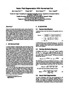
Fig. 1.
C. Guidewire Segmentation Many researchers have worked on mathematical algorithms to locate and track endovascular tools like guidewires on fluoroscopic images. The motivation of such research is either to enhance the planar display or to produce a 3D representation of the tools inside the vascular structure. Palti-Wasserman et al. [11] began in 1997 with the tracking of guide wires during coronary arteries navigation for angioplasty. Images are filtered to enhance linear structures to be tracked by a seconddegree polynomial using the Hough transform. A digital tool is then projected back on live fluoroscopic feed. Baert, van Walsum et al. [12], [13] transformed the endovascular tools tracking from biplan setup to 3D digital scene using a stereoprojection matrix. A single guide wire is segmented from a first pass of template matching followed by a refined positional adjustment by a snake-energy-based fitting optimization algorithm. They performed successfully a small offline clinical study but the required calculation times prevented real time implementation. The CardiOp-B team have started to work on the tracking of single guide wires during cardiac intervention [14]. The guide wire endpoints are detected and paired to represent distinctive tools. This simple implementation only addresses single small guide wires. More recent work by Barbu et al. [15] present a guide wire tracking method based on line segments detection filter from which segments are connected to reconstruct linear objects. It is dedicated to track single guide wires from live fluoroscopic images. The connection method is tuned by a hierarchical algorithm called the Probabilistic Boosting Tree. Although the learning phase can be long, the resulting tracking algorithm can be implemented in real-time and has shown promising results in offline studies. III. P ROPOSED M ETHOD We are proposing a new method that combines the enhancement and the segmentation operations in a continuous sampling algorithm. The enhancement is performed by a steerable filter aligned on the previous edge sample orientation. Thus the filtering and the segmentation are performed simultaneously on restricted regions surrounding the object of interest in a sweeping progression scan. Such a process
Propagating vector in 2D.
reduces substantially the computational requirements while still benefiting from precise enhancement filtering. A. 2D Automatically Steered Filter On an image, an automatically steered filter can be used to segment a continuous contour in an incremental progression. On image I(x, y) of size m by n, let us define a fixed length vector V of position (xv (u), yv (u)), constant speed υ, and orientation θ(u). This vector is moved in the image by tracking a contour. Although unknown, the contour can be represented by a function f . The numerical differentiation at f (u) is f (u + 1) − f (u − 1) . (1) 2 The motion of the vector is a function of u, which is the differentiation step, of value ν in this example. The local slope value f ′ (u) can serve as a steering filter alignment inside a kernel window centered on (xv (u), yv (u)). This kernel is of circular shape to equalize the length of cropped lines of all orientations passing through the center. Fig.1 shows the circular kernel centered on the vector tracking a line on a gray value image at a certain instant u. The line segment slope inside the filtered kernel window is computed by the Radon transform [16], the most suited algorithm to rapidly detect a bright line inside a circle. The highest Radon calculated number gives the most probable line segment orientation. In the possible case of line junction or branching, the Radon transform will highlight more than one probable path that can be processed accordingly. The incremental calculation is performed by the knowledge of the previous position along the line and the local slope. Thus, the next position is calculated by isolating f (u + 1) from equation 1. f ′ (u) =
f (u + 1) = 2f ′ (u) + f (u − 1) .
(2)
The slope is mapped to a specific direction, θ(u). The tracking functions in Cartesian coordinates are xv (u + 1) = xv (u − 1) + 2ν cos(θ(u)) ,
447
(3)
World Academy of Science, Engineering and Technology 54 2009
has a constant length υ, and its endpoints are o Pv1 and o Pv2 . The orientation possibilities of a vector in space represent a sphere. Because the vector is always in a forward motion, a half-sphere constitutes the only forward possibilities. The half-sphere projection on each plane defines the kernel for line enhancement on each image (as shown in Fig. 2). By projecting the line-enhanced gray values back inside the halfsphere and summing in both planes, the highest value inside the sphere points to the most probable 3D tracking point. The kernel projection on each plane can be calculated from the projection matrix. First, each 3D point can be decomposed in Cartesian coordinates, for example o
Pa = [ o ax o ay o az ]′ ,
(5)
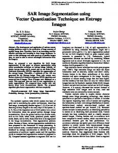
Also, each point can be transferred from an origin to another. For example Fig. 2.
Propagating vector in 3D from biplane projections. a
yv (u + 1) = yv (u − 1) − 2ν sin(θ(u)) .
Pv1 = ao R o Pv1 + a Po = oa R−1 ( o Pv1 − o Pa ) ,
(6)
(4)
The vector moves from an initial manually selected (or from an endpoint detection algorithm) position until a second suitable endpoint is detected (for an open contour). For an automatic endpoint detection, the local edge intensity mean along the sweep can serve as a threshold value to stop the scan at a sudden edge drop. Other cases like branching can be processed from the Radon intensity results presenting more than one straight-line outcomes. Then, the full segmentation is completed when all vectors have stopped propagating. B. Biplane Automatically Steered Filter A tracking vector is also suited (and more efficient) for edge segmentation on a biplane imaging modality. Instead of relying on projection, the vector propagates in the real object space (in 3D). Thus the object contour is realistic and not subjected to projection overlays. In such a case, the biplane images serve as external forces applied on the 3D vector. The position transformation matrix and image source of each projection are used for the segmented contour reconstruction in the 3D scaled world. Fig. 2 represents this concept of 3D reconstruction of a linear object projected on two planar sensors. The projection schemes have cone shapes, from a single image source to a planar sensor, mimicking the x-ray imaging technology of an angiogram. The projection of a fixed length 3D vector on each sensor outlines a region of interest in which line segments are enhanced. Thus an external force is applied on the 3D vector direction, which is proportional to the relative parallelism offset between the vector and the sensor panel. Considering a stereo-projection modality, the projections of plane a and plane b are referenced to the same origin o. Each plane is associated to a fixed position in space (o Pa , o Pb ), a focal origin (o Psa , o Psb ), and an orientation matrix o (a R, ob R). The 3D contour of interest is represented by a function f and a tracking vector V is used to segment it. V
The projection of o Pv1 on plane a (noted a v1′x ) can be solved using the location of the ray origin, a Psa . This focal origin is, by definition, on axis za . a
a
v1′x =
v1x a saz , a v1′y = a sa − a v1 z z
a
v1y a saz . a sa − a v1 z z
(7)
The kernel shape determined from the vector’s half-sphere projection is a partial ellipse because the projection scheme is conic. The next position increment in space f (u + 1) is not calculated by the Radon transform (as in the 2D algorithm of Section III-A), but directly from the projection inside the sphere. In an orthogonal biplane setup, the projection on the sphere would have a “+” shape whose intersection center would mark the 3D path to follow. The tracking terminates when the full segmentation is complete, i.e. when the edge intensity fades on both planes. IV. E XPERIMENT The proposed algorithms were tested on fluoroscopic medical images since they are very difficult to process. Fluoroscopy is a low-dose x-ray system that has low resolution and high Poisson noise. Because the radiation is low, the noise level is very close to the signal amplitude. The purpose of lowdose is to reduce exposure to the patient and nearby medical practitioner to a minimum because fluoroscopy is used continuously (video feedback). The fluoroscopy samples of Fig. 3 are simultaneous biplane projections taken during a cerebral endovascular intervention. The resolution is 512 x 512 and the gray intensity is on an 8-bit scale, although the overall image levels are inside an approximate 30 grey level margin. The experiment objective is to segment the guide wire present in both images under real-time conditions since the images are from a 15 frames per second sequence. The 2D segmentation algorithm using a vector presented in Section III-A was tested on both images. Fig. 4 shows the
448
World Academy of Science, Engineering and Technology 54 2009
Fig. 3.
Biplane fluoroscopic images of cerebral endovascular intervention.
results. The segmentation failed on the left when the vector reached an intersection. The intersection’s small angle caused a long overlap that prevented the vector from choosing the proper path. Also, the corner angle sharpness restrained the vector from continuing its propagation. The biplane segmentation from the algorithm presented in Section III-B succeeded in segmenting accurately the guide wire in 3D. The intersection problem in one projection plane was overcome by the 3D trajectory of the vector, relying on the biplane correspondence. Fig. 5 shows the 3D scene with the 3D guide wire and its projection on both planes.
Fig. 4.
2D segmentation using automatically driven vector.
Fig. 5.
3D segmentation using automatically driven vector.
This method reduces calculations by partially filtering the images and by relying on simple kinematic functions. The steerable filters used also increase edge detection sensibility. Its effectiveness was tested successfully on particularly difficult to process medical fluoroscopic images. While the 2D implementation was able to segment relatively smooth curves but failed to sort intersection branches, the biplane implementation was able to cope with the overlay problem by relying simultaneously on the stereo-projections. The next step of this research axis is to elaborate performance measures (precision and computational time) on a large number of images, thus allowing the algorithm to be implemented in software dedicated to endovascular intervention. ACKNOWLEDGMENT This work was supported by the Natural Sciences and Engineering Research Council (NSERC) of Canada, CRD Project with Siemens Canada Ltd.
V. C ONCLUSION This paper presented a new method for guidewire segmentation, during endovascular intervention, based on a tracking window that filters locally while advancing on an edge.
449
World Academy of Science, Engineering and Technology 54 2009
R EFERENCES [1] L. Guimar¨aes, A. Soares, V. Cordeiro, and A. Susin, “Gradient pile up algorithm for edge enhancement and detection,” Image Analysis and Recognition, vol. 3211, pp. 187–194, 2004. [2] E. Franken, P. Rongen, M. van Almsick, and B. M. ter Haar Romeny, “Detection of electrophysiology catheters in noisy fluoroscopy images,” in MICCAI, 2006, pp. 25–32. [3] A. F. Frangi, W. J. Niessen, K. L. Vincken, and M. A. Viergever, “Multiscale vessel enhancement filtering,” in Medical Image Computing and Computer-Assisted Intervention, ser. Lecture Notes in Computer Science, vol. 1496, 1998, pp. 130–137. [4] J. George and S. Indu, “Fast adaptive anisotropic filtering for medical image enhancement,” Dec. 2008, pp. 227–232. [5] K. Lai and R. Chin, “Deformable contours: modeling and extraction,” Pattern Analysis and Machine Intelligence, IEEE Transactions on, vol. 17, no. 11, pp. 1084–1090, Nov 1995. [6] M. Kass, A. Witkin, and D. Terzopoulos, “Snakes: Active contour models,” International Journal of Computer Vision, vol. V1, no. 4, pp. 321–331, January 1988. [Online]. Available: http://dx.doi.org/10.1007/BF00133570 [7] C. Xu and J. Prince, “Snakes, shapes, and gradient vector flow,” Image Processing, IEEE Transactions on, vol. 7, no. 3, pp. 359–369, Mar 1998. [8] I. Ben Ayed and A. Mitiche, “A region merging prior for variational level set image segmentation,” IEEE Transactions on Image Processing, vol. 17, no. 12, pp. 2301–2311, Dec 2008. [9] P.-L. Bazin and D. L. Pham, “Topology correction of segmented medical images using a fast marching algorithm,” Comput. Methods Prog. Biomed., vol. 88, no. 2, pp. 182–190, 2007. [10] G. Langs, P. Radeva, and F. Carreras, “Explorative building of 3d vessel tree models,” in 28th annual workshop of the Austrian Association for Pattern Recognition, 1999. [11] D. Palti-Wasserman, A. M. Bruckstein, and R. P. Beyar, “Identifying and tracking a guide wire in the coronary arteries during angioplasty from x-ray images,” IEEE Transactions on Biomedical Engineering, vol. 44, no. 2, pp. 152–164, Feb 1997. [12] S. A. M. Baert, E. B. van de Kraats, T. van Walsum, M. A. Viergever, and W. J. Niessen, “Three-dimensional guide-wire reconstruction from biplane image sequences for integrated display in 3-d vasculature,” IEEE Transaction on Medical Imaging, vol. 22, no. 10, pp. 1252–1258, Oct 2003. [13] T. van Walsum, S. A. M. Baert, and W. J. Niessen, “3d guide wire visualization in 3dra using monoplane fluoroscopic imaging,” in SPIE Medical Imaging, vol. 5029, 2003, pp. 166–175. [14] M. Zarkh and M. Klaiman, “Guide wire navigation and therapeutic device localization for catheterization procedure,” in Computer Assisted Radiology and Surgery, vol. 1281, May 2005, pp. 311–316. [15] A. Barbu, V. Athitsos, B. Georgescu, S. Boehm, P. Durlak, and D. Comaniciu, “Hierarchical learning of curves application to guidewire localization in fluoroscopy,” IEEE Computer Vision and Pattern Recognition, pp. 1–8, June 2007. [16] S. R. Deans, The Radon Transform and Some of Its Applications. Krieger Publishing Company, June 1992.
450