Automating Applications Management in the Enterprise using DMTF Information Models Umesh Bellur
Indian Institute of Tech. Bombay Powai, Mumbai 400076 India +91 22 25767865
[email protected]
ABSTRACT
Most enterprises today are heavily if not completely dependent on systems for the running of the business. Applications that automate business operations are mostly based on distributed, component based architectures where advances in server side component models have considerably simplified development. The simplicity of constructing these applications has resulted in an increased complexity on the operational side of managing the component tapestry. The increase in operational complexity has reached a point where it is no longer feasible for humans to manage the applications and infrastructure required to run an enterprise. The initial steps to provide self managing application environments are now being taken – a paradigm known as “autonomic computing” is in it’s infancy of evolution. DMTF specifications that are currently being developed for management of distributed applications form the basis for some of this work. There have been numerous proposed models of how one achieves self management. In this paper, we formulate the research problems and basis for “lights out” management of enterprise application environments. We also illustrate our approach with a way of managing simple web applications based on Java Servlets.
Categories and Subject Descriptors
D.3.3 [Run time Environments]: Distributed Autonomic computing, and Analytical methods.
systems,
General Terms
Management, Measurement, Performance, Physical Design, Reliability.
1. INTRODUCTION
As more distributed applications become mainstream enterprise solutions, there have been considerable advances in making the development of these applications simpler. The development of
Copyright:
server side component models followed by standardization of server side “software containers” to host these components have helped considerably shorten the development lifecycles of large applications. Indeed it is not uncommon to see release cycles of 6 months or less in the enterprise for major features and 3 months or less for minor feature adds. The impact of these rapid application development paradigms has shifted the complexity from what used to be development to deployment and beyond – tasks that are commonly handled by the IT Operations staff in the enterprise. Once the application has been developed, the first task would be to map it to physical infrastructure given the expected workloads and the availability of shared physical resources (CPU, disk, network bandwidth etc.). Once resource mapping is done, the various resources need to be configured with the appropriate parameters to handle the application. This in itself is a task of great complexity not only because of the dependencies between the various components making up an application but also because one needs to map any QoS requirements of the application (such as response times and uptime) to the selection of the different physical components that the application will run on. For example, network QoS may have to be negotiated appropriately since network communication quality can have a significant impact on application performance of distributed applications. The complexity also arises from the numbers of parameters that have to be tuned on resources such as application servers and relational databases. The modern J2EE1 application server has over 300 parameters that have to be tuned in order to extract the best value. Subsequently, monitoring the application with a view to resolving faults that may occur as well as keeping the performance tuned in spite of varying workloads is also a daunting task – one that is amplified by the presence of several such applications running on the enterprise’s wide and/or local area network. Empirical evidence suggests that it is impossible to manually handle and automating these tasks is a necessity. Of late, there has been an increased focus on “autonomic computing” techniques – techniques that determine how application environments can configure and heal themselves in the event of problems. For example, an application server (or 1
Page 1 of 6
J2EE is a trademark of SUN and denotes the server side Java component architecture commonly used to build enterprise applications today.
middleware server) can have over a hundred different parameters that have to be tuned.
containers), its configuration and its dependence on the underlying network.
In this paper, we first present an application management architecture that spans resource discovery to fault detection, isolation and correction. We are in the process of realization of this architecture and this paper represents work in progress towards the goal of what is termed zero-touch or lights out management2. This is the LAMDA (Lights-out, Automated Management of Distributed Applications) project being done at IIT in conjunction with the industry.
b.
The static view application components and their configurations.
c.
The dynamic or run time view of application components that execute on the infrastructure. This specifies the physical footprint that the component exhibits at run time. For example, an EJB can be deployed on several J2EE containers either as a cluster or singly.
d.
Dependencies that exist between application components, between application components and infrastructure (software, hardware and network).
2. The LAMDA Vision
There are several facets to autonomic computing all of which form part of the LAMDA vision. a.
Systems Architecture and deployment – Self Configuration. There are two aspects to this – static and dynamic. Static design lays out certain constraints on location of the application components and maps it initially to a physical topology. The dynamic version ensures that these constraints continue to be met and may move application components, add or remove computing resources and reconfigure the infrastructure.
b.
Root Cause Isolation and correction - Self Healing. Self healing can be for the purposes of correcting a structural constraint or property that has been broken such as those related to performance, availability or capacity.
c.
Self Protection – Related to the second facet, this is for the purposes of healing a security breach that has occurred. The techniques and the basis for self protection are often very different from those used for self healing and so will be considered separately.
As a part of this effort (especially part a), we have also developed meta models for describing application QoS parameters and resource needs which we use in trying to come up with the physical design.
Topology is a realization of the meta-model that characterizes applications and their execution environments and provides a canonical language for common understanding of what an application is and what it depends on. Every tool in the LAMDA arsenal works off of topology. Since the topology of a distributed shared execution environment is constantly changing (applications are being added, removed or updated, machines are upgraded or added, the network is being tuned etc.), we need a process that will keep up-to-date the topology of the existing environment including any applications that are currently executing on it.
Applications eBusiness Portal
B U S I N E S S
Order Mgmt.
Inventory
Billing
Ordering Service
Online Bill Payment Service
S V C S
2.1 The Basis of LAMDA
Web Component
Business Logic Component
DB Component
2.1.1 Structural Basis - Topology
The starting point for self-healing or self configuration is to know one self and so determining the topology of the application in relation to its execution environment is critical. An application cannot be deployed without knowledge of the various components that make it up. Both the static parts of the component (viz, it’s packaging) as well as it’s physical footprint need to be well understood for problem isolation and correction. Topology therefore is a description of: a.
2
The infrastructure (both physical such as compute servers as well as logical such as server component
Lights Out management is a term commonly used in the IT industry to indicate that no human is needed to manage these applications.
Page 2 of 6
In LAMDA, we differentiate between applications and services as follows. Applications are considered as units of deployment which bind together a set of components to be deployed as a group. For example the Order Management application can have 2 EJBs3 representing order processing business logic, a DB component representing the order schema and a set of JSPs4 that represents the interface into ordering, order status determination etc. 3
EJB stands for Enterprise Java Beans which are server side components in the J2EE architecture.
4
JSP stands for Java server pages which are server side pages than are used to generate dynamic web pages in web applications.
Business services are transactions that have a clear customer access point such as a web site link or a GUI button that can start the transaction. Business services thread through various applications touching individual components along the way. Quality of Service (QoS) requirements should exist on business services such as the bill payment service will have availability of 99.9% with 85% of the transactions exhibiting response times of less than 1 second! Applications themselves may have individual QoS but that is relatively less important. The two of these concepts are orthogonal. Developers are concerned with applications that encapsulate some functionality while IT administrators are concerned with managing services as seen by the customer.
2.1.2 Topology and DMTF
The topology of the environment which forms the basis for most of the work once determined will need to be stored in a topology model. This is where DMTF comes in. We have adopted the DMTF descriptions and information models of distributed applications as well the management interfaces given by JSR77 to store our topology. The application server model which is currently under development as well as the models of systems is being used to store the data extracted from our discovery process. We have also extended these where required and are in the process of putting together XML interfaces to extract the data.
2.1.3 Analytical Basis
In order to have a predictive model of both capacity management as well as potential failures, we need an analytical model of an application and its execution infrastructure that we can solve under the constraints specified by the needed application QoS. For the purposes of self configuration as it relates to performance tuning and capacity management we are using Hierarchical Queuing Petri Nets (HQPN) to model our environment. HPQNs are a variation of Colored General Stochastic Petri Nets and stochastic queuing models where we can build hierarchies of such Petri nets recursively. Every place can be attached to a Queue to represent scheduling policies and waits. The hierarchy is built up by folding the sub Petri net to represent a single place which has a timed wait. HQPNs have been employed in similar situations to analyze application performance and the component model of deployment is particularly well suited to be modeled using HPQNs. For further information on HPQNs, we refer the reader to [15]. They translate to their underlying Markov chains which can be solved using well understood methods such as LQ decomposition. The architectural basis for self healing however is still in the formative stage but we are leaning towards using multi-agent architectures (MAS) coupled with distributed correlation algorithms that correlate across the network, compute and software infrastructure layers. MAS gives us the ability to decentralize decision making as it related to root cause isolation and also adds the notion of machine learning which is needed in trying to isolate root causes from a variety of patterns that occur in these complex environments.
Page 3 of 6
2.2 LAMDA Architecture
LAMDA is essentially a closed loop optimization process. The input to this process is a set of applications along with their QoS needs and expected workloads. Initial physical design is a byproduct of the analysis and optimization process of the architecture but we expect this is a continual process driven by changes in the underlying infrastructure as well as workloads. The underlying infrastructure which is pre-built based on our knowledge of the functioning of the containers, is augmented with the knowledge about the topology of the application. So, for example, if the application calls for a particular servlet to talk with a specific DB schema, then we can build the underling analytical model for performance analysis. We then solve the analytical model and obtain the expected QoS under a particular physical design. This is iteratively refined by moving around components to optimize for the QoS parameters till we meet or beat the expected QoS of the application. Of course, this optimization has to be performed with all the applications that share a common infrastructure, else it will not be of much use in a real environment. The same approach can be used to optimize the number of resources used as well and output the best expected QoS from the application.
Auto
Topology
Discovery Application QoS Requirements
Workload
Analysis of
Characterization
Performability
Runtime Physical Design
Designer
Monitoring, Fault Detection, Correction
Figure 1: The Process Architecture of LAMDA
3. Application to Web Application System Design for Java Servlets
In this section, we will look into the application of the principles described in earlier sections to the system design of servlets containers. For simplicity, we are looking only at J2EE applications currently although the techniques are likely to be useful across a variety of similar component models such as .NET and CORBA. The first of these models is that of a web application that consists of a simple Web Server/Servlet container that hosts dynamic content generation pieces of Java code known as Servlets. As a simplification in our first model, Servlets execute independently and don’t need to access backend resources for either business logic or data. Given a servlet, we are able to model it’s execution analytically using Queuing Petri-net models which can be used to predict performance based on reward rates of the underlying Markov chains. We are using this information to then configure the Web Server and container according to the QoS needs of the application.
3.1 Tomcat and It’s QPN Model
In order to study the performance and subsequently apply it to physical design, we use the Apache Tomcat Servlet container as our reference architecture.
3.1.1 The Tomcat Concrete Architecture Conceptually, TOMCAT is split into two parts - a connector which is tasked with handling the communication protocol and it’s details and a backend server which is the actual Servlet container.
b.
The adapter assigns a thread from the thread pool. c. The request is then associated with HttpRequest and Response objects also obtained from a pool. The request HTML is parsed and the individual fields in the Request and Response are filled in. Parsing may be just-in-time as well. d. The request is passed through a user defined pipeline of filters where each step of the pipeline does some (user defined) processing on the Request and Response objects. e. It then gets mapped to a virtual host which then processes the request through its own pipeline of filters. f. The request is then associated with the context of the web application with which it is bound. g. The appropriate Java classes are loaded using the right class loader. This step may be skipped if the classes have already been loaded and have not been invalidated by a new deployment. h. Finally, the request is associated with an instance of the servelet and the service() method of the servlet is called, which in turn generally maps the type of HTTP request to appropriate method of the servlet. i. After the servlet finishes processing, the response object flows through the same path, freeing up resources which it had earlier acquired and returning objects to respective pools. j. Finally, the Response is converted back to HTTP response over the socket stream. The above description shows that simply modeling the execution of a servlet as a single queue is not appropriate and we need to ensure that the different aspects of request processing need to be taken into account in the analytical model for it to be accurate.
3.1.2 The Analytical QPN Model of Tomcat
Figure 2: The Architecture of Tomcat The server itself is built in a pipelined fashion making it possible to have multiple requests flowing through the system even as multiple threads are used to concurrently process requests. The concrete architecture of Tomcat is shown in Figure 1. When a HTTP request arrives at the Tomcat, these are the set of steps that occur in sequence: a.
Page 4 of 6
It is handled by the Coyote protocol adapter.
Figure 3: Simplied QPN Model of TOMCAT
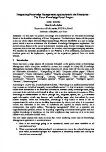
Thread pool size = 1
Response time (ms)
3000 2500 2000 Model Results
1500
Experimental Results
1000 500 0 1
The figures shows above depict the analytical model of TOMCAT when executing servlets. We have employed a single colored Stochastic Petri Net notation for now although different servlets can be treated by the use of multiple colored tokens. Essentially anything that is a source of contention can be represented by a queued place while any point in the servlets container that is an activity can be represented by a simple place and a transition. The model itself has been considerably simplified compared to the structural model of TOMCAT because of two main reasons: a.
b.
The simplified model is roughly equivalent to the structural model with the proviso that a constant amount of time is allocated to the initial activities of parsing the HTTP request, assigning a request and result object to the request and then sending it on it’s way for further processing. This is constant for any servlets that is executed within the container. The original model which we had come up with resulted in state space explosion which most tools that solve these models cannot handle.
The simplified model works quite well for our needs as we shall see in the section on performance analysis.
4. Performance Analysis We have solved these models with pre-specified ratio of processing to I/O time of the servlets and samples of the results are shown below. The results allow us to compare the performance of the servlets in terms of end to end response time as generated by the model and as measured on TOMCAT directly.
Page 5 of 6
2
3
4
5
No. of users
In this particular example, the reason why the response time is increasing linearly with the number of concurrent clients is because the thread pool size is set to 1 implying that multiple requests have to queue and wait to be allocated a thread before they can proceed with processing. Increasing the thread pool size will see the response time being flat up to the number of threads and then increasing linearly as is expected. The key point to take away from this is that we now have a fairly accurate predictor of performance of a web based application without having to test it under varying load conditions. Confidence in the model can only improve with a more detailed look at the activities within TOMCAT and given that our initial predictor is fairly accurate, we are moving on to looking to modeling DB interaction and middle tier components such as EJBs which are significantly more complex in nature.
5. Current Status
This project was born out of the experience of several system administrators who had the first hand experience of setting and managing service QoS on multiple applications in a shared data center environment. Since then we have added an analytical flavor to the application management process architecture. We have currently implemented a functional Discovery subsystem which works off the meta-model described in earlier sections. This tool does auto discovery of a networked environment and can discover and map the topology of: a.
Compute layers consisting of heterogeneous operating systems (SUN Solaris, Linux etc.) and classes of machines.
b.
Software infrastructure such as Apache Web servers (Version 1.3+), J2EE Application Servers (JBOSS Version 3.0+) and Oracle Databases (Version 8 and 9).
c.
Application components such as Servlets/JSPs, Enterprise Java Beans and DB Schemas along with their interdependencies.
[6] Ganek, A., “A letter from Vice President, Autononomic
The starting point for this tool is a range of IP Addresses which serves as the bounds of discovery. We have also performance benchmarked this tool up to a 300 server data center environment and performance is more than adequate at about 15 seconds for a 100 servers with linear increase. We have also proved that Discovery consumes less than 3% of the system resources to run.
[7] Garlan, D. and Schmerl, B., “Model-based Adaptation for
We have also started our analytical modeling efforts and now have models that can run off the discovered topology for performance prediction. We have illustrated the TOMCAT model here and are in the process of putting together such models for enterprise applications that are N tier.
Computing, Alan Ganek” 3.ibm.com/autonomic/letter.shtml, 2002.
http://www-
Self-Healing Systems”, ACM WOSS, Charleston, SC, USA., 27-32, Nov., 2002.
[8] George S., et al., “A Biologically Inspired Programming Model for Self-Healing Systems”, ACM WOSS, Charleston, SC, USA., 102-104, Nov., 2002.
[9] IBM paper-1: “IBM autonomic computing challenges note: academic focus article: challenges”, http://www.research.ibm.com/autonomic/academic/challenge s.html, 2002
[10] Mikic-Rakic, M., et al., “Architectural Style Requirements
6. SUMMARY
To tackle the growing complexity of managing distributed/networked applications, we have proposed management architecture for autonomic computing of such environments. The LAMDA architecture revolves around the environment’s topology for which we have developed a metamodel.
for Self-Healing Systems, ACM WOSS, Charleston, SC, USA., 49-54, Nov., 2002.
[11] Patterson, D., et al., “Recovery Oriented Computing (ROC):
Motivation, Definition, Techniques, and Case Studies”, In Proceedings of the UC Berkeley Computer Science Technical Report UCB/CSD-02-1175, Berkeley, CA, March 2002.
[12] Tivoli software, “Autonomic Computing: The Value of Self Managing Systems”, http://www.tivoli.com/news/features/oct2002/autonomic.htm l, 2002.
Although the work is ongoing, this paper states our position on the architectural approaches that are required to deal with the issues holistically. We feel that there will be significant benefit to interact with the other researchers in the area who may be taking other approaches and that the exchange of ideas will benefit all concerned.
[13] Vaidyanathan, K., Selvamuthu, D., and Trivedi, K. S.,
7. REFERENCES
[14] Probability and Statistics with Reliability, Queueing and
[1] Bigus, J. P., et al. “A Toolkit for Building Multiagent AutonomicSystems”, http://www.research.ibm.com/journal/sj/413/bigus.html, 2002.
[2] Blair, G., et al., “Reflection, Self-Awareness and SelfHealing in OpenORB”, ACM WOSS”, 9-14, Nov., 2002.
[3] Dabrowshi, C. and Mills K., “Understanding Self-healing in
Service-Discovery Systems”, ACM WOSS, Charleston, SC, USA., 15-20, Nov., 2002.
[4] Dashofy E. M.m et al., “Towards Architecture-based Self-
Healing Systems”, ACM WOSS, Charleston, SC, USA., 2126, Nov., 2002.
[5] Fox A. and Patterson, D., “When Does Fast Recovery Trump
High Reliability?”, Proceedings of the EASY 2002, San Jose, CA, October 2002.
Page 6 of 6
Analysis of Inspection-Based Preventive Maintenance in Operational Software Systems, Intl. Symposium on Reliable Distributed Systems, SRDS 2002, Osaka, Japan, October 2002 Computer Science Applications, Kishore S. Trivedi, ISBN 0471-33341-7, John Wiley and Sons.
[15] F. Bause, P. Buchholz and P. Kemper – QPN Tool for the Specification and Analysis of Hierarchically Combined Queueing Petri Nets. Quantitative Evaluation of Computing and Communication Systems, Lecture Notes in Computer Science No. 977, Springer-Verlag, 1995 [16] DMTF CIM Specifications. http://www.dmtf.org