Generating Enterprise Applications from Models. Vinay Kulkarni, R Venkatesh, Sreedhar Reddy. Tata Research Development and Design Centre,. 54, Industrial ...
Generating Enterprise Applications from Models Vinay Kulkarni, R Venkatesh, Sreedhar Reddy Tata Research Development and Design Centre, 54, Industrial estate, Hadapsar, Pune, 411 013, INDIA { vinayk, rvenky, sreedharr } @pune.tcs.co.in
Abstract. For developing large and complex applications, industrial practice uses a combination of non-formal notations and methods. Different notations are used to specify the properties of different aspects of an application and these specifications are transformed into their corresponding implementations through the steps of a development process. The development process relies heavily on manual verification to ensure the different pieces integrate into a consistent whole. This is an expensive and error prone process. We present a set of notations for specifying the different layers of a software architecture and a method for transforming a specification into an implementation. Models defined using these different notations are instances of a single meta model. This provides a means to unify the specifications of different layers and leads to a simple and elegant implementation method. The method has been used extensively to construct medium and large-scale enterprise applications.
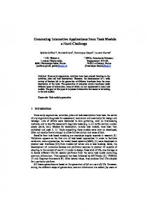
1 Introduction Faced with the problem of developing large and complex applications, industrial practice uses a combination of non-formal notations and methods. Different notations are used to specify the properties of different aspects of an application and these specifications are transformed into their corresponding implementations through the steps of a development process. The development process relies heavily on manual verification to ensure the different pieces integrate into a consistent whole. This is an expensive and error prone process. In this paper we address the problem of managing scale and integration of application development. Scale and complexity are addressed by breaking down the problem along different axes – functional, architecture and development process (Fig. 1). Functional break up results in various components. For a layered architecture the application is split up so that each piece implements the solution corresponding to a layer in the architecture. Different phases of the development process determine the properties of the application that are to be specified (implemented) during a particular phase. For example, a banking system may be broken down into different functional components like Foreign Exchange, Retail banking etc. A functional component like Retail banking will have a User Interface layer describing the way a user interacts with the system, an Application layer implementing the business functionality and a Database layer making information persistent. A development process consisting of phases
such as Analysis, Design and Implementation will implement different properties of a layer. The Analysis phase for the user interface layer of Retail Banking will define the screen layout. The Design phase will identify the controls to be used and define the user interface standards. The Implementation phase will code the user interface in the chosen platform.
UI prototype
UML diagrams
Design
GUI standards
Design Strategies
ER diagrams + Table design
Coding
JSP implementation
C++/Java code
RDBMS Implementation
User Interface(UI)
Application
Database
Analysis
Fig. 1. Break up of application based on development phases and architecture layers
It is a common practice to split up an application into different functional components. With regards to architectural layers and development phases there have been various unrelated attempts. Entity Relationship (ER) modeling [3] is popular for specifying information content of an application. Unified Modeling Language (UML) [2] provides different notations without clearly stating the relationship between specifications defined using these notations. A given UML notation can be used to express different properties. For example, an activity diagram can be used to specify control flow within a function as well as a business process. Therefore, a UML specification cannot be unambiguously transformed into an implementation. There is a need to define a set of notations having well defined semantics that will enable unambiguous transformation of a specification to its corresponding implementation. The set of notations should allow specification of all aspects of interest of an application – it should be complete with respect to the aspects of interest. In this paper we present a set of notations and a method for constructing an enterprise class application using these notations for specifying the different architecture layers. Models defined using these different notations are instances of a single meta model. The meta model specifies the structure and constraints between the related model elements [4]. This provides a means of unifying the specifications of all the properties of the application that is constructed using these models leading to a simple and elegant implementation method. The method has been used extensively to construct medium and large-scale enterprise applications. We first describe a possible set of architecture layers in which the development of an enterprise application can be decomposed. We propose models to specify these
layers and the relationships between them. We show how each layer can be independently transformed into its implementation without compromising the integrity of the application. For clarity, we have used meta-modeling approach to illustrate the idea in a diagram. We conclude with advantages of the approach and some problems that remain to be solved.
2 The use of modeling for application development The development of an application starts with an abstract specification A which is to be transformed into a concrete implementation C on a target architecture [5]. The target architecture is usually layered with each layer representing one view of the system. The modeling approach constructs A using different abstract views A1…An , each defining a set of properties corresponding to the layer it models. A view, Ai, is an instance of a more general structure that can be represented as a model Mi, e.g. user interaction model for sequences of interactions between the user and the system or an entity-relationship model for representing data. Note that A is usually not available separately: A is used here to represent the composition of the views A1…An . A view is the means by which one set of abstract properties are specified and implemented through a corresponding set of transformation mechanisms, i.e. by transforming each Ai into a corresponding implementation Ci. The application level composition of C1…Cn gives C, which is the intended implementation of A. Each Ai can be transformed into Ci manually, but this is then required to be done for each such application. Instead, we make use of the model Mi, of which Ai is an instance, and implement general transformations at the model level. These transformations can be applied to all instances of Mi. Defining transformations at the level of Mi, rather than Ai, makes it possible to scale-up the method to handle large programs. For example, a transformation can be specified from Class diagram to Java classes. This transformation can be applied to generate Java classes for any application.
3 Architecture of a client-server application An enterprise application is implemented across three architecture layers – user interface, application functionality and database. Each layer is implemented on a different platform supporting different primitives. For example, User interface platforms like Visual Basic provide windows and controls as implementation primitives. Application logic is implemented in a programming language like Java with classes and methods as the primitives while the database layer is implemented using tables and columns in a relational database system. These three layers are implemented independently and combined later to get an implementation C. A good specification should be capable of refinement and reflect the structure of the implementation. It should use the same vocabulary across different development phases. For example, if the implementation is using Classes the Analysis should be expressed as class diagrams. This enables easy transition from analysis to code. Since
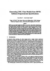
the implementation primitives are different for each layer we also need a different specification notation corresponding to each layer. The specification should also clearly bring out the relationships between the different layers. Having separated the notations we can now define corresponding models and transformation on each model. These transformations can be carried out independently for each layer. The relationships between models specify part of the invariance to be satisfied by individual transformations. The transformation of the relationships between the layers will guarantee that the different Cis will integrate to give a consistent implementation C. The following sections describe the different models – Application, User Interface and Database, of a client server application in greater detail. For brevity, we have left out many details from each of the models. 3.1 Application The business proess and information content of the application are modeled in the analysis phase. A business process models application as a set of tasks and defines the order in which these tasks are executed. Each task is implemented by a method. The application layer implements the business process, the business logic and business rules. The business logic is best modeled using classes, attributes, methods and associations between classes. This layer can be specified as an instance of the model in Fig. 2. Business logic is typically coded in a programming language. Example: A banking system allows a user to open and operate an account with a bank. Two classes corresponding to this system are User and Account. An association between User and Account specifies the account belonging to a user. Account number is an attribute of Account and name is an attribute of User. The account opening process involves filling up an account opening form, verification of the form and approval of the form. A user can operate the account only after it is approved.
Class
Process
* *
1..* has
1..* has
precedes
source 1..* *
* Task
* Method
*
* realizes
Association 1..* has
1..* * destination
* Attribute * ofType 1..* DataType
Fig. 2. Model for Application layer
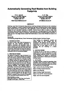
3.2 User interface A user interacts with an application through its user interface. The user feeds in information using forms and browses over available information using queries and reports. Forms, queries and reports are implemented in a target platform using standard graphical user interface (GUI) primitives – windows, controls and buttons. A window is a unit of interaction between the user and the system and is composed of controls and buttons. A control accepts or presents data in a specific format. The user can perform a specific task by clicking on a button. Example: The user of a banking system needs a query window to inquire about past transactions and the current balance. She also needs a form window to withdraw money from her account. These windows will use appropriate controls to represent account number and date of transaction. The user interface is best specified in terms of the windows in the application, data to be shown in each window, controls to be used to represent this data, possible navigation between windows and actions that can be performed. The core of a model for such a specification is as shown in Fig 3. In the figure a UIClass represents a logical grouping of the data to be shown in a window. Each UIClass represents a view of the application data. The association mapsto between UIAttribute and Attribute defines the view. This enables a transformation to represent value of the Attribute on the Window correctly. This also ensures the user can enter only values that are valid for the attribute of a class. The association calls between Button and Operation enables transformation to ensure type-correct invocation of operation. This also ensures the right set of objects get created and passed as parameters to the method invocation. The mapsto association enables a transformation to copy the right values from window to the parameter objects. Additionally for a user interface to be good a particular data type should be represented by the same control in all the windows. In the banking system the same format should be used for all dates in all the windows. Similarly the same format
Window * has
* has
Class 1..* has
opens 1..* * Button
* UIClass 1..* has * UIAttribute
*
0..1
* Method calls
1..* has * Attribute 0..1
0..1
0..1 Fig. 3. Model for User interface layer
mapsto
should be used for account number in all the windows. An association between data type and control, as shown in Fig, 4, will allow specification of such GUI standards. Additionally for a user interface to be good a particular data type should be represented by the same control in all the windows. In the banking system the same format should be used for all dates in all the windows. Similarly the same format should be used for account number in all the windows. An association between data type and control, as shown in Fig, 4, will allow specification of such GUI standards. 3.3 Database layer The database layer provides persistence for application objects using an RDBMS, access to these tables based on primary key and arbitrary predicates, and an object oriented view of these accesses to application layer. In a relational database, the schema is made up of tables, consisting of rows and columns, where each column has a name and a simple data type. In an object model, the equivalent to a table is a class consisting of attributes and methods. A row in a table contains data for an instance of a class. Therefore, the mappings essential to object/relational integration are between a table and a class, between columns and attributes, and between a row and an object. This is shown in Fig 5. Example: The persistent information for the banking system will include details about accounts and users. Two tables User and Account implement this persistent information. These tables have columns corresponding to user name and account number. The association between a user and an account is implemented by having account number as a foreign key in the User table and a primary key in the Account table. Similar to the mapsto association of User Interface model, the mapsto association between Attribute and Column ensures type correctness. The implements association allows correct coding of class associations using appropriate Primary and Foreign keys. This association uniquely identifies the related classes and the tables. These
representedBy Control
*
*
instanceOf
DataType
instanceOf representedBy
CalendarControl
0..1
0..1
Fig. 4. A model for specifying GUI standards
Date
classes and tables must be related. Such constraints can be specified in the meta model.
4 Model validation Modeling of the application helps identify errors early in the development cycle. Associated with every model are a set of rules and constraints that define validity of its instance. These rules and constraints could include rules for type checking and for consistency between specifications of different layers as well as across different phases. Some of the validation rules for models presented so far are: - User interface should allow specification of all Tasks in the business process and be consistent with the precedes relationship between the Tasks - User interface should display data that is consistent with respect to the parameters being passed to the operations invoked from the Window - Database layer should ensure that implements association is implemented in a consistent manner. For example, the 1:M association between classes User and Account should be implemented by making the primary key of User table as foreign key of Account table.
5 Integration We have illustrated the advantages of having different notations to specify the
1..*
Class 1..* has
1..*
1..* destination
source
* * Association
* Attribute * ofType
Table
0..1
* Key
0..1
has
has
0..1 implements
1..* DataType
1..*
mapsto Fig. 5. Model for database layer
* Column *
1..* composed
0..1
different layers of an enterprise application. Corresponding to these specifications are the three models - Application layer model (AM), User interaction model (UIM) and Database layer model (DM). These models represent different views of the system. Specifying these models and the relationships between them as an instance of a single meta model (MM) ensures consistency of the application. The meta model specifies structure as well as constraints to be satisfied by the instances of related model elements. Having a single meta model ensures that instances A1, A2 and A3 of models UIM, AM and DM respectively can be transformed into corresponding implementations independently. These transformations can be performed either manually or using code generators. If individual transformation implements the corresponding specification and its relationships with other specifications correctly then the resulting implementations will glue together giving a consistent implementation C of the specification A. Fig. 6 depicts this framework. For the banking system, the specifications are as shown in Fig. 7. The association has between class User and class Account is implemented in the database layer by the column AccNo that is the Primary key in Account table and Foreign key in User table. Click of Deposit button invokes Deposit method of the corresponding Account. The above example illustrates the advantages of using different notations to specify the different layers of an application. Making these specifications into instances of a single meta model allows us to specify the relationships between the different specifications. The notations proposed have well defined semantics. These properties allow specifications to be independently transformed into implementations that are guaranteed to integrate into a consistent whole. The ability to develop an application by specifying each layer separately and transforming each specification into corresponding code addresses the problem of scale. In the following section we describe a tool that performs these transformations automatically.
MM
UIM
AM
DM
instanceOf
instanceOf A1
A2
instanceOf A3
C2 C1
C
C3
Fig. 6. Model based development and integration
Application
User Interface
User String Name;
Name A/c No
has
Amount Withdraw
Deposit
Account String AccNo; Double Balance; Withdraw, Deposit
Database User Name AccNo Account AccNo Balance
Fig. 7. Specifications for a banking system
6 Model driven software development environment The approach described above is well suited for model driven software development. This approach is realized in MasterCraft - a model driven software development environment [1] developed at Tata Research Development and Design Centre. This environment allows a user to model the three layers and the relationships between them independently (Fig. 8). This is achieved by extending the UML meta model with notations for User interface specification, Database specification and the relationships between all the three specifications. MasterCraft has code generators for each of the three layers – guimod, bxl and dmgen that translate the specifications and relationships between them into an implementation. These code generators guarantee consistency across the different layers. The above approach has been extended to enable specification of other aspects of interest such as security, business rules and business process. The development environment also provides an automated development process. Several large applications have been developed using MasterCraft on different platforms.
7 Conclusions We have presented the advantages of using different notations for different layers of application architecture. We have illustrated how having a single meta-model to describe the models corresponding to these notations and their relationships lends itself to an elegant implementation method. The implementation method allows independent transformations of specifications of the different layers and guarantees their integration into a consistent whole. The ability to develop an application by specifying and transforming each layer separately addresses the problem of scale. Though we have illustrated the approach using a three-layer architecture, it lends itself to any architectural decomposition that has well-defined layers with well-
MasterCraft meta model
GUI model
UML
instanceOf GUI specification
ER model
instanceOf Business logic
DB specification
bxl
guimod
instanceOf
dmgen
Java JSP
C
Oracle
Fig. 8. MasterCraft - a model driven software development environment
defined relationships between them. The approach can be extended to support successive levels of refinement, with guarantees of integrity at each level of refinement until a level is reached that can be automatically transformed into an implementation. The proposed approach can be used to realize an automated development process that integrates three orthogonal models – Application model, Role model and Process model. This work will be presented in a separate paper currently under preparation. The proposed approach can be extended to support notions like analysis and design patterns as first class model entities.
References [1] MasterCraft – Component-based Development Environment’ Technical Documents, Tata Research Development and Design Center. [2] Object Management Group. Unified Modeling Language specification v 1.3. Available from www.rational.org/uml. [3] P. P. S. Chen. Entity-Relationship Approach to Systems Analysis and design, North Holland, 1980. [4] Sreedhar Reddy, Janak Mulani, Arun Bahulkar. Adex - A meta modeling framework for repository-centric systems building in COMAD 2000. [5] Sreenivas A, Venkatesh R and Joseph M,. Meta-modelling for Formal Software Development in Proceedings of Computing: the Australian Theory Symposium (CATS 2001), Gold Coast, Australia, 2001. pp. 1-11