Proceedings of the 10th Mediterranean Conference on Control and Automation - MED2002 Lisbon, Portugal, July 9-12, 2002.
AUTOMATION SYSTEM REDESIGN USING ROBOT MANIPULATOR FOR STEEL-PIPE PRODUCTION LINE M.J. Stankovski†, M.K. Vukobratovic‡, T.D. Kolemisevska-Gugulovska†, A.T. Dinibutun* †
SS Cyril and Methodius University, Faculty of Electrical Engineering Inst. of Automation & Systems, P.O. Box 274, MK-1000 Skopje, R. of Macedonia Fax: +389-2-364-262 e-mail:
[email protected] ‡
Institute “Mihailo Pupin” Beograd, Centre of Robotics Volgina 15, YU-11000 Belgrade, Serbia, F.R. of Yugoslavia Fax: +381-11-775-870 e-mail:
[email protected] * Dogus University, Faculty of Engineering Acibadem, Zeamet Sk. 21, Kadikoy, TR-81010 Istanbul, R. of Turkey Fax: +90-216-327-9631 e-mail:
[email protected] Keywords: Automation; manipulator robots; mechanical processes; steel pipe production; zinc-coating plant.
relative to job-shop control of the steel-pipe manufacturing line is presented.
Abstract
A typical steel pipe production line is a complex plant consisting of several subplants the overall system architecture of which is designed according to a series-like layout [16], [17]. One such steel pipe production line has been built and implemented at FZC “11 Oktomvri” Co. in Kumanovo, the RM, which has been operated (in a semi-automated mode) for several decades. The actual steel-pipe manufacturing process involves a sequence of event-driven processes combined with several time-driven sub-processes [1], [2], [8], [16], hence a two-level system for integrated process control and supervision is typically employed [3], [6], [18].
Automation system of a steel-pipe production line in factory of FZC “11 Oktomvri” Co., Kumanovo, the RM, has been investigated for improving productivity and throughput. The steel-pipe making process in this real-world plant is found to have weakness in the mechanical manipulation at zinc-plate covering subprocess. In turn, an innovated automation redesign has been elaborated and proposed, which employs a robotic arm to replace human worker. In this paper the main features and results of this redesign study as are discussed. A thorough analysis of the task sequence of robot arm relative to the known theoretical developments is presented. An appropriate representation model is given. An outline of system engineering features of technical solution employing robotic arm
1 Introduction
It is well known that the technological implementation of this integrated process control and supervision may be achieved by using either conventional control automation or computer process control automation, the latter one enabling all advantages in
manufacturing plants [10], [11], [12], [18]. Therefore by and large the latter one is used in most of currently operating steel pipe making installations. The complexity in control and supervision emanates from the fact that the lower level of execution control [15] involves both setpoint and task oriented controls [4], [5]. The focus of this research project was to improve the job-shop control system of the manufacturing process the essential functioning of which is governed by discreteevent dynamics of processing tasks, hence under the upper level, coordination control. However, it is not possible to implement the full-scale automated job-shop control system unless all manufacturing phases in the pipeproduction line are automated [16].
2 Analysis of the Existing Plant and Operation In the existing plant in Kumanovo, the finalising phase of pipe zinc-coating is still operated by skilled human operator, moreover still is using human worker to manipulate and handle pipes at zinc-coating sub-plant within the production line [16]. This is the reason why this redesign project has been undertaken.
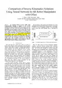
incoming pipes are introduced into the vessel in a fully automated manner by means of an appropriate manipulating and handling device. However, the take-out of coated pipes from vessel is done manually, namely, by a human worker (5), who makes use of a special hook (6) to place zinc-coated pipe on the conveyor (7). This operating stage of steel pipe making process has been observed to be a bottle-neck for the production control system and to affect considerably the execution of process planning. This research was aimed at finding a design solution in order to replace skilled human operator (from this hazardous area) by a controlled robot arm that will imitate all the primitive operations he was doing. It was assumed that this manipulator shall be equipped with an appropriate gripper holding the hook from outside the molten zinc that will capture, take out and place the pipe on the output-transport conveyor. Therefore, the job-shop control and automation system has been re-designed, within a supervisory computer process control setup, by introducing a simple controlled robot arm to perform this mechanical sub-process. Only then the task-sequence planning and control can also be made fully automatic.
2.1 On zinc-coating sub-plant
2.2 Modelling Analysis of Manipulation Process and Task Control Design
One essential part of quality steel-pipe making production is zinc-coating partial process. This partial process is the finalising phase in the pipe production. Figure 1 (at the end of the text due to its size) presents the schematic of final part of zinc-plate coating plant witch consist of eight main components depicted in the figure. Pipes are coming in across portal beams (1) and the so-call loading star (2) in the vessel with melted zinc (1450oC). To bottom of the vessel, pipes are carried by means of especially designed downer (3). During this motion of pipes in the vessel these become covered with zinc, i.e. zinc-coated. Finally, every pipe must be pulled out and taken on the output transporting conveyor (7). Currently, the
The manipulating operation process represents a cycle of a set sequential, primitive, mechanical motion operations as well as grasping and placing, and their cyclic repetition during the operation of zinccoating plant according to the supervision operated schedule of pipe production line [16] followed by extensive sequential communications [7], [20]. Figure 2 depicts graphically this cycle of mechanical manipulation operations. This process is an inherently computer-supervised, discreteevent dynamic process [14], [6], [20] and so is the overall automation system of job-shop control [2], [6], [8], [9]. It should be noted, however, that mechanical manipulating subprocess of zinc-coating plant has a crucial
impact on both productivity and throughput of the entire production line as well as on its reliability [16].
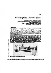
Fig. 2. A graphical representation of the manipulator robot work cycle
Conditionally, taking by presumption that starting operating position of the manipulator were at point 0, when hook is at the height of 200 mm from the operating horizontal plane, the modelling analysis has yielded the linguistic model of one full cycle of the manipulation and handling process. This model, in more detail of operational sequence of primitive events [4], [8], [15], is described as follows: 0. Initial state – by definition – the initial position and status of the manipulator, the 0th state, is the angular positioning at zero angular degrees relative to the horizontal line and with empty hook-gripper adjusted in parallel to the wall of zinc-vessel. 1. Task of vertical motion into the vessel, sliding by its wall, for 1000 mm linearly to reach the lowest allowable position from the vessel bottom beneath the pipe to be handled. 2. Task of left-revolute motion of about 100 angular degrees so that the hook-gripper grasps the pipe (at the left-ending approximately) during the 0-90 degrees of rotation, and then by means of the additional rotation hook-gripper clasps the pipe firmly (to prevent it sliding back during the pool-out). 3. Task of vertical motion out of the vessel for 1000 mm linearly with the pipe griped so that it gets to the position of about 300mm above the vessel.
4. Task of short motion to the left of the vessel so as gripped pipe to reach the coordinate of magnetic roller pair of the automated outputtransport carrier. 5. Task of vertical motion dawn so as the left-ending of the pipe be ‘lied dawn’ on outputtransport carrier so that the pipe is clasped and simultaneously the hook-gripper released, which is combined with additional short motion dawn nearby the entrance to the output-transport carrier to reach the position of about 200mm above the vessel. 6. Task of right-revolution of the emptied hook-gripper for about 100 degrees so that the hook-gripper gets to 0 degrees relative to the horizontal in parallel to the zinc-vessel wall. 7. Task of short motion of the emptied hook-gripper under zero-angle relative to the horizontal (opposite motion to the one in step 4) in order to return back to the initial state of the manipulation state, when the cycle is restarted.
Location of the robot manipulator will be near to the left side of vessel and to a distance of about 600mm from the outputtransport conveyor. The dimensions of produced pipes to be zinc-coated are the standard ones, i.e. ½”, ¾”, 1”, 5/4”, 6/4”, 2”, 21/2”, and 3”, and these have been observed with regard to hook-grippers needed.
3 On Task Sequences, Fuzzy-rule Knowledge Bases and Petri-net Systems In manufacturing engineering, either in design and development or in implementation and operation problems, the underlying nature of the aspects and issues involved requires to deal with discrete either stochastic or event driven processes, or both [2], [3], [5]. In either case, from the points of view of control, management decision and coordinating supervision, by and large, the information flow within the system takes the form of process and task and control sequences that may satisfy the so called Markovian property, which guarantees the next state of the system to depend on the previous one only and not on the entire pre-history. Most often, Markovian property is satisfied by systems of concern, and this is certainly the case with steel-pipe production line in this paper, thus giving rise to the triple paradigm of the system
concept: real-world system, its conceptual model and its mathematical representation models [3]. Insofar, a number of approaches to modelling representation and control have been developed in the literature and applied in industrial practice. The underlying nature of steel-pipe manufacturing process and its supervisory jobshop control is dominated by their respective discrete-event dynamics, and therefore Petri-net and fuzzy-Petri-net are the appealing formalisms to apply.
3.1 On Petri-net and Fuzzy-Petri-net Formalisms Petri-net formalism itself is a derivation out directed-graph formalism invented and was first invented by Karl Adam Petri (1956) in his doctoral dissertation on communications between automata, which was soon extended to computer networks and thereafter to manufacturing and telecommunication systems and the to many other fields of engineering and science. In linguistic modelling terms, a Petri net, PN, is a bipartite (special kind of) directed graph, PNg, together with an initial state called the initial marking, M0, and a fundamental rule called the rule for transition enabling and firing (Murata [14]). The underlying graph PNg is a directed, weighted, bipartite graph consisting of two kinds of nodes, called places (graphically, circles) and transitions (graphically, bars or boxes), and directed arcs interconnecting them such that arcs are either from a place to a transition or from a transition to a place. Arcs are labelled by positive integers of their weights such that a qweighted arc denotes a set of q parallel arcs (labels for unity weights are omitted). A marking, representing the PN state, assigns to each place in the PN a non-negative integer number k; if a place p is assigned non-negative integer k it is said that p is marked by k tokens. A marking (state) of a PN model is denoted by M, an mvector, where m is the total number of places in the PN model, and the p-th component of M, denoted by M(p), is the number of tokens in place p. In conceptual system modelling by means of the concepts of conditions and events, places represent conditions and transitions represent events. For discrete-event processes of concern, it may be argued in favour of so-called predicate/transition nets. It is known [8], that in
many of the previous works on predicate/transition nets there have been developed approaches to handling predicate expressions in systems modelling with high-level Petri nets for event-driven systems and task sequences. Tokens in predicate/transition nets can be structured objects carrying values, and transition firing can be controlled by imposing conditions on the token values. The major difference between predicate/transition nets and fuzzy-Petri nets, however, is that a fuzzy-Petrinet model can represent more generalized information using fuzzy numbers and complex fuzzy reasoning functions as well as linguistically generated models [2], [3]. This is why fuzzyPetri-net models can cope with the difficult problem of choosing feasible task sequences, which is the ordering synthesis of the correct precedence relationships among all important events or transitions. Hence Petri-net [9], [14] and fuzzy-Petri-net [1], [2], [4], [5] representations offer more adequate tools for problems in manufacturing engineering, and these are used in the representation modelling and design of task-sequence control in the current investigation work. A considerable number of articles concerning fuzzy Petri nets or other similar nets encompassing properties of both Petri-net (Murata [14]) and fuzzy-system (Wang [19]) formalisms have been published during the last decade. Fuzzy sets have been used as a broad conceptual framework for dealing with uncertainty and information. For a given universe of discourse X, which contains all the possible elements of concern for a particular application, the crisp set is defined to dichotomize X to two groups: members (those that belong to a subset A) and non-members (those that certainly do not). Because of vagueness in dividing members of the class from non-members, a fuzzy set is introduced by assigning to each possible individual in X a value representing its grade of membership in the set. Now, for a work-piece handling and manipulation robot, during the manufacturing process of turning the piece into (semi)product that is represented by the respective discreteevent Petri-net model, the grade of membership of the object, (semi)product, would gradually increase. Therefore, this grade corresponds to the degree to which the partial product of a given (semi)product is similar to the concept of the
actual (semi)product. Larger values denote higher degrees of membership of the system object. A global fuzzy state of the system is thus defined as a mapping from the objects in the system to a set of membership functions defined for each object, or subsets of objects. More recently, in the course of investigation of a fuzzy-Petri-net reformulation of Saridis’ organising controller [15], following Looney’s results [13], Dimirovski [4] has developed another mapping procedure also involving a fuzzy-rule-chaining reasoning, that generates an adequate fuzzy-Petri-net model (FPN) associated to a pre-designed fuzzy-rule knowledge base (FKB) for a class of robot manipulating tasks. In this work, fuzzy-rule knowledge base is mapped onto a Petri-net (PN) representation model by means of appropriate association of the respective propositions in FKB and of the truth degrees, which make up the essence of the FKB, with the PN places and the PN transitions, respectively, by means of a bijective function (to ensure a compatible and consistent linkage of both formalisms). For, the proper association of between the generic elements in both formalisms, such as propositions, linguistic variables of truth, function of truth, degrees of fulfilment, and the implication relationship versus places, transitions and marking function in the PN framework, is crucial. In particular, the truth function assigns to each PN transition a linguistic fuzzy truth value the degree-of-fulfilment of which is governing the FPN marking function. Since the mapping procedure involving the data-driven reasoning algorithm of fuzzy-rule-chaining with a degreeof-fulfilment and fuzzy possibility distributions, which generates fuzzy-Petri-net model associated to a pre-designed fuzzy-rule reasoning production schemata, this FPN representation model is considerable general fuzzy Petri net. Similarly, also following Looney’s results [13], Cao and Sanderson in their recent works [1], [2], however, introduced a specific definition of the generalized fuzzy Petri net, which incorporated three types of fuzzy variables: local fuzzy variables, fuzzy marking variables, and global fuzzy variables. Property analysis associated with some typical cases of fuzzy Petri nets was given too. Hence both these definitions of fuzzy-Petrinet models of discrete-event processes can also be applied to other kinds of applications including artificial intelligence, knowledge based systems, and automated manufacturing. The
associated Petri-net representation of fuzzyknowledge base and other systems also possesses the useful properties of liveness, safeness, and reversibility, and may be decomposed to lower level nets while retaining these properties.
3.2 On Representation of Robot and FMS Task Sequences Following A.C. Anderson [1], [2], [8] all manipulator robot task sequences in discreteevent manufacturing processes can be described in terms of three generic task sequences: assembly; disassembly, and internal-state transition. In our research in modelling and control of manipulation robot task sequences [16], we have found that their analysis and arguments are rather instrumental, and give a brief outline in here. From the task sequence planning point of view, the system must follow a partially ordered sequence of intermediate states to reach from the initial state to the final state, where state is defined as the vector of the states for all components in the system. It is assumed that the underlying systemic structure consists of n components, C1, C2, ..., Cn, where Ci represents the ith component. s(Ci) is used to represent the state of component Ci at a given time, assuming a discrete time representation. Each component may occupy a fixed number, Ni, of feasible states. The integer vector representation for the system state is Sj = (sj(C1) sj(C2) ....sj(Cn))T , 0 ≤ j ≤ M, and M+1 is the maximum number of all feasible states the system may occupy. In this approach, a partially ordered list of state vectors may be used to represent a task sequence. An operator or the job-shop control system will change the state of the system by making a set of components change from one sub-state to another sub-state, where a sub-state is defined as S’j = (sj(Cp1) sj(Cp2) ....sj(Cpr ))T and {sj(Cp1) sj(Cp2) ... sj(Cpr )} ⊆ {sj(C1) sj(C2) ... sj(Cn)}. The concept of a sub-state is introduced because many tasks may be thought of as functioning on several objects, i.e., a subset of the objects in the system (see [2] for full detail). The three fundamental kinds of tasks, T1, T2, and T3 are defined as follows: (1) Assembly: One set of components or subassemblies are combined with or put in geometric contact with one or more other sets of components or subassemblies
T1({Oi1,, Oi2, ..., Oiu })={{Cj1, Cj2, ..., Cjr }}, (3.1) where: Oik = {C1(ik) , C2(ik) , .... , Cnk(ik)}, Oik ⊆ {Cj1, Cj2, ..., Cjr } , 0 ≤ k ≤ u, Oik1 I Oik2 = ∅ , 0 ≤ k1 , k2 ≤ u. (2) Disassembly: A subassembly or assembly is separated into a set of components or subassemblies T1({{Ci1, Ci2, ..., Cir }}) = {Oj1, Oj2, ..., Ojl}, (3.2) where: Ojk = {C1(jk), C2(jk), .... , Cnk(jk)} , Ojk ⊆ {Ci1, Ci2, ..., Cir } , 0 ≤ k ≤ l , Ojk1 I Ojk2 = ∅ , 0 ≤ k1 , k2 ≤ l. (3) Internal State Transition: The internal state of a set of components is modified by changing the relative geometric relations of the components, or by modifying a property of a component subset in this set where:
T3({Op}) = ({Oq})
(3.3)
which includes three types of fuzzy variables: local fuzzy variables, fuzzy marking variables, and global fuzzy variables. Local fuzzy variables are used to model the uncertainty of the local variables or internal states of objects; fuzzy marking variables are used to indicate the uncertainty that events have occurred; and global fuzzy variables are used to represent the characteristic variables of the global task. In this paper, since we discuss the task sequencing of operations sequences, only global fuzzy variables are used to model the degrees of completion for different global subtasks. Therefore, the following presentation of the definition of the fuzzy Petri net includes global fuzzy variables. The task sequencing problem is solved by imposing numerical constraints incorporated in the token values in the places. Similarly, the transition reasoning rules defined in the net also operate on the values carried by tokens. Definition 3: A fuzzy Petri net (FPN) with global fuzzy variables is defined as an octanary (8-) tuple FPN = (P, T, Qt, Iv, α, β, mt, µφ ),
(3.4)
Op = {s(Ci1), s(Ci2), ......, s(Cis), s(Cis+1), .... , s(Cis+d) , ......, s(Cir)} ;
where:
Oq = {s(Ci1), s(Ci2), ......, s′(Cis), s′(Cis+1), .... , s′(Cis+d) , ......, s(Cir)};
T = {t i, t2, … , tm} is a finite set of transitions, m ≥ 0, P∩T=∅.
Op - Oq = {s(Cis), s(Cis+1), .... , s(Cis+d)};
Qt = {q1, q2, … , ql} is a finite set of state tokens 1 ≥ 0.
Oq - Op = {s′(Cis), s′(Cis+1), .... , s′(Cis+d)}. As the number and complexity of the system substates and their interactions increase, which is not the case of robot-arm manipulation task sequence in this project (see Subsect. 2.2), the task representation may be further simplified by defining an appropriate feasible geometric state vector, which separates geometric state relations from internal state variables of individual objects. Using this representation, a set of mathematical functions can be defined for task planning and execution of manipulator robots, e.g, such as the one to be introduced at Kumanovo pipe manufacturing line, and transitions from one to another system state may be well determined based upon the properties of appropriately defined vectors in Eqs. (3.1)-(3.3).
3.3 On Fuzzy Petri-Net Representation of Discrete-event Processes Now, consider the definition of the generalized fuzzy Petri net (Cao and Sanderson [1], [2]),
P = {p1, p2, …, pn} is a finite set of places n ≥ 0.
Iv = {Iv1, Iv2, … , Ivn} is a set of internal state variables which are associated with corresponding objects or places. This mapping can be described as P→ Iv,. Global fuzzy variables are modified by changing internal state variables when the net is executed. ⊆ {P x T} is the input function, a set of directed arcs from places to transitions. We call each pi where (pi, tj) ∈ α as an input place of tj. ⊆ {T x P} is the output function, a set of directed arcs from transitions to places. We call each pi where (tj, pi)∈ β as an output place of tj. mt : QT → {α1,α2 ,…..αl-1, C} where αj=∪i{(ki,σki)}, 1≤j≤l-1 is a mapping from a token to 1) a union of 2-tuples of ki and the kith global fuzzy variable, σk, if one or more global fuzzy variables are attached to the token; or 2) a constant, C, which indicates no global fuzzy variable is attached. σk, is a membership function
with respect to the degree of completion in a universe of discourse. In the following discussion we will often refer to the value of the global fuzzy variable as the token value.
µf : T → {f1, f2, ... , fm} is an association function, a mapping from transitions to corresponding reasoning functions or rules. A reasoning function fi, ,maps a set of tokens in input places to another set of tokens in output places.
If a place pi, represents an object Oi, the kith global fuzzy variable within this place can be represented as σki(qj), where qj, occupies pi, in the current state. A global fuzzy variable is attached to a token. This is an m dimensional membership distribution function related to a characteristic variable of a global task. The global fuzzy variable may be used to sequence a set of transitions so that a global task can be completed. An example is the use of a global fuzzy variable to represent degree of completion of a task. The token value should increase during the execution to indicate correct sequencing of operations. Definition 4: Concept of a global fuzzy state Sg(p1, p2, ... , pn) = (σ(p1),σ(p2), ... ,σ(pn)), is an enary (n) - tuple of the global fuzzy variables in the FPN. σ(pi) (written as σi) is either a value of the token if this token is existing, mt(qj), or, e, indicating no token is existing. A transition in a fuzzy-Petri-net system may be enabled when the token values of its input places satisfy some specified fuzzy reasoning rule. For instance, one such reasoning rule for assembly requires the token values of all objects to be assembled have values not less than a threshold value or degree-of-fulfilment, and therefore be members of a designated level set [2], [4]. If a transition is chosen to fire, all tokens in the input places are removed and fuzzy tokens are added to its output places, which may contain values different from the input values. The values of new tokens will depend on the fuzzy reasoning rule of the transition.
4 Feasible Sequences in FuzzyPetri-Net Models and Linguistic RobArm Model It should be noted, in both robotic and flexible manufacturing systems control, care must be taken that job-shop control system executes feasible controlled sequences only. In the sequel
we quote without proofs the two main theorems that must be observed when investigating this issue. The first one is a fundamental theorem of the Arithmetic, while the second one is due to Cao and Sanderson [2].
4.1 On Two Theorems on Feasible Task Sequences The first one provides a method to use the feasible states obtained during the generation of the fuzzy-Petri-net model via search for feasible, complete, and correctly ordered sequences efficiently. Theorem 1: Fundamental theorem of Arithmetic. If pi, and qi are positive primes, and if n
m
i =1
j =1
a = ∏ piαi = ∏ q βj j
(4.1)
where: 1