Autopilot Project with Unmanned Robot. Bilgin Seçkina, Tuna ... This paper presents the hardware and the software parts of this robot. © 2012 The Authors.
Available online at www.sciencedirect.com
Procedia Engineering 41 (2012) 958 – 964
International Symposium on Robotics and Intelligent Sensors 2012 (IRIS 2012)
Autopilot Project with Unmanned Robot Bilgin Seçkina, Tuna Ayana, Emin Germena a
Anadolu University, Electrical & Electronics Eng Dept. Eskisehir, TURKEY
Abstract
Mobile robot is an important figure during the search and rescue application after the natural diseases such as earthquakes, fire, flooding. In the disaster areas, searching the sign of living bodies or investigating the ruins have critical roles in life saving. In most cases this operation is done remote controlled mobile robots. In this project a prototype of full featured robot has been developed in order to track the signs of lives in disaster areas. This mobile robot navigates through a planned route, avoiding from obstacles. During the navigation, it is capable of sending images of camera mounted on the robot where user can observe and track the environment. The GPS (Global Positioning System) module, infrared sensor, webcam, magnetometer, microcontroller and single board computer help routing and tracking processes. The host computer and mobile robot communicates through wireless channel. This paper presents the hardware and the software parts of this robot.
© 2012 The Authors. Published by Elsevier Ltd. Selection and/or peer-review under responsibility of the Centre of Humanoid Robots and Bio-Sensor (HuRoBs), Faculty of Mechanical Engineering, Universiti Teknologi MARA.
Open access under CC BY-NC-ND license.
Keywords: unmanned mobile robot; GPS navigation techniques; intelligent algorithms; wireless communication;image processing;
1. Introduction Nowadays although an excessive amount of effort has been spent in order to predict the natural diseases such as fire, earthquake, flooding, mine accidents, explosions, however recent technologies are rather incapable of getting to predict those in advance. Since those diseases are unavoidable, the crucial think is focusing on developing technological solutions on rescuing and research in order to save lives after diseases. Time is very crucial in the disaster areas and rescuers should always race with it. The ruins have to be searched without disturbance and narrow gaps have to be scrutinized rigorously. Unmanned robots have critical role during the investigation of the paths through sign of life. The aim of this project is designing a robot which is capable of targeting through special spot, equipped with the capabilities of sending images getting on the pathway, controlled with wireless communication. This unmanned robot navigates, avoids obstacles and tracks the targets, using GPS locator, a camera, infrared sensor, led illuminator, wireless communicator and magnetometer. All the hardware devices are controlled through a single board computer located inside of the robot. Here some brief descriptions: 1.1. Navigation Of Mobile Robot Navigation is defined as the process of controlling the movement of the robot from source to destination. In unmanned systems, by means of movement control mechanisms, the predetermined route has to be followed. Then the route planning has great importance and in this scope there are plenty of researches in literature. [1] [2]. Since the main aim of the project is designing a mobile robot to reach to the destination autonomously, one of the major problems is the definition of the optimal path between the source and the destination. Since the mobile robot has no map information, the only tool is tracking the environment during navigation in order to get rid of the obstacles on the pathway. In this paper smart algorithms are researched and applied about navigation for unmanned mobile robot.
1877-7058 © 2012 Published by Elsevier Ltd. Open access under CC BY-NC-ND license. doi:10.1016/j.proeng.2012.07.269
Bilgin Seçkin et al. / Procedia Engineering 41 (2012) 958 – 964
959
1.2. Avoiding Obstacles Since in autonomous systems, host cannot control the robot every time, it will be the task of the mobile robot to monitor the environment continuously. The robot has to track the obstacles and get rid of them without misleading through the route. Avoiding obstacles on the route is another challenging problem in literature there are several methods [3] [4]. In rescuing, however it is necessary to consider exceptions on route planning such as not ruining some definitive spots. The algorithms implemented in this project use the information gathered from sensors used in the robot provide obstacle avoidance in a safe manner. 1.3. Target Tracking There are plenty of image processing techniques for target tracking. In unmanned systems a predefined target has to be recognized. The target can be defined either as an image or as an object. Its specifications are given to the robot and when the robot identifies those specifications, controller part of the mobile robot starts the tracking algorithms. In order to target tracking, the mobile robot uses two servo motors connecting to a camera mounted in front of the robot. When the controller starts the tracking algorithms, servo motors monitors the object by changing the angle of the camera. Here target tracking is another capability of the robot. 1.4. Video Streaming One of the important natures of the robot presented in this paper is the ability of sending the images in real time using streaming method. Streaming methods are used to provide either video or data tracking both in server and client side of transmission. In mobile robot, webcam outputs can be observed from the host side using video streaming. This method has a lot of advantages in mobile robot systems. It is possible to observe the environment at the host side, and to redefine new jobs such as changing the route according to the identified object captured by the image set. Host computer can observe the environment of the mobile robot and also host computer can control the mobile robot manually using this method. In this paper, communication between the mobile robot and host computer is provided with wireless communication techniques. TCP is used for the streaming video transfer since control information also shared has great importance. Client and server side of TCP are created and video stream algorithms are implemented in the mobile robot [5]. The presented features should have to be explained from the point of view of both hardware and software. The next chapter describes the hardware units of the robot. The third chapter is dealt with the software run on different parts of hardware. The last chapter concludes the paper. 2. Hardware Specifications 2.1. Controller Units
Fig. 2. Single board computer unit The controller part of the mobile robot, which is shown in figure 2, consists of a single board computer (beagle board) and microcontroller. Beagle board [6] controls the peripherals, and interprets the data provided them. The autonomous target tracking and routing algorithms run on the beagle board which has 720 MHz processor, 2GB NAND memory and SD card slot. It enables to use an embedded operating system which enables multitasking. In order the control the robot through the host computer the wireless communication is provided through a wireless communicator connected to the beagle board.
960
Bilgin Seçkin et al. / Procedia Engineering 41 (2012) 958 – 964
On the mobile robot, it is used two Stellaris LM3S811 [7] microcontroller units equipped with 50MHz 32-bit ARMCortex M3 processors. The ARM based microcontrollers are the popular ones since they provide computational power but less power consumption. Also their flexible coding techniques because of Thumb-2 feature attract the attention. On both controllers, there are 6 PWM (Pulse Width Modulation) channels, 3 ADC (Analog To digital Converter) channels, 2 UART channels and an I2C channel. The UART (Universal asynchronous receiver/transmitter) communication technique provides data and control information exchange with the beagle board.
Fig. 3 First microcontroller unit
Fig. 4. Second microcontroller unit
The Pololu Motor Driver module [8] is used to control the movement of the robot. The first microcontroller unit which is described in figure 3 controls infrared sensor and direction of the mobile robot. Infrared sensor data is taken from ADC unit and interpreted. When an obstacle is detected on the pathway, the microcontroller sends this information to the beagle board. The beagle board in this very moment of time starts to interpret the data and locate it. In order to get rid of the obstacle the redirection operation is started and the beagle board sends the necessary information to the servo motor control structure. The servo motors serve to change the direction of the robot which is controlled by GPIO (General Purpose Input Output) pins of microcontroller. The Second microcontroller unit has shown in figure 4 controls magnetometer, GPS module and movements of webcam. Magnetometer data is taken from the microcontroller and heading is evaluated. I2C (Inter-Integrated Circuit) communication technique between magnetometer and mobile robot is used to track the data. GPS module sends the NMEA information to the microcontroller. Microcontroller interprets the data and send through the beagle board. Again UART is the main protocol between the controller unit and beagle board. After beagle board process the data, the navigation can be provided by first microcontroller unit. 2.2. Sensor Units
Fig. 5. GPS Module Design
Fig. 6. Dynamic sensor system
Sensor units are composed of the, infrared sensor, GPS module, magnetometer and the webcam. The webcam is used in order to get the images from the environment and send them to the Beagle Board through the USB channel in 15fps. It is placed on the front side of robot. Magnetometer is used to track the heading information of the mobile robot since it has an important role in autonomous navigation in order to interpret the navigation direction. GPS module is used to determine the
961
Bilgin Seçkin et al. / Procedia Engineering 41 (2012) 958 – 964
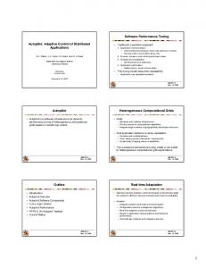
exact location of the robot. In order to use an active antenna and assisted GPS features, hardware is designed and connected on to the second controller unit. The unit pictures can be seen in figure 5. In this project also a dynamic infrared sensor system has been designed and used in order to provide to determine obstacle’s angle according to the mobile robot. The unit pictures can be seen in figure 6. Infrared sensor is connected to the servo motor and if an obstacle is detected, its position can be identified by microcontroller using the information from the servo motors of the sensors.
b’ stellaris LM3S811
servo 60°
Web cam servos
beagleboard
Usb hub
Web cam
a’ b
Motor driver
magnetometer
30°
gps
stellaris LM3S811
Wifi module
a
Fig 7. Dynamic sensor system & General placement
2.3. Power Unit A power supply unit for robot, which supplies power to actuators of the robot, installed between two Plexiglas plates. The unit is composed of 2S2P cells which are slim, light weight batteries based on the Polymer Lithium Ion chemistry. Total battery pack outputs nominal 7.4 V 17 Ah. which is capable of providing uninterrupted power to robot in 4 hours. 3. Software Specification The embedded system run on the beagle board is UNIX based system, The host computer which controls the robot and tracks the streaming video, the C++ is preferred since it provides and facilitates multitasking threads. Here the main part of the software is described. 3.1. Navigation Of Mobile Robot Although it is not given location map to the mobile robot, it is necessary to identify and localize the destination and construct the path in an optimum way. Algorithm is based on heading and current location data. Beagle board interprets the difference between target and current location data, and moves the robot through to the target using heading information. Mobile robot rotates itself to the target heading using magnetometer. After necessary rotation, mobile robot starts to move. The autonomous moving algorithm uses essentially four cardinal and four semi-cardinal directions in order to provide steady robot heading. Robot uses semi-cardinal directions after starting the algorithm until it reaches either longitude or latitude tolerance borders as seen in the figure 8. In the tolerance areas also, robot continues its movement using four cardinal directions.
962
Bilgin Seçkin et al. / Procedia Engineering 41 (2012) 958 – 964
GPS module has an error range at most 2.5 meter diameter. Since it causes heading calculation problem, accurate rotation to the target point may sometimes be a problematic issue. However during the movement of the robot through target, if no obstacle is encountered, the calculation process is repeated several times in a periodic fashion from the very beginning of the algorithm itself, in order to reduce the error.
Fig. 8. Rotating to the targe 3.2. Avoiding Obstacles Avoiding obstacles on the path is another challenging issue. There are several algorithms in the literature to get rid of the blocks and find the correct route. Here an intelligent algorithm has been developed and adapted to the robot. According to the algorithm, if the robot tracks an obstacle in front, first it will search a possible free path first on the right then on the left. In figure 9 it is explained to search a free path on the right. If it is found, the robot will move backwards than go through the right direction. Here in this very moment of time the robot and obstacle position is described in figure 10. The robot will go through this obstacle until free path at the left is deduced. After the free path has been found at the left, immediately the robot turns its direction through the target point. It is possible to be locked in dead end during the routing. In this kind of situations the robot moves backwards searching either freeway on the left or on the right. This iterative method helps to get rid of any kind of the obstacles on the path.
Fig 9. Avoiding Obstacles
Fig 10. Searching freeway on the left
Bilgin Seçkin et al. / Procedia Engineering 41 (2012) 958 – 964
3.3. Tracking Objects In order to track the object, the algorithm has been written in C++ using OpenCV image processing open source library. Tracking is provided by Lucas Kanade algorithm which is widely used method for optical flow estimation [9] which is a used for estimating motion of objects across a series of frames. During tracking process it is possible to locate a point on area which is captured by robot and sent to the host computer. This location is immediately interpreted and its coordinates are calculated and resent to the mobile robot through wireless. Since the robot is moved through its pathway, the relative position of the point is changed. These alternated positions are recalculated and the servo motors of the webcam are directed to this spot continually. With this facility, it is provided to track either movable or stationary objects while robot is moved. Also there is an option in the host that it is possible to redirect the robot to the movable objects. 3.4. Wireless Communication The controller part of the mobile robot, which is explained in figure 11, consists of a wireless modem. Communication between wireless modem and single board computer is provided by USB to Ethernet converter. The wireless modem connected to beagle board enables host computers to communicate through wireless. Here it is used Secure Shell (SSH) protocol to communicate with the mobile robot in an authenticated fashion.
Fig 11. Wireless communication 4. Conclusion The improvements in technology facilitate the search and rescue in the disaster zones. In most cases the area composed of several narrow passages which are difficult to move. In those kind of situations, small flexible unmanned robots help a lot. In this work this kind of robot has been developed. The robot consists of several hardware parts and software blocks. Those parts are explained with their usage. The path finding using GPS, tracking objects, obstacle avoidance are implemented on a prototype robot. It has been observed that the full featured robot which is designed and implemented in this project can easily be modified and new functions can be adapted. References [1] JasminVelagic;BakirLacevican;NedimOsmic “Efficient Path Planning Algorithm for Mobile Robot Navigation with a Local Minima Problem Solving”. Industrial Technology, 2006. ICIT 2006. IEEE International Conference on 15-17 Dec. 2006 [2] Zeng Bi;Yang Yimin ;Xu Yisan “Mobile Robot Navigation in Unknown Dynamic Environment Based on Ant Colony Algorithm”. Intelligent Systems, 2009. GCIS '09. WRI Global Congress on 19-21 May 2009 [3] Zeng Dehuai ; Xu Gang ;Xie Cunxi ;Yu degui “Notice of Violation of IEEE Publication Principles Artificial Immune Algorithm based robot obstacle-avoiding path planning”. Automation and Logistics, 2008. ICAL 2008. IEEE International Conference on 1-3 Sept. 2008
963
964
Bilgin Seçkin et al. / Procedia Engineering 41 (2012) 958 – 964
[4] Baturone I. ; Gersnoviez, A.A. “A Simple Neuro-Fuzzy Controller for Car-Like Robot Navigation Avoiding Obstacles”. Fuzzy Systems Conference, 2007. FUZZ-IEEE 2007. IEEE International 23-26 July 2007 [5] Meng Guo ; Ammar, M.H. ; Zegura, E.W. “a vehicle-to-vehicle live video streaming architecture”. Pervasive Computing and Communications, 2005. PerCom 2005. Third IEEE International Conference on 8-12 March 2005 [6] http://beagleboard.org/static/BBSRM_latest.pdf [7] http://www.ti.com/general/docs/lit/getliterature.tsp?literatureNumber=spmu030b&fileType=pdf [8] http://www.pololu.com/catalog/product/1212 [9] Lee Yee Siong ; Mokri, S.S. ; Hussain, A. ; Ibrahim, N. ; Mustafa, M.M. “Motion detection using Lucas Kanade algorithm and application enhancement” Electrical Engineering and Informatics, 2009. ICEEI '09. International Conference on 5-7 Aug. 2009