BASIS FOR MICRO-FACTORY: CNC MICROMACHINE TOOLS L. Ruiz-Huerta Laboratory of Mechatronics, Instrumentation Center, National Autonomous University of Mexico. Circuito Exterior S/N, Cd. Universitaria, Coyoacán, 04510, A.P. 70-186 México, D.F. e-Mail:
[email protected]
Abstract--The problem of development micro-factories is discussed. Micro-factories can help to reduce the consumption of resources (energy and materials), and space; can help to increase productivity. We propose to use micro machine tools (CNC), to create micro-cells of production. The base feature of micro-factories is the flexibility of production. Main requirements to micro CNC machines tools and control systems are described as well as prototypes of the developed micro machine tools and testing results are presented. I. INTRODUCTION The size of a micro-factory depends not only on the size of the factory equipment; depends on the size of the products too. The principles for flexible manufacturing (cells) of micro factories, could be use in micro-mechanics and micro-factories. At present, small size mechanical devices are produced by equipment, which demands large rooms, large amount of energy and high labor cost. Modern microelectronics and control devices permit to create fully automated micro mechanical equipment corresponding to de size of produced devices and finally -fully automated micro-factories (desktop factories). They will produce low cost micro mechanical devices [1]. We know two possible ways for micro-factories creation. First way, is to use modern micro electronic technology for manufacturing low cost micro details of sub-millimeter sizes, and the second, to use conventional technology of mechanical treatment of materials by low cost
micro mechanical CNC equipment (micro machine tools, micro assembly devices, micro testing devices etc.)[1]. The first approach is used very widely for manufacturing micro sensors and micro actuators [2,3], but it has some limitations connected with the problems of 3-D details manufacturing. Very difficult problems present also automatic assembly of micro devices, because 2-D details have no special surfaces, which facilitate assembly process. The second way has no such problems, but demands low cost micro equipment, which is absent at present. In the [5] main principles of such equipment creation are proposed. Micro mechanical equipment is to be made as a sequential generations of micro machine tools and micro assembly devices. Each next generation must have smaller sizes than previous one and must be produced by the equipment of previous generation. II. THE MAIN REQUIREMENTS TO THE MICRO MACHINE TOOLS
At first, the micro machine tools must be sufficiently (but not superfluous) precise. We consider the first generation of micro machine tools as the equipment for producing details having overall sizes from some hundred microns to some millimeters. In this case they must provide tolerances of some microns [1] Developed micro machine tools, at least the machine tools of first generation, must be multifunctional. The simplest multifunctional micro machine tool must have 4 or 5 degrees of freedom (DOF) 3-translation axis and 1 or 2
rotary axis. Micro machine tool must use the simplest types of stepping motors and the simplest sensors. It's preferable not use industrial motors and sensors, because the future next generation micro equipment will demand the possibility of producing all the components of micro equipment using the same micro equipment.
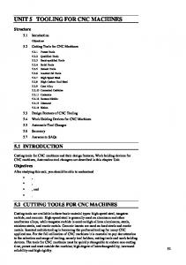
(12) with cutter and two parallels metal pins for measurement of turned work piece diameter. By milling and drilling special gripper for workpiece should be installed on the carriage (7). The mayor components of the MMT are made in brass and aluminum. 9
6
It's important to ensure the simplicity of manufacturing and assembly of micro machine tools. For this purpose all the complementary components of the machine tool must be as simple as possible.
7
8
For mass parallel manufacturing process which will decrease amount of human labor it's necessary to develop such a system of sensors and such a control system which facilitate combining of huge number of micro machine tools in the frame of desktop micro factory, controlled by one operator. III. STATE OF THE ARTS IN THE MICRO MACHINE TOOLS DEVELOPMENT
Mechatronics Lab. had developed and tested some prototypes of first generation machine tools. The main idea was to make prototypes as simple as possible, and to use minimum of industrial components, for scaling down developed micro machine tool in future generations. A. CNC Prototype The prototype is shown in the figure 1. On the base (1) the guides (2), (4), (6), for 3 carriages (3), (5), (7) are installed by the sequential scheme, i.e. each subsequent guide is installed on the previous carriage for to provide translation movements along the axis X, Y, Z. The spindle case (10) with spindle (11) also is installed on the base. The drives for carriages and for spindle use stepping motors (8) with gearboxes (9). The spindle has clamp for to grip workpiece by turning, drill by drilling or mill by milling. Support
3
10
2 11
1
4
5 5
12
Figure 1. CNC Micro Machine Tool. 1) Components The main components of the prototype are: 1. Stepping Motors. We make our stepping motors with 4 steps per revolution and they can be forced to make 8 half steps. They are used in the mode of high-speed rotation. 2. Carriage. The guides for carriage were made as the round bars. It simplifies the manufacturing, assembly and scaling down processes. For reasons of robustness we decide to include some ball of bearings compensate errors of guide’s adjustment. 3. Transmission. It includes leading screws and gearboxes to reduce the speed of motors and increase the torque. All translation axes include the same configuration (reductor, screw, stepping motor). 2) Control The feedback from the machine tool to the personal computer was realized on the base of four contact sensors, three of them are used to
determine home position of the carriages, and one is used to determine the moment of the contact of any tool with workpiece. This contact we used for determining relative positions of different instruments needed for the whole manufacturing process, and for measurements in the manufacturing process. We use electrical contact sensor and could have the feedback only from metal workpiece. If we need to make details from plastic, we made at first the same detail from metal, and then repeated the manufacturing process with plastic workpiesces. In principle it is possible to use other types of contact sensors (for example, acoustical contact sensor) to treatment of workpieces from any materials. The control system, acquire the signal check of sensors, using the PC´s parallel port. In order to get the control of the MMT, we assigned a specific task for the A port (sends data form PC to MMT); the B port (receives data form sensors and motors); and, finally the C port (gives the control signals to the system). The second prototype of control system is showed in the fig. 2.
and Y-axis has 35 mm. All of them have the same configuration. The resolution is 1.9? m per step of motor. B. Test Pieces Examples of the pieces that could be manufactured with this MMT are showed in figure 3. Those photos are compared with a match head. The sizes of the devices are showed in the table 1.
Figure 3. Test Pieces The minimal sizes of pieces are investigated now. The main goal of this MMT development were the low cost of hardware and the relative easy to reduce its sizes in future for new generations of machine tools with low dimensions. Actually we are working in applications (micro filters, micromanipulators, etc.), and in new prototypes of MMT. Description
Fig. 2. Control System 3) Description The MMT has 130? 160? 85mm, and is controlled by PC. The MMT, has three translation axes (X, Y, and Z), and one rotational. The axis X and Z, have 20 mm of displacement,
External diameter Internal diameter Number of teeth Head Diameter Screw Diameter
Theory Value
Gear 1700? m 800? m 12 Screw 1580? m 800? m
Real Value
1695? m 802? m 12 1585? m 796? m
Deep of spiral Total longitude Spiral Longitude Spirals per mm.
30? m ------7.2 Worm Screw Screw Diameter 2600? m Deep of spiral 650? m Total longitude ---Spiral Longitude 2500? m Spirals per mm. 1 Table 1. Test pieces values.
32? m 3290? m 1185? m 7.24 2610? m 645? m 3300? m 2610? m 1.15
IV. DISCUSSION We proposed to use downsizing of conventional mechanics, with simple details, to reduce the cost. At first, we developed one MMT, with possibilities to milling, turning, etc. This MMT is the basis for develops larger structures of manufacture (cells, modules, factories, etc.). We consider that the basis for cheaper devices is parallel productions with low cost equipment. The low cost equipment is possible if we design simple hardware with possibilities to downsizing. To increase the potential of this MMT, its necessary to developed new systems of control and configure the first prototype of micro cell of production. This cell could contain at least two MMT and one or two manipulators. This configuration will help us to manipulate materials (and products), to perform an assembly processes. V. CONCLUSIONS We propose to make the micro factories on the base of miniaturized mechanical equipment. Such equipment permits to preserve all the types of existing mechanical technologies, manufacture the details of any shape and use any materials. Small sizes of equipment make it possible not only save the room, energy consumption and materials, but permit also to use relatively low precision equipment, because absolute tolerances decrease
with decreasing of equipment sizes. Low cost of micro equipment will permit to organize mass parallel production of micro devices at the micro factories. To obtain low cost micro equipment it’s necessary to make it in the form of sequential generations. Each generation has the sizes smaller than previous one, and is to be made with previous generations of equipment. VI. ACKNOWLEDGEMENTS. Special thanks to Professor Dr. Ernst Kussul and Alberto Caballero-Ruiz by your support in this work. This work was supported by CONACyT project 339944-U and DGAPA UNAM project IN-118799 VII. REFERENCE [1] Kussul E., Ruiz L., Caballero A., Kasatkina l., Baydyk T; CNC machine tools for low cost micro devices manufacturing; First International Conference on Mechatronics and Robotics; St.Petesburg, Russia; 2000, Volume1; pp 98-103 [2] Various authors 1987-1996 Proc. IEEE Mechanical Systems Workshops (IEEE) [3] Gabriel K J 1994 ARPA MEMS Program. Vision Statement (ARPA/ETEO) [4] Micromachine Center Japan 1994-1995 Introductory. Course Micromachine No. 7-13 [5] E Kussul, D Rashkovskij, T Baidyk and S Talayev, 1996, Micromechanical engineering: a basis for the low- cost manufacturing of mechanical microdevices using microequipment, J. Micromech. Microeng. 6 410-425. [6] Microfactory; 2nd International Workshop on Microfactories, Fribourg, Switzerland, Octubre 9-10, 2000, Swiss Foundation for Research in Microtechnology.