Ashley Stroupe, Terry Huntsberger, Avi Okon, Hrand Aghazarian, Matthew Robinson ..... Magnone, and Mike Garrett for supporting RCC platforms.
Behavior-Based Multi-Robot Collaboration for Autonomous Construction Tasks* Ashley Stroupe, Terry Huntsberger, Avi Okon, Hrand Aghazarian, Matthew Robinson Jet Propulsion Laboratory / California Institute of Technology 4800 Oak Grove Drive, Pasadena, CA 91 109 [Ashley.Stroupe, Terry.Huntsberger, Avi.Okon, Hrand.Aghazarian, Mutthew.Robinson)@jpl.nasa.gov Abstract - The Robot Construction Crew (RCC) is a heterogeneous multi-robot system for autonomous construction of a structure through assembly of Long components. The tworobot team demonstrates component pIacement into an existing structure in a realistic environment. The task requires component acquisition, cooperative transport, and cooperative precision manipulation. A behavior-based architecture provides adaptability. The RCC approach minimizes computation, power, communication, and sensing for applicability to space-related construction efforts, but the techniques are applicable to terrestrial construction tasks. Index Terns - space robotics, manipulation, muEti-robot systems.
I.
cooperative
mobile
INTRODUCTION
The current NASA roadmap calls for a human Lunar presence by 2020, followed by human Martian exploration [SI. For safety, these missions require prior placement of infrastructure (habitats, power, oxygen, etc). Robotic technologies must perform site clearing and leveling, component transport, placement, and docking, and structure inspection and repair. Communication delays and blackouts require that much of the robotic construction be autonomous. Launch and space operations constraints require systems to minimize mass, volume, and power while remaining robust to uncertainty and errors. This paper presents early results for Robotic Construction Crew (RCC) in a construction scenario including cooperative component grasping, transport, and precision placement by a heterogeneous team. To accommodate space-driven constraints, our approach minimizes sensing, computation, and communication. By design, the distributed behavior-based control approach that tightly couples current sensing with execution eliminates the most processing-intense tasks such as mission planning and optimal task-decomposition. The rovers use a completely distributed control approach during independent operations, During team tasks (cooperative transport and manipulation) rovers use a synchronized leader-follower approach with centralized decision making and distributed execution to maintain tight coupling of team members. The Robotic Construction Crew has demonstrated reliable capabilities of component acquisition, transportation, manipulation, and placement in an outdoor-like laboratory environment. While primariIy developed for planetary habitat construction, these capabilities are also applicable to Terrestrial construction activities.
* This work was carried out at the Jet Propulsion Laboratory, California Institute of Technology. under a contract with the National Aeronautics and Space Admmistration.
11.
BACKGROUND AND RELATED WORK
Current state of the art in autonomous construction provides for simple mating of marked components in a laboratory setting with a flat floor. Carnegie Mellon University has demonstrated multiple component mating using three specialized robots [vision, coarse manipulation, fine manipulation) [2][13]. The vision robot aligns where it can see the necessary work space and tells the manipulator robots how to adjust for alignment. Work in cooperative transport has primarily focused on cooperative pushing behaviors on flat floors [3][9][10][12][16],including some approaches that use the transported object to communicate implicitly. Most work in cooperative manipulation with force feedback focuses on fixed-based manipulators 171. A robot has also stacked masonry blocks [ 1 11. To transport rigid components cooperatively with tight grasp, the robots must simultaneously maintain a formation. Most formation work applies potential fields using vision and / or explicit communication [ 1][4][5]. JPL has demonstrated cooperative transport and deployment of large components in an outdoor environment [6][15]. To date, no work has demonstrated end-to-end grasping, transport, and precision placement of a rigid component into a fixed structure by an autonomous team. RCC demonstrates these capabilities in an outdoor-llke laboratory setting.
111. TASKDESCRIPTION
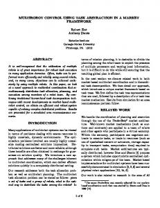
A. Environment The structure is a set of interlocking components. The team must obtain components from a storage unit, transport them to the construction site and place them into the structure. Structure components are aluminum beams (180 x 12.5 x 12.5 cm) with cones that interlock with the beam above. At each end is a grasping point, a cylindrical channel through the component. Three fiducials mark each grasp’s location. Fig. 1. shows the structure and a component end in detail.
fig. 1. The structure of interlocking beams. Inset Component end with three fiducials and two interlocking cones.
The SRR and SRR2K rovers (Fig. 2) comprise the heterogeneous team. Each has four steered wheels and a unique four-joint manipulator arm. Rovers are equipped with on-board wireless modems, computing, and battery power.
Action Behaviors Fig. 2. SRR (left) and SRR2K (right) rovers
3. Sensing
One pair of stereo cameras is at the front of each robot to provide three-dimensional visual sensing. Stereo calibration uses Hybrid Image Plane/Stereo (HIPS) [In preparation for publication]. HE'S generates camera models through direct visual sensing of the manipulator's end-effector in conjunction with end-effector position estimation by manipulator kinematics. By correlating manipulator kinematic position with three-dimensional position, manipulator placement accuracy improves by approximately a factor of 2.5 over traditional calibrated stereo. If run online (not done in this work), continued adaptation of the manipulatorkamera models improves placement by up to an additional factor of five and can account for changes in system configuration and ensure consistent precision for the life of the mission. Each manipulator has a three-axis force-torque sensor positioned at the wrist to sense forces and torques imparted by the component on the manipulator. This provides passive communication between the rovers about relative team and load positions during cooperative transport, which is not observable through the forward-facing cameras.
IV.
APPROACH
A. Overview The overall architecture is CAMPOUT, a behavior-based multi-robot control architecture 161. CAMPOUT provides commands to a real-time control system performing low-level actuator and sensor control. The overall construction task is decomposed by hand into a series of subtasks. These subtasks are in turn composed of general, reusable complex COMPOUT behaviors which are composed of simple platform-specific control and sensing behaviors.
B. Subtasks The Construction task calls a series of subtasks, each designed to execute one stage of the construction task. Successful completion of each subtask by the team triggers transition to the next subtask. Fig. 3 illustrates this sequence and shows the partial behavior hierarchy For cooperative tasks, leader-follower control with action synchronization ensures common action selection, parallel action execution, and team recognition of success and failure conditions.
Fig. 3. Executron begins with Align at Storage and completes after Place Component. Two-levels of the behavior hierarchy are shown. Large ovals are subtasks and small ovals are complex behaviors (sensing and ac'non)
Several subtasks require that the team (independently or cooperatively) align relative to the visual cues. Due to sensing uncertainty and motion uncertainty, executed motions do not match desired. To provide accuracy despite such errors, RCC uses the iterative approach to alignment illustrated in Fig 4. This process iteratively corrects range, lateral offset, and relative angle until no corrections remain or a timeout occurs.
Fig. 4. Alignments cycle through crab, drive,and turn. Before each action, robots compute magnitude and direction from visible fiducials When no further correction is n e c e s s q or a timeout occurs, the iteration completes.
Align ut Storage: The rovers independently place themselves in position to grasp components in storage. After determining the necessary correction using find grasp before each move, the behaviors drive, crab, and turn in place cycle until the rover aligns within tolerance or timeout occurs, as shown in Fig. 5. 1
1
I
Fig. 5. Alignment, as needed, independently crabs to the correct lateral offset, drives forward to the correct range, and turns in place to the correct heading. The iterative process continues until alignment or timeout.
Each robot independently determines drive distance, crab distance, and turn angle using (11, (2),and ( 3 ) . D, is drive distance, Dyis crab distance, and A is turn in place angle. (GI, G,, GA is the computed grasp point position, X , and Ya are the desired distance and lateral offset from the grasp point, and (Fx, Fy, F,) are the fiducial positions. If the average of the right fiducials (subscript R ) is closer than the average left (subscript L), the turn is positive/clockwise to counter the angle (example shown in Fig. 6). D, =G,-X,
D, =G, t Y d A = -tan-'
(G-~y,, - F,L)
difference in F, to the left and right (averaged over the three fiducials) and the lateral separation of left and right grasp points dYGdetermine the angle (4). If the left side is further than the right side, the turn is clockwise to counter the angle (Fig. 9 ) . If at any point neither robot can obtain visual data, the team nudges forward to try to regain sight of the structure.
v.. -v. I
I
A = T tan-' (AYG
Fig. 6. Computing angle from observed fiducial positions (left L and right R).
Acquire Component: Rovers place grippers in position to grasp the component. Find Grasp determines the grasp location. Move a m positions the hand at the same lateral and vertical position as the grasp in front of the grasp, and then moves the hand forward into the grasp. The grasp requires rover pose within 1 cm and 1.5" and arm position within 1 cm. Once in position, both rovers grasp the component and lift it and then move it into carrying position using move urn. At each stage of the lift, the robots synchronize to ensure simultaneous motions and that the component remains level. Clear Storage: The team moves to where the structure is visible. The team uses drive to back away, uses Ackermann turn to face the structure, and then uses drive to move the team to where the structure is visible byfind grasp (Fig. 7). Robots synchronize at each stage. The follower adjusts velocity to maintain formation usingforce-torque velocity control. 1
1
L
1
r
1
Fig. 7. Clear Storage backs up (left) to make room to turn (center) and then drives toward the structure (right).
Align at Structure: The team moves into position to put the component into the structure. The iterative process of crab, drive, and Ackermann turn continues until aligned or timeout occurs (Fig. 8). Before each move, robots share data fromfind grasp. The leader selects an action based on all available information, from either robot (coarse align) or both robots (fine align). The leader sends the action with share datu and team synchronizes. For drive and crab, the follower maintains formation via force-torque velocity control.
Fig. 8. Align at Structure cycles through crab, drive, and Ackermann rum to bring the team into alignment.
For coarse alignment, with data from only one robot, drive distance, crab distance, and Ackermann turn angle are determined as in (1)-(3). For fine alignment, with data from both robots, the data is fused. For drive and crab, each rover computes distance as in (1) and (2). The final distance is the minimum mapitude for drive (to minimize chance of collision) and the average magnitude for crab (to satisfy both offsets). For small drives (