Building Recognition Fusing Multi-Aspect High-Resolution Interferometric SAR Data A. Thiele, E. Cadario, K. Schulz, U. Thoennessen and U. Soergel* FGAN-FOM Research Institute for Optronics and Pattern Recognition, Ettlingen, Germany e-mail: {thiele,cadario,schulz,thoe}@fom.fgan.de *IPG Institute of Photogrammetry and GeoInformation, University of Hannover, Germany e-mail:
[email protected]
Abstract— The improved ground resolution of state-of-the-art synthetic aperture radar (SAR) sensors suggests utilizing this technique for the analysis of urban areas. However, building reconstruction from SAR or InSAR data suffers from the consequences of the inherent oblique scene illumination, such as layover, occlusion by radar shadow and multipath signal propagation. Especially in built-up areas, building reconstruction is therefore often impossible from a single SAR or InSAR measurement. But, the reconstruction quality can be significantly improved by a combined analysis of multi-aspect data. In this paper, an approach for the detection and reconstruction of buildings from multi-aspect high-resolution InSAR data sets is proposed. The InSAR data have a spatial resolution of about 30 cm and were taken from two flight directions spanning a difference of about 90°. The building recognition is supported by knowledge based analysis concerning the SAR-specific effects in urban areas. Frequently observable are lines of bright scattering resulting from dihedral corners between ground and building wall. These lines are part of the building footprint and can be distinguished from other lines of bright scattering using the InSAR heights. They are extracted from the magnitude images in slant geometry and projected into the world coordinate system. Here, due to the orthogonal flight directions, they can be fused to L-structures as base for building recognition. Simulation results are compared with real imagery. The approach is demonstrated for an InSAR data set of a building group in an urban environment.
double-bounce scattering at the dihedral corner reflector between ground and building wall. This paper is organized as follows. In section II the test data set is introduced. The special illumination effects of SAR from different aspects in vicinity of buildings are discussed in section III. The model-based approach for the detection and reconstruction of buildings from multi-aspect InSAR data is described in section IV and the results are compared with LIDAR and VIS data as ground truth in section V. II.
MULTI-ASPECT INSAR DATA
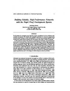
The appearance of buildings in multi-aspect high-resolution SAR images is discussed using a data set covering a part of the city Dorsten in Germany (Fig. 1).
Keywords: multi-aspect, high-resolution, InSAR, building reconstruction, data fusion
I.
INTRODUCTION
The physical principle of SAR sensors is responsible for specific phenomena [1] like foreshortening, layover, shadow and multipath propagation. 3D-building recognition from SAR and InSAR data has been studied for city cores with high buildings [2], rural areas [3] and industrial plants [4], [5]. In the investigated data set occlusions caused by neighboring buildings and groves interfere the data and hamper the analysis [7]. If context knowledge derived from the typical appearance of buildings in SAR data is utilized by a model-based reconstruction approach, then building recognition can be relieved. The proposed building recognition is based on frequently observable lines of bright scattering resulting from
Figure 1. Multi-aspect-InSAR magnitude images
The recording of the InSAR data was taken from a single pass interferometric antenna configuration. Both antennas alternatively illuminate the scene and receive the backscattered complex signals (ping-pong mode). The InSAR-SLC data from Intermap Technologies [6] have a spatial resolution in slant geometry of about 38 cm in range and 16 cm in azimuth direction (X-band). The set of images was taken at two times from two flight directions spanning an angle of about 90°, so that from each direction two image pairs were recorded. The overlapping area (Fig. 1) covers five square kilometers of an urban area with high building density. Interesting are the mixture of industrial and residential areas, which are
characterized by regular groups of buildings with a common alignment in north-south direction and parallel to roads. III.
APPEARANCE OF BUILDINGS IN MULTI-ASPECT SAR IMAGES
In the following typical SAR illumination effects at flat roofed buildings in the case of orthogonal viewing directions are discussed. As example two buildings from the Dorsten urban area (Fig. 2 left) are considered. In Fig. 2 right the physical dimensions of such a building block are shown. 12m
13m 36m
Figure 2. Typical flat roofed building example from Dorsten
The two orthogonal flight directions were approximately from west to east (direction 1) and north to south (direction 2). Corresponding simulations of the specific SAR effects have been accomplished for one building block to compare these simulated effects with those in the measured data. Different effects are depicted in measured (Fig. 3 left) and simulated (Fig. 3 right) magnitude images for both illumination directions.
direction 1
direction 2
measured
simulation
building site faces towards the sensor. Otherwise the roof is mapped very small and only the layover area is visible. A short line of bright scattering for direction 1 and a long one for direction 2 are observable in Fig. 3 left. IV.
APPROACH FOR BUILDING DETECTION AND RECONSTRUCTION
A. Algorithm overview The processing chain starts with the formation of interferometric heights and magnitude images using the complex data of both antennas. It comprises subpixel registration, followed by the interferogram generation. A phase correction is performed to reduce phase ambiguities at building locations. The magnitude images of one aspect are pre-processed and fused. The fusion is performed in slant range applying a maximum operator. In the following segmentation step, lines of bright scattering are extracted from the fused magnitude image. These lines are attributed by their height; lines with attribute ‘high’ and ‘low’ are then distinguishable. Only lines with attribute ‘low’ are projected into a common world coordinate system. This is done individually for both flight directions. Then the lines are merged and L-structures are assembled. The focusing on L-structures benefits from the knowledge of orthogonal flight directions and the assumption of rectangular building footprints. Afterwards building hypotheses are assembled. The resulting building candidates are filtered based on the interferometric heights. Finally rectangles are generated. B. Segmentation of primitive objects in the magnitude images Lines of bright scattering are extracted in the max-fused magnitude image using the Steger-operator [8] and a subsequent linear approximation and prolongation step. To discriminate scatterlines caused by a dihedral corner reflector between ground and building wall from other lines of bright scattering, the interferometric heights in the surrounding area of the lines are considered. Only the lines with a height comparable with the mean height of the area are taken into account in the next processing steps. In Fig. 4 the output of Steger-operator and the prolongation step are overlaid with the max-fused magnitude images.
Figure 3. Flat roofed building measured (left) and simulated (right) magnitude images
The layover phenomenon occurs at locations with steep elevation gradient facing towards the sensor such as at vertical building walls. Layover appears as bright area in the SAR images. Perpendicular alignment of buildings to the sensor leads to strong signal responses by double-bounce scattering at the dihedral corner reflector between ground and building wall. This results in a line of bright scattering in azimuth direction at the building footprint. At the opposite building side the ground is partly occluded by building shadow, which appears as a dark region. Due to the dimensions and the orientation of the buildings relative to the flight direction, the flat roof only results in a visible area in the SAR-image when the small
direction 1
direction 2
steger
prolongation
Figure 4. Line detection (left) and prolongation (right) results
On top of Fig. 4 results for flight direction 1 are shown, on bottom results for flight direction 2. In each case Steger-output on the left side and prolongation output on the right side of the figure. Most of the detected lines are corresponding to real building corners. C. Fusion of primitve objects The resulting primitive objects (lines) are projected into a common world coordinate system individually for both flight directions. This orthorectification is performed with a height individually derived from the calculated InSAR heights for every line.
direction 1
direction 2
Figure 5. Extract of orthorectified lines overlaid with LIDAR
In Fig. 5 the projected lines are overlaid with a LIDARDSM to visualize and interpret the result. Almost all lines derived from direction 2 coincide with the expected building corners. The result based on direction 1 includes some lines not corresponding with buildings and with some distance to the building footprint. This can be ascribed to the appearance of corner reflectors in the magnitude images (Fig. 3 left). In the magnitude subimage of direction 2 corner lines are clearly observable and detectable. In comparison to this the expected corner of the same building appears in the subimage of direction 1 as a blurred broad part of bright scattering. Therefore the fitting of a line in this area can be inaccurate. Because of the fact that the surrounding of the detected line gives the estimated height for the orthorectification, the above mentioned distance to the building footprint in ground range can appear (Fig. 5 left). In Fig. 6 the projected lines from both directions are merged and overlaid with the LIDAR-DSM. Lines derived from direction 1 are drawn in yellow, from direction 2 in red.
D. Detection of L-structures and reconstruction of building candidates Candidate lines for L-structures must hold an angle tolerance (based on the assumption of rectangular building footprints) and a distance threshold. In Fig. 7 derived Lstructures are overlaid again with the LIDAR-DSM.
Figure 7. Derived L-structures overlaid with LIDAR
In Fig. 8 possible line constellations after L-structure calculation are drawn (solid lines). On the left side, the intersection point P of the involved lines is calculated by extrapolating both lines. Only one building candidate exists. In the middle two polygons are extracted (I-II). On the right side, intersection point P of the involved lines is explicitly given by the crossing of both lines. This results in four potential building candidates (I-IV).
Figure 8. Modells of L-constellations
In Fig. 9 all candidate polygons derived from L-structures are depicted. These building candidates are evaluated in a subsequent step. In the case of multiple building candidates for two lines, the polygon covering the maximum area is chosen as resultant candidate (e.g. in Fig. 8 polygon no. I).
Figure 9. Candidate polygons overlaid with LIDAR
Figure 6. Orthorectified lines overlaid with LIDAR
Additionally the covered area has to be at least 80% of the whole spanned area. The mean height, derived from the InSAR-DSM, within the polygon has to be some meters above
mean ground height and the standard deviation of this derived height has to be lower than a threshold. An additional filter criterion exploits the knowledge of orthogonal flight directions. The expected corners form Lstructures depending on the illumination directions. Possible Lstructures are depicted in Fig. 10. The blue colored corners result from direction 1 and the red ones from direction 2. The yellow marked parts contain the allowable variation of orientation for this investigated data set. The left part (v1) shows the acceptable maximum variation for these two flight directions and the right part (v2) the expected most reliable one.
building hypotheses were excluded. Furthermore also some obviously right detected buildings were removed, so that an improvement of the assessment process is a starting point for further investigations. In Fig. 12 the resultant building footprints for an extract of the investigated scene are shown. On the left side, the result is overlaid with the LIDAR, on the right side with an orthophoto of the same area. Noticeable results are buildings detected in the InSAR data and not visible in the LIDAR data but confirmed by the orthophoto. This fact should be considered if the LIDAR data is used as ground truth.
Figure 12. Extract of result overlaid with LIDAR (left) and VIS (right)
Figure 10. Orientations of L-structures
If the remaining polygons overlap with other hypotheses (polygons) then the most likely one is derived based on calculated polygon features (standard deviation and mean of height). In Fig. 11 the results for different orientation variation (left v1, right v2) are shown.
In future work a combination of the proposed approach and the approach in [7] should be investigated. Also the calculation of the InSAR heights should be improved to reach a quality that allows operations like erosion to derive the building footprint from the polygon candidate. Deviations between simulations, based on the extracted buildings, and the real data will be considered in further investigations. REFERENCES [1]
[2] Figure 11. Building candidates for different orientation variation
In each case the building candidate polygon is drawn in red and the corresponding rectangular building footprint is derived by a minimum bounding rectangle of the polygon drawn in yellow. V.
RESULTS AND CONCLUSIONS
The final building reconstruction results are shown in Fig. 11. Partially the derived building footprint coincides very well with the ground truth especially when the assumptions about form and dimensions are correct. Sometimes the derived scatterlines are extended because of adjacent trees. More complex structures are not detectable with this approach. E.g. in the upper right corner of Fig. 11 right only a surrounding rectangle for a building with U-shape is found.
[3]
[4]
[5]
[6]
[7]
[8]
The limitation of the orientation illustrated in Fig. 10 reduced the full group of building candidates (Fig. 9) in an expedient way. The expected improvement of the results by the orientation assumption v2 was not achieved. Only some false
G. Schreier,"Geometrical Properties of SAR Images," G. Schreier (ed, SAR Geocoding: Data and Systems, Karlsruhe, Wichmann, 1993, pp. 103-134 P. Gamba, B. Houshmand, M. Saccini, "Detection and extraction of buildings from interferometric SAR data," IEEE Transactions on Geoscience and Remote Sensing, Vol. 38, No.1, 2000, pp. 611-618 R. Bolter, "Buildings from SAR: Detection and Reconstruction of Buildings from Multiple View High Resolution Interferometric SAR Data," University Graz, Phd. Thesis, 2001 U. Soergel, K. Schulz, U. Thoennessen, "Phenomenology-based segmentation of InSAR data for building detection," B. Radig, S. Florczyk (eds), Pattern Recognition, 23rd DAGM Symposium, Springer, 2001, pp. 345-352 E. Simonetto, H. Oriot, R.Garello, “Rectangular building extraction from stereoscopic airborne radar images,” IEEE Transactions on Geoscience and Remote Sensing, Vol. 43, No.10, 2005, pp. 2386-2395 M. Schwaebisch, J. Moreira, "The high resolution airborne interferometric SAR AeS-1," Proceedings of the Fourth International Air-borne Remote Sensing Conference and Exhibition, Ottawa, Canada, 1999, pp. 540-547 A. Thiele, U. Thoennessen, E. Cadario, K. Schulz, “Building recognition in urban areas from multi-aspect high resolution interferometric SAR data,” to be published C. Steger, "An unbiased detector of curvilinear structures," IEEE Transactions on Pattern Analysis and Machine Intelligence. Vol. 20, No. 2, 1986, pp. 113-125.