Cached-Code Compression for Energy Minimization in Embedded Processors Luca Benini Universita di Bologna Bologna, ITALY 40136
Alberto Macii Politecnico di Torino Torino, ITALY 10129
Alberto Nannarelli, Universiti di Roma Tor Vergata Roma, ITALY 00133
[email protected]
[email protected]
[email protected]
ABSTRACT
Numerous code compression techniques have been proposed for reducing instruction memory size in low-cost embedded applications [l].The basic idea is to store programs in compressed form and decompress them on-the-fly at execution time. Later, researchers have realized that code compression can be beneficial for energy as well, because it reduces the energy consumed in reading instructions from memory and communicating them to the processor core [2, 3, 41. Code compression leverages well-known lossless data compression techniques, but it is characterized by two constraints. First, it must be possible t o decompress a program in relatively small blocks, as instructions are fetched, and starting from several points inside the program (i.e., branch destinations). Hence, techniques that decompress a stream starting from a single initial point are not applicable without changes. Second, the decompressor should be small, fast and energy efficient, because its hardware cost must be fully amortized by the corresponding savings in memory size and energy, without compromising performance. For simple processors with no instruction cache, the decompressor is either merged with the processor core itself, or placed between program memory and processor. The first solution has been implemented in several commercial core processors, in form of a “dense” instruction set, with short instructions (e.g., ARM Thumb and MIPS16 instruction sets). The second solution has been investigated in several papers [2, 5 , 6, 31. Supporting restricted instruction sets requires changes to the core architecture, while an external decompressor does not. Furthermore, with an external decompressor it is possible to aggressively tailor code compression to a specific embedded application. Hence, external decompression is well-suited for embedded designs employing third-party cores, which are the focus of this paper. In more advanced architectures containing an instruction cache, the decompressor can be placed either between the I-cache and the main memory (decompress on cache refill, or DCR architecture), or it can be placed between the processor and the I-cache (decompress on fetch, or DF architecture). Both alternatives have been investigated in the recent literature [4, 71. In [4], it was shown that from an energy and performance viewpoint, the DF architecture is superior to the DCR architecture, when decompressor overhead is small. The main reason for this effect is that instructions are stored in cache in a compressed fashion, effectively increasing cache capacity. However, current silicon implementations of code compression are based on the DCR architecture, indicating that reducing decoding overhead is a non-trivial task that still entails significant challenges.
This paper contributes a novel approach for reducing static code size and instruction fetch energy for cache-based core processors running embedded applications. Our irnplementation of the decompression unit guarantees fast and lowenergy, on-the-fly instruction decompression a t each cache lookup. The decompressor is placed outside the core boundaries; therefore, processor architecture does not need any modification, making the proposed compression approach suitable to IP-based designs. Viability of our solution is assessed through extensive benchmarking performed on a number of typical embedded programs.
1. INTRODUCTION Embedded processors are often the main computational engines for modern system-on-chip (SoC) architectures. Processors for embedded applications have traditionally been extremely simple (8-bit or 16-bit CPUs), because of tight cost constraints coupled with loose performance demand. The increasing level of integration and computational speed requirements, fueled by the new generation of embedded computing tasks (e.g., DSP, high-bandwidth data transfer, etc.) have changed the picture. Currently, many embedded processors are based on high-performance RISC architectures, with on-chip cache and full support for complex memory systems and peripheral controllers. Such processors, and their software development environments, are usually purchased by system integrators from third-party companies that specialize in embedded core design. One of the key challenges in designing a complex system around a high-performance embedded RISC processor is to ensure sufficient instruction fetch bandwidth to keep the execution pipeline busy. The regularity of RISC instruction sets eases application and compiler development, but hinders code compaction. For this reason, designers and researchers have put significant effort in devising techniques for improving code density and reducing instruction-related costs, in terms of speed, area and energy. Permission to make digital or hard copies of all or part of this work for personal or classroom use is granted without fee provided that copies are not made or distributed for profit or commercial advantage and that copies bear this notice and the full citation on the first page. To copy otherwise, to republish, to post on servers or to redistribute to lists, requires prior specific permission and/or a fee. ISLPED’Ol, August 6-7, 2001, Huntington Beach, California, USA. Copyright 2001 ACM 1-58113-371-5/01/0008...$5.00.
322
The main issue with the D F approach is that decompression is performed on every instruction fetch. In other words, the decompressor is on the critical path for the execution of every instruction, not only for cache refills. If its delay is not small, it may significantly slow down execution. Furthermore, it consumes energy on every instruction fetch, while in the DCR architecture it can be activated only on cache refills. Careful implementation of the decompression unit is thus key for making D F applicable in practice. This paper proposes a novel D F architecture that focuses on reducing decoding overhead on energy and performance. First, our technique guarantees that storage requirements for the compressed program always decrease. Second, the compression algorithm has been designed specifically for fast and low-energy decoding during cache lookup. Compressed instructions are always aligned to cache line boundaries, branch destinations are word-aligned and instruction decompression is based on a single lookup into a small (and fast) memory buffer. Third, we do not limit our analysis to the architecture level, but present a complete implementation of the cache-decompressor block, including detailed analysis of its energy and delay. We have benchmarked the proposed compression technique on a number of programs implementing functions typical of embedded computations. The achieved code size reductions, averaged over all the experiments, are around 28%. From the energy point of view the improvements vary a lot depending on cache size, original and compressed code size, dynamic memory access profile, and kind of adopted program memory (i.e., on-chip vs. off-chip). For example, for a 4Kbyte cache and an on-chip program memory, average energy savings are around 30%. This value grows to 50% for a system with a cache of the same size but an off-chip program memory. Cache performance are also very sensitive to cache and code size. For a 4Kbyte cache, the average hit ratio improves by 19%.
are compressed using arithmetic coding. For branches, only destination displacement is variable-length coded. Fast dictionary instructions, with no immediate are compressed to a one-byte code and decompressed using a 256-entries lookup memory. Uncompressed instructions are left intact, and extended with a 3-bit preamble. Even though Lekatsas reports on decoding energy consumption, no information is provided in [4] on decoder area, speed and its interaction with cache (for instance, cache line unpacking, and branch destination re-mapping in the case of non word-aligned branch destinations, are not described). Furthermore, appending a 3-bit preamble to uncompressed instructions may cause run-time decompression inefficiency, if many uncompressed instructions are fetched during program execution.
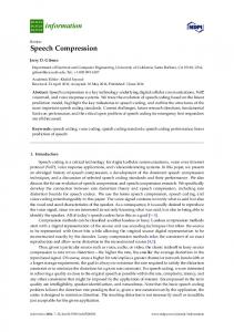
2.2 A Low-Overhead DF Architecture The compression algorithm described in the sequel is tailored for efficient hardware implementation. The decompressor is merged with the cache controller, and instructions are decompressed on the fly as they are extracted from the cache. Instructions are compressed in groups with the size of one cache line. In describing the algorithm, we will assume a direct-mapped cache with 4-word lines (L = 128 bits) and one-word (W = 32 bits) uncompressed instructions. However, our approach can be extended to caches with any associativity and line size. We will use the DLX as target core processor, because it has a simple 32-bit RISC architecture with several open-source synthesizable implementations, and an open-source, widely known software development environment. Moreover, the DLX is similar to several commercial RISC processors, such as the simplest cores in the ARM and MIPS families. Compression is targeted to a specific program thanks to execution profiling. The code is initially profiled and the subset SN of the N most frequently executed instructions is obtained. Without loss of generality, we assume in the following N = 256. Similarly to [3] and [4] (fast dictionary instruction), ZogzN-long compressed codes (8 bits, in our case) axe assigned to the N most frequent instructions. However, the decision of compressing an instruction i , even if it belongs to set S,+,r depends o n the neighboring instructions that would fit in the same cache line. More specifically, instruction i is compressed only if it belongs to a group of instructions that can be stored in a compressed line. The latter is a group of more than four adjacent instructions which, after compression, will be stored in four consecutive words. The size (four words) and the memory alignment of a compressed line is such that it fits in a single cache line, when it is cached. The detailed structure of a compressed line is shown in Figure 1.
2. DECOMPRESSION ON FETCH 2.1 Previous Work We begin this section by outlining the characteristics of two previously published D F approaches, by Larin et al. [7], and by Lekatsas et al. [4]. Larin’s approach targets VLIW processors and compresses instructions using the Huffman algorithm. Basic blocks of compressed instructions are transferred and stored into the I-cache atomically. Compressed instructions are not aligned to cache line boundaries. On a cache access, two consecutive cache lines are decompressed and stored in a level-zero buffer. The following instructions are fetched in sequence from the buffer, until it is emptied, or a branch is executed. The paper by Larin does not report any data on energy, speed or area of the decoder, but its high hardware cost is apparent. Fetching and decoding two cache lines at a time imposes parallel Huffman decoding of multiple instructions in one clock cycle (even single-instruction Huffman decoding requires a quite large hardware block). Furthermore, branch targets addresses in compressed code are stored in a dedicated address re-mapping memory that must be accessed on every taken branch. Lekatsas approach clusters instructions in four groups (instructions with immediates, branches, fast dictionary instructions and uncompressed instructions) identified for decoding purpose by a unique prefix. Instructions with immediate
Figure 1: Compressed Line Structure. MARK 12 2bil flags
1 1 1 1 1
The first word of the line contains a mark and a set of flag bits. The mark is an unused instruction opcode (in DLX, we have 6-bit opcodes), while the flag bits are divided in 12 groups of 2 bits each, one group for each of the bytes of the remaining three words of the line. One additional flag bit L is reserved at the end of the flags.
323
line, but it cannot, because after two consecutive UIs, compression would be convenient only if we had at least three consecutive CIS, but we have only two. Hence, the UI-D and the following three instructions are stored uncompressed in memory. Notice that this choice implies that two CIS are not compressed. I n compressed memory, this case is marked as (U)CI. A similar decision is taken for the next four instructions, which are, again, stored i n uncompressed form. Finally, the last 7 instructions are stored i n a compressed line. Notice that: (i) The compressed line contains an uncompressed instruction; (ai) The first empty byte is due to the branch alignment constraint (branch destinations must be word-aligned). Flags f o r the second compressed line are: ~~.OO.~O.O~.Ol.O1.O~,ll.OO.OO.iO.ll.l. For this example, compression reduced code size f r o m 24 words to 16.
The flags values are assigned as follows: 00 if the corresponding byte contains a compressed instruction; 01 if the corresponding byte contains 8 bits of an uncompressed instruction (a compressed line may contain an uncompressed instruction); 11 if the corresponding byte is left empty for alignment reasons (see below). Flag value 10 is used to signal the last compressed instruction in the line, in case of lines containing compressed instructions. Finally, the last flag bit L marks if the last instruction in the line is compressed (bit set to 0) or not (bit set to 1). By construction, a compressed line stores between a minimum of 5 instructions, and a maximum of 12 instructions. Thus, the best compression achievable is a factor of 4. The compression algorithm analyzes the code sequentially, starting from the first instruction (assuming that it is aligned to cache line boundary), and tries to pack adjacent instructions in compressed lines. If the compressed line contains more than 4 words, all instructions belonging to SN.are compressed to their log2N codes, the mark and flags are inserted in the first word of the compressed line and empty bytes are inserted when required for alignment reasons. Otherwise, instructions are not compressed even if they belong to SN. The compression procedure guarantees that compressed code is never larger than the original code. Furthermore, the number of bits transferred from memory to cache when executing compressed code is never larger than for the uncompressed case. To facilitate an efficient hardware implementation of the decoder, we guarantee two types of alignment: 0
0
Figure 2: Code Compression Example. Originalmemory
Compressed memory
No instruction is allowed to go across a cache line boundary. This rule ensures that only a single cache line needs to be accessed a t every instruction fetch, thus avoiding expensive double-line accesses, which require dual-bank caches [7]. Instructions at branch destinations are always wordaligned. This rule allows us to eliminate the address translation table, since branch addresses in original code can be replaced with legal, word-aligned branch destination addresses in the compressed code.
During program execution, on every cache miss, a new cache line is fetched from memory. The line may either contain four uncompressed instruction, or a first word containing mark and flags, followed by three words containing five or more compressed instructions. The cache controller examines the first word of the line. If a mark is detected, it proceeds to fetch instructions according to the indications provided by the flag bits. Decompression is performed by addressing the decompression table (a fast RAM containing 256 32-bit words) with the 8-bit compressed instruction code. A detailed description of the hardware decompression engine is provided in the next section. More information on the implementation of the compression algorithm and the related profiling and instruction selection flow is provided in Section 4.
Alignment constraints imply some losses in code density, because a few bytes in compressed lines may be left empty. However, this effect is taken into account when deciding whether a group of instructions can be compressed or not.
EXAMPLE 1. Figure 2 shows code compression at work. I n the original memory map, instructions are marked with CI if they belong to SM (i.e., candidate f o r compression), with U1 if they do not. Tag -D- is placed on instructions which are at a branch target. The arrows on the left of the memory maps represent cache line alignment (i.e., the words between two arrows are cached on the same cache line). The compression algorithm moves f r o m the top of the original memory map, and tries to pack as many instructions as possible in a compressed line. The first group of 9 CI instructions fits, after compression, into a compressed line. The following instruction is a U1 (and a branch destination), which does not fit in the remaining two bytes of the compressed line. Hence, the last three bytes are left empty. The flags for the first compressed line are: 00.00.00.00.00.00.00.00.10.~~. 11.11.1. The adgorithm then tries to fit the following instructions into a compressed
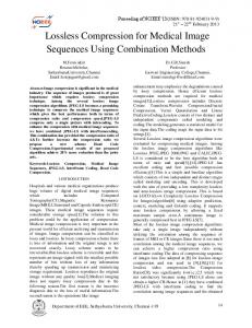
3. DECOMPRESSION HARDWARE The hardware which performs the on-the-fly decompression is embedded in the cache controller. The cache controller is divided into a number of units: A master controller, called “main controller” in the sequel, which handles the communication with the CPU, a slave controller, called “miss handler” in what follows, which supervises the transfers from main memory to the cache when a read miss occurs, and a program counter update unit (PC-unit). 324
The decompression-cache system, sketched in Figure 3, is completed by the following units: The cache array of 256 x 4 words, plus tags of 20 bits. A MUX placed at the output of the cache array. A memory holding the compressed instructions (IDT). A MUX between the cache and the data bus, driven by the main controller, which selects either the output of the cache array (for uncompressed instructions) or the output of the IDT (for compressed instructions).
The CPU does not know if the instruction under execution is compressed or not. Therefore, the Program Counter (PC) is incremented by 4 for each instruction, assuming sequential code. However, compressed instructions in the cache occupy 1 byte instead of 4, and this causes a problem of misalignment between the PC and the actual address of the instruction to fetch, or in other words, the program counter tends to ”run f o r w a r d ” . To solve this problem, which affects relative jumps, we can opt for two solutions:
Figure 3: Decompression Unit.
0
0
DATA BUS
C P U
5
Id e
ADDRESS BUS
If the CPU core is modifiable, we can stop the P C increment when reading inside the same cache word multiple compressed instructions. This can be accomplished with modest hardware additions. If the CPU core is sealed-off, we have to replicate the P C logic inside the decompressor-cache. Realignment of CPU P C and cache P C is done when a jump to a register is executed ( ” j r register” in the DLX instruction set).
The second solution is obviously more expensive in terms of hardware requirements: A 32 bit adder plus two 32 bit registers (one to hold the PC, one to hold the possible target of a jump) have to be placed in the decompressor (PC-unit). Moreover, an additional problem arises in case of subroutine calls. The DLX instruction ’3al address” performs two tasks upon execution:
Fetch req
When a memory read access is issued by the CPU, the address (index) is passed to the cache and, when the datum is ready, the main controller performs tag checking. On a tag mismatch (i.e., a miss), the main controller enables the miss handler, puts its command and address buses toward the cache in high-impedance and sets itself in idle state. On a read miss, the miss handler is woken up by the main controller and the requested block (4 words) is transfered to the cache. Upon completion, the miss handler signals to the main controller the end of the transfer, puts its command and address buses toward the cache in high-impedance and sets itself in idle state. In case of a cache hit, the main controller executes the following tasks:
1. The PC (return address) is stored in register 31 2. The CPU jumps to ”address”. To get the correct return address from the subroutine, we store in register 31 the cache PC instead of the CPU PC. This is done by changing instruction ”jal address” (during compression) with two instructions: ”1w r31, (don’t care)” ” j address”
and by sending the value of the cache P C on the data bus at the right time. In this way, when the subroutine ends (instruction ’3r $31 ”), the correct address of the compressed program is restored and the CPU PC is realigned. The decompressor introduces an overhead on the timinig as well. In normal cache operation, the time required to fetch the instruction, in case of hit, is:
1. It reads the first word of the block (or cache line) to check if such block contains at least a compressed instruction. This is done by matching the first 6 bits (opcode) with the pattern indicating a compressed line. 2. According to the result of the matching, it selects the appropriate instruction by setting the control lines of cache and data bus MUXes.
t fetch--wo = t c a c h e
+ tmatch f t b u s E N
where t c a c h e is the time necessary to access the cache and transfer the data through the cache MUX, tm&h is the time needed for tag-matching, and t b u s E N is the time to enable the tristate buffer if a hit occurred. In the decompressor, the time required to fetch a compressed instruction (worst case) is:
If the cache line contains at least one compressed instruction, the main controller performs some additional work: i ) It stores the flag bits of the mark in a mask register on the first visit to the cache line. ai) It checks the flag bits corresponding to the requested instruction. If it is compressed, the main controller issues the IDT address to be accessed; otherwise, it selects the appropriate word by operating the cache MUX. Finally, it executes task 2 above. To keep track of the instruction to be fetched, in case of compression, the main controller updates a 4-bit counter. Every time a new cache line is requested or the current instruction is the target of a branch, the main controller resets the counter to the appropriate value, and then it increments it by 1, if the current instruction is compressed, or by 4, if the current instruction is not compressed.
tfetch-dec
= tcache
+ t g e n + t I D T + tmz122:l + t b v s I N
where tgenis the time for IDT address generation, t I D T is the IDT access time, t m u z 2 : 1 is the in-to-out delay of the 2:l MUX, and tbus1.N is the transfer time through the tristate buffer. We used a 0.25pm, 2.5V library of standard cells from ST to implement our decompressor and found the values for the timing and energy per cycle reported in Tables 1 and 2. Synthesis was performed using Synopsys Design Compiler, and energy estimation using Synopsys Power Compiler. 325
Delay
W/O Dec.
b l tcache
2.2
tmatch
0.6
The results of Tables 3 and 4 refer to a system with a 4Kbyte cache. In Tables 5 and 6 we explore how cache performance and energy consumption change a:; the cache size changes (we consider the case of 8Kbyte and 2Kbyte caches). We observe some contradictory effects that yield results which are not always intuitive. For example, a larger cache increases the hit ratio, thus limiting the number of times the background memory is accessed also for the case of uncompressed programs. This causes a substantial decrease in bus and memory energy for both uncompressed and compressed execution. In addition, cache access cost is higher and the decompression overhead is no longer compensated due to the lower absolute contribution of bus and main memory to total energy. As a consequence, the usefulness of compressing the code decreases; average energy savings are, in fact, around 8%, and there are programs for which energy even increases. For a smaller cache, the hit ratio tends to decrease. This causes a strong increase in bus and memory energy, especially for the uncompressed code. In addition, cache access cost decreases. As a result, energy reductions are more sizable. We can then conclude that the relationship between energy, compression ratio and cache hit ratio is very complex; as such, intensive and exhaustive code profiling and dynamic simulation are the basic ingredients for achieving a satisfactory trade-off. We close with some results for the case where accesses to memory go off chip. The memory is a 4Mbit FLASH at 2.5V from ST; the energy cost for accessing a 4-word location is 21.4 nJ. The bus load we have assumed is 8pF per line. Tables 7 and 8 show data similar to those in Tables 3 and 4. Although compression ratios and hit ratios remained unchanged, larger energy savings are observed (i.e., the average is around 50%) due to the much more penalizing effect introduced by off-chip bus and memory accesses.
With Dec. [nsl 2.2
Table 2: Energy per Cycle of Blocks in Figure 3. Block Miss Handler 4.2e-11 Cache Mux Sparse Logic IDT (256 x 32) Cache
4.
3.2e-9
7.0e-10 3.2e-9
EXPERIMENTAL RESULTS
In this section, we report data on the use of the proposed compression scheme. Software programs we considered for the experiments are some of the C benchmarks distributed in the Ptolemy [8] package; they implement functions that are widely exploited in embedded systems for DSP. Data collection has been done using the SuperDLX [9] compilation and simulation environment. We have used, as program memory, a 512Kbyte SRAM from ST, organized in eight banks of 32K x 16 and built in 0.25pm technology at 2.5V. The energy access cost, in read mode, is 17.2 nJ per memory block of four, 32-bit words. The line capacitance we used for determining the address and data bus energy is 0.6pF. Table 3 summarizes all the results for the case of a 4Kbyte cache. In particular, for each benchmark progra,m and for both original and compressed execution, it reports static code size (column Size), cache hit ratio (column HR) and total energy consumption (column Energy). The total number of executed instructions is provided on the left of the table (column Exec. Innstr.), while the percentage of variation introduced by the compression on code size, hit ratio and energy is summarized in column A. Average code size reduction is around 28%, with a peak value around 61% for program chaos. Cache performance improve, on average, by 19%, with a maximum increase in the hit ratio of 34% for benchmark integrator. Finally, energy decreases, on average, by 30%, with peak reductions for programs chaos and interp around 48% and 53%, respectively. Energy figures are further detailed in Table 4, where a breakdown of all the contributors to the total values (i.e., cache including the decompressor, address and data buses, background memory) is shown. Clearly, the energy consumed in the cache system increases substantially w.r.t. the case of uncompressed code, since it includes the energy for instruction decompression which is required for ea.ch fetched instruction (coming from both cache and memory). Obviously, decrease in bus and memory energy well compensates the overhead of the decompressor.
5. CONCLUSIONS We have proposed a new approach for reducing static code size and instruction fetch energy for embedded processors with cache. The method pairs efficiency in the compression with a low-overhead implementation of the decompressor. Experiments on several benchmarks have shown average code compression results around 28% and average energy savings of about 30%.
6. REFERENCES [ l ] C. Lefurgy, Eficzent Executzon of Compressed Programs, Doctoral Dissertation, University of Michigan, 2000. [2] Y. Yoshida, B.-Y. Song, H. Okuhata, T. Onoye, I. Shirakawa, “An Object Code Compression Approach t o Embedded Processors,” ISLPED-97, pp. 265-268, 1997. [ 3 ] L. Benini, A. Macii, E. Macii, M. Poncino, “Selective Instruction Compression for Memory Energy Reduction in Embedded Systems,” ISLPED-99, pp. 206-211, 1999. [4] H. Lekatsas, 3 . Henkel, W. Wolf, “Code Compressicm for Low Power Embedded Systems Design,” DAG-00, pp. 294-299, 2000. [5] S. Y. Liao, S. Devadas, K. Keutzer, “Code Density Optimization for Embedded DSP Processors Using Data Compression Techniques,” IEEE Trans. on C A D , Vol. 17, No. 7, pp. 601-608, 1998. [6] H. Lekatsas, W. Wolf, “Code Compression for Embedded Systems,” DAC-00, pp. 516-521, 1998. [7] S. Larin, T. Conte, “Compiler-Driven Cached Code Compression Schemes for Embedded ILP Processor:;,” MICRO-32, 1999. [ 8 ] J. Davis I1 et al., Overvzew of the Ptolemy Project, UCB/ERL Tech. Report No. M99/37, UC Berkeley, 1999. [9] C. Moura, SuperDLX: A Generzc Superscalar Szmulator, ACAPS Technical Memo 64, McGill Univ., 1993.
326
Bench
Bench
ETCC.I n d t r . [#I
W d h o u f Compwrrion Size HR Enevgv [%I [Jl
Enet,!gg Without C o m p r e s a m n [J] C~ichc I BUB I SRAM
11 11
E z e e . Insti-. [#I
II
W d h C"mp?.ell'o,, S~za
[Kbytel
HR
[%I
11
[Jl
11
11
Cache
With Conzyrraaron HR En e q y [%I [Jl
Sire
HR
Ene,g!,
SlZC
[Kbytel
[%I
[Jl
[KbyteI
A HR
S~rs [%I
Enevgy
Encvqy With Compveaa~on[ J ] Coehe I Btu SRAM
W L t h O l L t Comp7.esJLon
Bench
11
[Kbytel
I
[%I
[%I
A Diu
II
I
Ene~gy
[%I
RAM S
A
S~zr I%]
HR
E nelg!,
[%I
[%I
Table 6: Compression Results: 2Kbyte Cache and On-Chip SRAM.
Bench
Ezec. In.*+.
[#I
W d h o s t Compverrion Size HR Eneqy [Kbytel [%I [Jl
I
I
Wlth Size [Kbytel
C"l"p"sS'orL
HR
[%I
Emqy
[Jl
II
A
Site
HR
[%I
[%I
Enevyy [%I
Table 8 : Energy Break-Down: System with 4Kbyte Cache and Off-Chip FLASH.
327