Calculating the reflectance map. Berthold ... map, R(p,q), gives scene radiance as a function of sur- .... tegral of radiant intensity over the full sphere of possible.
Calculating the reflectance map Berthold K. P. Horn and Robert W. Sjoberg
It appears that the development of machine vision may benefit from a detailed understanding of the imaging process. The reflectance map, showing scene radiance as a function of surface gradient, has proved to be helpful in this endeavor. The reflectance map depends both on the nature of the surface layers of the objects being imaged and the distribution of light sources. Recently, a unified approach to the specification of surface reflectance in terms of both incident and reflected beam geometry has been proposed. The reflecting properties of a surface are specified in terms of the bidirectional reflectance-distribution function (BRDF). Here we derive the reflectance map in terms of the BRDF and the distribution of source radiance. A number of special cases of practical importance are developed in detail. The significance of this approach to the understanding of image formation is briefly indicated.
I. Reflectance Map The apparent brightness of a surface patch depends on the orientation of the patch relative to the viewer and the light sources. Different surface elements of a nonplanar object will reflect different amounts of light toward an observer as a consequence of their differing attitude in space. A smooth opaque object will thus give rise to a shaded image, in which brightness varies spatially, even though the object may be illuminated evenly and covered by a uniform surface layer. This shading provides important information about the object's shape and has been exploited in machine vision.1-8 A convenient representation for the relevant information is the "reflectance map".4'6 The reflectance map, R(p,q), gives scene radiance as a function of surface gradient (p,q) in a viewer-centered coordinate system. If z is the elevation of the surface above a reference plane lying perpendicular to the optical axis of the imaging system, and i f x and y are distances in this plane measured parallel to orthogonal coordinate axes in the image, p and q are the first partial derivatives of z with respect to x and y: p = Qz/Qx and q = Qz/Qy. The reflectance map is usually depicted as a series of contours of constant scene radiance (Fig. 1). It can be measured directly using a goniometer-mounted sample, or indirectly from the image of an object of known shape. Alternatively, a reflectance map may be cal-
The authors are with MIT Artificial Intelligence Laboratory, Cambridge, Massachusetts 02139. Received 27 January 1979. 0003-6935/79/111770-10$00.60/0. © 1979 Optical Society of America. 1770
APPLIED OPTICS / Vol. 18, No. 11 / 1 June 1979
culated if properties of the surface material and the distribution of light sources are given. One purpose of this paper is to provide a systematic approach to this latter endeavor. Another is to derive the relationship between scene radiance and image irradiance in an imaging system. This is relevant to machine vision since gray levels are quantized measurements of image irradiance. II. Microstructure of Surfaces When a ray of light strikes the surface of an object it may be absorbed, transmitted, or reflected. If the surface is flat and the underlying material homogeneous, the reflected ray will lie in the plane formed by the incident ray and the surface normal and will make an angle with the local normal equal to the angle between the incident ray and the local normal. This is referred to as specular, metallic, or dielectric reflection. Objects with surfaces of this kind form virtual images of surrounding objects. Many surfaces are not perfectly flat on a microscopic scale and thus scatter parallel incident rays into a variety of directions (Fig. 2). If deviations of the local surface normals from the average are small, most of the rays will lie near the direction for ideal specular reflection and contribute to a surface shine or gloss. Other surface layers are not homogeneous on a microscopic scale and thus scatter light rays which penetrate the surface by refraction and reflection at boundaries between regions with differing refractive indices (Fig. 3). Scattered rays may reemerge near the point of entry with a variety of directions and so contribute to diffuse, flat, or matte reflection. Snow and layers of white paint are examples of surfaces with this kind of behavior. Frequently both effects occur in
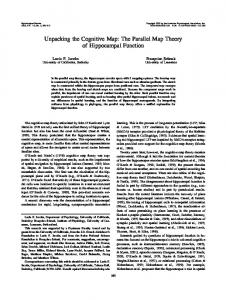
Fig. 1. A typical reflectance map for a surface, with both a glossy and a matte component of reflection, illuminated by a point source. The coordinates are surface slope in the x and y directions, and the curves shown are contours of constant scene radiance. ,
Fig. 2. Undulations in a specularly reflecting surface causing scattering of incident rays into a variety of directions. The surface will not appear specular if it is imaged on a scale whert the surface undulations are not resolved. It may instead have a glossy appearance.
Fig. 3. Inhomogeneities in refractive index of surface layer components cause incident rays to be scattered into a variety of directions upon reflection. This kind of surface microstructure gives rise to matte reflection.
surface layers, with some rays reflected at the nearly flat outer surface of the object, while others penetrate deeper and reemerge after multiple refractions and reflections in the inhomogeneous interior. The distribution of reflected light in each case above depends on the direction of incident rays and the details of the microstructure of the surface layer. Naturally, what constitutes microstructure depends on one's point of view. Surface structures not resolved in a particular imaging situation are taken here to be microstructure. When viewing the moon through a telescope, for example, smaller hillocks and craterlets are part of this microstructure. This consideration leads to more complicated models of interaction of light with surfaces than those discussed so far. It is possible, for instance, to consider an undulating surface covered with a material, which in itself already has complicated reflecting behavior (Fig. 4). Reflectance is not altered by rotating a surface patch about its normal when there is no asymmetry or preferred direction to either the pattern of surface undulations or the distribution of subsurface inhomogeneities. Many surface layers behave this way and permit a certain degree of simplification of the analysis. Exceptions are such things as diffraction gratings, iridescent plumage, and the mineral called tiger eye. These all have a distinct directionality in their surface microstructure and will not be considered here further. Considerable attention has been paid to the reflective properties of various surface layers. Some researchers have concentrated on the experimental determination of surface reflectance properties.9""21 At the .same time, many models have been developed for surface layers based on some of the considerations presented above.22"36 Models often are too simple to be realistic, or too complicated to yield solutions in closed form. In the latter case, Monte Carlo methods can be helpful, although they lead only to numerical specification of the reflecting behavior. Purely phenomenological models of reflectance36have found favor in the computer graphics community. "38 Several books have appeared describing the uses of reflectance measurements in determining basic optical properties of the materials in-
•^y^^^^^-
Fig. 4. Compound surface illustrating more complex model of interaction of light rays with surface microstructure. 1 June 1979 / Vol. 18, No. 11 / APPLIED OPTICS
1771
volved.39"*1 Attention has been paid, too, to the. problem of making precise the definitions of reflectance and related concepts.42'43 III. Radiometry A modem precise nomenclature for radiometric terms has been promoted by a recent NBS publication.43 Table I gives the terms, preferred symbols, and unit dimensions of the radiometric concepts we will have occasion to use for the development presented here. Radiant flux $ is the power propagated as optical electromagnetic radiation and is measured in watts (W). The radiant intensity I of a source is the exitant flux per unit solid angle and is measured in watts per steradian (W-sr~1). The total flux emitted by a source is the integral of radiant intensity over the full sphere of possible directions {4v si). The irradiance E is the incident flux density, while radiant exitance M is the exitant flux density, both measured in watts per square meter of surface (W'm~2). The total radiant exitance equals the total irradiance if the surface reflects all incident light, absorbing and transmitting none. The radiance L is the flux emitted per unit foreshortened surface area per unit solid angle. Radiance is measured in watts per square meter per steradian (W-m"2^"1). It can equivalently be defined as the flux emitted per unit surface area per unit projected solid angle. Radiance is an important concept since the apparent brightness of a surface patch is related to its radiance. Specifically, image irradiance will be shown to be proportional to scene radiance. Radiance is a directional quantity. If the angle between the surface normal and the direction of exitant radiation is 9, the foreshortened area is the actual surface area times the cosine of this angle 9. Similarly the projected solid angle is the actual solid angle times the cosine of the angle 9. Here we will use the symbol w to denote a solid angle, while ft will be used to denote a projected solid angle. If dw and d^l are corresponding infinitesimal solid angles and projected solid angles, respectively, dft = dw-cosO. The following example (Fig. 5) will illustrate some of these ideas. Consider a source of radiation with intensity I in the direction of a surface patch of area dA, oriented with its surface normal making angle 9 with the line connecting the patch to the source. In fact, as seen from the source, it appears only as a patch of area c?Acosf) would when oriented perpendicular to this line. The corresponding solid angle is simply the area of this equivalent patch divided by the square of the distance from the source to the patch. Thus, dw = dA • cos8/r2
The flux intercepted then is d* = I - d u = /• dA • cos9/r2
The irradiance of the surface is just the incident flux divided by the area of the surface patch: E=dWA» I - cos9/r2 1772
APPLIED OPTICS / Vol. 18, No. 11 / 1 June 1979
Table I. Radiometric Concepts Radiant flux Radiant intensity Irradiance Radiant exitance Radiance
1= d9/dw E=• dWA M--' dWA L=• d^WA • coa9 •dw)
W W •sr-i W •m-2 W •m- 2 W • m"2 • sr~1
SURFACE
Fig. 5. Point source illuminating a surface, illustrating basic radiometric concepts.
Fig. 6. Local geometry of incident and reflected rays needed for the definition of the bidirectional reflectance-distribution function (BRDF) (redrawn from Ref. 43). IV.
Bidirectional Reflectance-Distribution Function
The Bidirectional Reflectance-Distribution Function (BRDF) was recently introduced by Nicodemus et al.43 as a unified notation for the specification of reflectance in terms of both incident- and reflected-beam geometry. The BRDF is denoted by the symbol f r and captures the information about how bright a surface will appear, viewed from a given direction, when it is illuminated from another given direction. To be more precise, it is the ratio of reflected radiance dLr in the direction toward the viewer to the irradiance dJS, in the direction toward a portion of the source. In symbols, /,-(Mi;Or.0r) = dLr(Oi, together indicate a direction, the subscript i denoting quantities associated with incident radiant flux, while the subscript r indicates quantities associated with reflected radiant flux.43 The geometry is as depicted in the figure (Fig. 6). A surface-specific coordinate system is erected with one
axis along the local normal to the surface and another defining an arbitrary reference direction in the local tangent plane. Directions are specified by polar angle Q (colatitude) measured from the local normal and azimuth angle 0 (longitude) measured anticlockwise from the reference direction in the surface. In general, incident flux may arrive from many portions of extended sources, so incident radiance L((0,,0;) is a function of direction. If we consider the component of flux d^i arriving on the surface patch of area dA from an infinitesimal solid angle dwi in the direction (0f,0i) we obtain d$, = Li • cosff, • du, • dA = L, • d0, • dA = dE, • dA,
where dE, = Z-i-cos^-dw, is the incident irradiance contributed by the portion of the source found in the solid angle d(s)i in the direction (