Calculation of Overlapping Area for Cellular Systems. Muhammad Tahseen Iqbal.
Khurram Saleem Alimgeer
Department Of Applied Mathematics. Federal Govt. Science College. Bahawalpur, Pakistan. E.Mail:
[email protected]
Center for Advance Studies in Telecom (CAST) COMSATS Institute of Information Technology( CIIT), Islamabad, Pakistan. E.Mail:
[email protected]
Abstract—Of all the advances in the data communications and Telecommunications, perhaps the most revolutionary is the development of cellular networks. Cellular technology is the base of mobile communications and support user without any regard to locations or mobility. The calculation of overlapping area with adjacent cells to cover all the geographical locations is important. The overlapping area is necessary for the calculation of total amount of single interference in that area. This paper formulates a closed form expression for the signal interference and overlapping area in cellular system. Index Terms—Wireless communications Wireless communication, cellular structure, overlapping area, analytical expressions.
I. INTRODUCTION The essence of a cellular network is the use of multiple Lowpower transmitters[1], on the order of 100W So, by taking the advantage of the fact that power falls off with distance of signal propagation; we can reuse the same frequency (channel) at spatially separated locations. For a given area, it can be divided into non-overlapping cells; every cell served by its own antenna, located a band of frequencies and served by a base station which consists of a transmitter, a receiver, and a control unit. The base station is located near the center of every cell. By systematically spacing base stations and their channel groups throughout the market, the available channels are distributed throughout the geographic region and may be reused as many times as necessary, so long as the interference between co-channel stations is kept below acceptable levels [2]. In practical systems only a limited number of BSs can cooperate in order for the inter-base communication overhead to be affordable. Numerous works recently addressed that clustered cooperation scheme [3], [4].Interference cance-llation (IC) schemes are compared with the inverse channel detection scheme for space-time block coded multi-rate multi-user systems. One of the interference cancellation scheme is based on QR decomposition interference suppression combined with Interference cancellation and the other scheme is based on minimum mean square estimation (MMSE) combined with interference cancellation. Computationally inverse channel detection scheme is much better than the interference [5]. Major services provided by cellular mobile communications systems are shifting from voice conversations to data communications. There is a strong demand for higher speed data transmissions. However, there will be a serious problem; as data transmission rate becomes higher, the peak transmit power becomes larger. To decrease the peak transmit power while increasing the data transmission rate, the cell size should be made significantly smaller, resulting in nano- or even Pico-cell network [6]. Rest of the paper is organized as follows: Section II is about basic concepts of cellular system and wave propagation. Section III is about cellular architecture. Section IV is about interference and capacity of system. Section V is a little bit about modern system, Section VI is about transmitted power, calculation of overlapping areas and decrease in strength of signals. Section VII is conclusion. The paper ended with references.
II. THE CONCEPT OF CELLULAR SYSTEMS We will assume that cellular towers Use Omni directional antennas that are installed in a vertical form and equal power is radiated horizontally in all directions around the antenna (0° to 360°).Vertically, the radiated power has maximum power on the plain parallel to the earth surface. As the observation point goes above or below this plain, the radiated power drops. In fact, no power is radiated above or below the antenna directly. Assuming that no geographical features or buildings exist around the antenna and that only one cellular tower exist in the region, the radiation pattern of the Omni‐directional antenna produces circles with equal power at ground‐level. The power drops as the radius of the circles increases. It may appear that no radiation will reach the region very close to the cellular tower because of the fact that the antenna is installed on top of a tower. But remember that distances away from the antenna are measured in kilometers while the height of the antenna is usually around 10 m – 30 m only. As distance between the cellular phone and the tower increases, signal drops quickly until at some distance from the tower, the signal transmitted by the tower becomes so weak. A. The Cellular Concept Frequency Reuse In cellular systems, the over and over use of frequencies to provide coverage to large areas using the limited spectrum is called frequency reuse. Frequency reuse also refers to the use of radio channels on the same carrier frequency to cover different areas which are separated from one another by sufficient distances so that co-Channel interference is not objectionable. Frequency reuse is employed not only in mobile-telephone service but also in entertainment broadcasting and most other radio services. This frequency reuse concept results in increasing the capacity of the network possibly by a100 times or more in highly populated areas as compared with the old mobile systems. We can’t use every frequency in every cell. The reason is as we cannot separate the BSs of the older system far away from one another. Suppose user A is at the boundary of its assigned cell, so that distances from the “useful” BS and from a neighboring BS may be the same. If the neighboring BS transmits in the same frequency channel (in order to communicate with user B in its own cell), then the signal-to-interference ratio (SIR) seen by user A is 0 db. So, reuse a frequency not in every cell, but only in cells that have a certain minimum distance from each other. Using different allocated frequency bands, adjacent cells can overlap without causing interference. We use hexagonal cell shape as a simplest model of the radio coverage for each base station. Universally adopted, the hexagon permits easy and manageable analysis of a cellular system. The actual radio coverage of a cell is known as the footprint and is determined from field measurements or Propagation prediction models. In reality, it is not possible to define exactly the edge of a cell. The signal strength gradually reduces and towards the edge of the cell the performance falls. As the mobiles themselves also have different levels of sensitivity, this adds further in defining the edge of the cell. It is therefore impossible to have a sharp cut-off between cells. In some areas they may overlap, whereas in others there will be a “hole” in coverage. Although the real footprint is amorphous in nature, a regular cell shape is needed for systematic system design and adaptation for future growth. Signals Travel in the form of circles having one in center and bounded by six other circles fig.3. In particular we may
Muhammad Tahseen Iqbal |Introduction
40
consider these circles as regular hexagonal shape with side “x” (kilometers) as shown in fig.2a. This centeral hexagon is surrounded by six other similar hexagon. If we draw an exterior circle then the shape is like fig.3a. Hexagon is used because adjacent circles cannot be overlaid upon a map without leaving gaps or creating overlapping regions. Considering geometric shapes which cover an entire region without overlapping and with equal area, there are three sensible choices of regular figures: a hexagon fig.2a, a square fig.2b and an equilateral triangle fig.5, and. A cell must be designed to serve the weakest mobiles within the footprint, and these are typically located at the edges of the cell. For a given distance between the center of a polygon and its farthest perimeter points, the hexagon has the largest area of the three. By using the hexagon geometry, the fewest number of cells can cover a geographic region that’s why hexagonal shape is preferred. Circular pattern and free space propagation of signals which would occur for an omni-directional base station antenna permits easy and manageable analysis of a cellular system. III. CELLULAR ARCHITECTURES The aim of this section is to introduce the used and the micro zone architectures. Every cell has a base station (BS) which is located at the center of the cell. Cell sectoring may be used which is a way for increasing the system capacity while keeping the cell radius constant. It is a process of replacing
(a) sectors at 60o
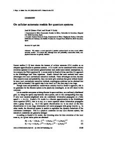
Fig.2. Unit cluster of over lapping of signals during transmission.
In wireless systems, in many situations, there may not be a line-of-sight between the MS and the BS. Therefore, transmitted signals are received from different paths with different delays at the receiver and this causes abrupt increase or decrease in the received signal power. This problem is more troublesome in uplink channel due to the low transmitting power of the MS. In micro zone architecture because of using zones in every cell, Antenna diversity in the BS is used in uplink channel to overcome this problem. Also, the distance between each pair of antennas is atleast several times greater than the transmitted signal wavelength, So that the signal transmission paths would stay independent from each other. Micro zone architecture has some advantages. For example the received SIR is increased by the use of diversity technique. Another advantage is, if users uniformly distributed in a cell then a large number of them are distributed at the regions near to antennas of a cell as compared with the used architecture. Therefore by the use of micro zone architecture, the received SIR is also increased.
(b) sectors at 120o
Fig.1. Sectoring structure of signals for frequency reuse.
one omni-directional antenna at the BS by several directional antennas. Every one of these antennas radiates within a specific sector of the cell. Directional antennas, therefore, minimize interference for a given cell by receiving and transmitting with only a fraction of available co-channel cells, so the QOS will be increased. The degree of interference minimization depends on the amount of used sectors, in general, a sector corresponds to 60° or 120° fig1. (a) and (b). Since each sectorised antenna radiates within a specific sector, each sector is allocated a subset of the frequency channels available for the cell. When sectoring is used, the channels in a particular cell are broken down to sectored groups 60° sectoring reduces the co-channel interference (CCI) by a factor of six, while the 120° sectoring reduces it by a factor of three. In micro zone architecture each of cells is divided into three (or more) zones and each zone has an antenna that is connected by cable or microwave link to the BS of the Cell. Antennas are placed at the outer edge of the cell. Cells are shown by circles, while zones are represented by hexagons circumscribed within each circle fig- (4a). When a MS travels within the cell, its transmitted signal in uplink channel is received by all antennas in a cell and by the use of diversity technique, i.e., maximum ratio combining (MRC), an acceptable level of the received signal is achieved. Another advantage of this architecture is remaining a MS in the same cell with same frequency band as long as it travels from one zone to another within the cell. Therefore, unlike sectoring, handoff is not required when the MS travel zone to zone in the cell, and only the BS switches the signal from one zone to another. In this case, the used antennas are directional and the micro zone architecture is configured similar to used architecture (i.e., it has 1, 3, 5 or 7 cells per cluster).
(a) Regular Hexagon (b) Square Fig. 3.Regular geometrical shapes which can be use in propagation of signals
Also an increase in the received SIR will decrease the outage probability and finally network capacity and performance will be increased. Another advantage is that handoff is not required when the MS travel in a cell. Because of using diversity technique, antenna arrangement, and above mentioned reasons also, the gain of every sectorised antenna is supposed to be 0, which is kept constant during the simulations. In the micro zone system, it is not possible to use omni-directional antennas, because the antennas must be located at the outer edge of any cell and cover only the related zones. However, both 60° and 120° antennas are employed in the micro zone system. The BS antennas for the uplink are assumed to be identical. A. Frequency Reuse station antenna and free space propagation Of course, the actual cellular footprint is determined by the contour in which a given transmitter serves the mobiles successfully. When using hexagons to the model coverage areas, base station transmitters are depicted as either being in the center of the cell (center-excited cells) or on three of the six cell vertices (edge-excited cells). Normally Omni directional antennas are used in center-excited cells and sectored directional antennas are used in cornerexcited cells. Practical considerations usually do not allow base stations to be placed exactly as they appear in the hexagonal layout. Most system designs permit a base station to be positioned up to one-fourth the cell radius away from the ideal location. To understand the frequency reuse concept, consider a cellular system which has a total of S duplex channels available for use. If each cell is allocated a group of k channels (k < S), and if the S channels are divided among N
Muhammad Tahseen Iqbal |III. CELLULAR Architectures
41
cells into unique and disjoint channel groups which each have the same number of channels, The N cells which collectively use the complete set of available frequencies is called a cluster. In above example, the cluster size N, is equal to seven, and the frequency reuse factor is 1/7 since each cell contains one-seventh of the total number of available channels. The total coverage area is divided into clusters. There can be no co-channel interference within a cluster. B. Capacity Let S = the total number of available duplex radio channels for the system, k = the number of channels allocated to each cell (k < S) , N = cluster size. If the S channels are divided among N cells into unique and disjoint channel groups which each have the same number of channels, S = k * N. If a cluster is replicated M times within the system, the total number of duplex channels, C, is given by C = M * S = M *k *N. For a fixed total coverage area (Atotal) and the coverage area Acell of each cell, the number of cells in the system is M × N = Atotal * Acell. C. Comparison of shapes Full coverage of the whole region is necessary without leaving any uncovered spots. We will assume that all cells have the same shape. Cells should have some symmetry (cells can be rotated in place at angles less than one complete rotation without affecting cells layout) Cell shapes that meet the above constraints are equilateral triangle, square and a hexagon. An equilateral triangle is one with all sides having equal lengths and all angles being 60° which can be used for full coverage without leaving any space uncovered fig.5. Other geometrical shape which fulfills the requirements is a square fig.3b. However these shapes couldn’t give optimal coverage area. Hexagon is a shape with six equal sides and angles and is the most efficient cell shapes to cover large regions. Sometimes signal shape is intentionally made non-hexagonal because non‐hexagonal cell shape is the most spread shape compared with regular hexagonal shape fig.3a. As the Signals travels from source in outward normal direction and as they gets farther from the source they gets weaker and weaker due to many factors, one of those factors is destructive interference in those areas where they over-laps as in fig .2 [8]. The most efficient theoretical cell shape that will allow us to provide full coverage to a large area by stacking the minimum number of cells possible ideally is a circle, the best shape because it is the
(a)
(b)
Fig. 4 a) Cluster of overlapping signal structure of hexagon with ensecribed circle. b) Over laped area of signals within sixty degree sector.
natural reach of electromagnetic waves when they are transmi-tted from an Omni directional antenna. However, it is not possible to stack circles near each other and cover the whole region of interest without leaving some gaps. For cell
Fig. 5. Equilateral triangles with assumed dimensions.
shapes, let us observe some points: Boarders of cells are straight lines and cell shapes are polygons (Polygons are geometric shapes with all edges straight lines like equilateral triangles fig. 6, rectangles, pentagons etc. Other symmetrical polygons cannot cover the
complete space, For example, a pentagon fails to cover the complete space; you will need more cells to cover the remaining regions.
Fig. 6. Shape of unit signal cluster in csase of equilateral triangle is used.
D. Most Efficient Cell Shape By studying the above three shapes (equilateral triangle, square , and a hexagon), we see that the hexagon in fig. 4b is the most efficient cell shape because it requires the least number of cells to cover a specific area using hexagons than using triangles or squares [7]. It is the closest to the shape of a circle which is the natural transmission pattern of an Omni directional antenna (the difference between the distances of different points on its perimeter are the smallest with hexagons compared to squares or triangles. IV. INTERFERENCE AND SYSTEM CAPACITY Interference is the major limiting factor in the performance of cellular radio systems. It is a major bottleneck in increasing capacity and is often responsible for dropped calls. Interference is more severe in urban areas, due to the greater RF noise floor and the large number of base stations and mobiles. Interference on voice channels causes cross talk, where the subscriber hears interference in the background due to an undesired transmission. On control channels, interference leads to missed and blocked calls due to errors in the digital signaling. A. Sources of interference There are many sources of interference some of those are If there is another mobile in the same cell, it causes interference. If a call is in progress in a neighboring cell, it may causes interference. A non-cellular system which leaks energy into the cellular frequency band causes interference. If there are other base stations operating in the same frequency band interference occurs (In practice, the transmitters from competing cellular carriers are often a significant source of out of band interference, since competitors often locate their base stations in close proximity to one another in order to provide comparable coverage to customers.) There are two major types of cellular system interference. B. Co-channel interference Cells that use the same set of frequencies in a coverage area (Frequency reuse concept) are called co-channel cells. The interference between signals from co-channel cells is called co-channel interference. Unlike thermal noise which can be overcome by increasing the signal-to- noise ratio (SNR), cochannel interference cannot be combated by simply increasing the carrier power of transmitter. This is because an increase in carrier transmit power increases the interference to neighboring co-channel cells. Co-channel interference can be reduced by separating co-channel cells physically by a minimum distance to provide sufficient isolation due to propagation. C. Adjacent channel interference Interference resulting from signals which are adjacent in frequency to the desired signal is called adjacent channel interference. Adjacent channel interference results from imperfect receiver filters which allow nearby frequencies to leak into the pass band. The problem can be particularly serious while the receiver attempts to receive a base station on the desired channel and if an adjacent channel user is transmitting signals in very close range to a subscriber's receiver. This is referred to as the near-far effect, where a nearby transmitter (which may or may not be of the same type as that used by the cellular system) captures the receiver of the subscriber. Alternatively, the near-far effect occurs when a mobile close to a base station transmits on a channel close to one being used by a weak mobile. The base station may have difficulty in discriminating the desired mobile user from the "bleed over" caused by the close adjacent channel mobile. Adjacent channel interference can be minimized through
Muhammad Tahseen Iqbal |IV. Interference and System Capacity
42
careful filtering and channel assignments. Since each cell is given only a fraction of the available channels, a cell need not be assigned channels which are all adjacent in frequency. By keeping the frequency separation between each channel in a given cell as large as possible, the adjacent channel interference may be reduced considerably. Thus instead of assigning channels which form a contiguous band of frequencies within a particular cell, channels are allocated such that the frequency separation between channels in a given cell is maximized. By sequentially assigning successive channels in the frequency band to different cells, many channel schemes are able to separate adjacent channels in a cell by as many as N channel bandwidths, where N is the cluster size. Some channel allocation schemes also prevent a secondary source of adjacent channel interference by avoiding the use of adjacent channels in neighboring cell sites. If the frequency reuse factor is small, the separation between adjacent channels may not be sufficient to keep the adjacent channel interference level within tolerable limits. D. Factors Effecting Co-Channel Interference. When the size of each cell is the same and the BSs transmit the same power. The co-channel interference ratio depends on the radius of the cell (R), the distance between centers of the nearest co-channel cells (D), where Q = D/R= co channel reuse ratio = the spatial separation between co-channel cells relative to the coverage distance of a cell. Interference is reduced when Q is increased (improved isolation of RF energy from the co-channel cell). Q is related to the cluster size (N) for a hexagonal geometry. V. MODERN SYSTEM Most modern wireless systems are organized into geographic cells, each controlled by a base station cellular radio systems rely on an intelligent allocation and reuse of channels throughout a coverage region. Each cellular base station is allocated a group of radio channels to be used within a small geographic area called a cell. Base stations in adjacent cells are assigned channel groups which contain completely different channels than neighboring cells. The base station antennas are designed to achieve the desired coverage within the cell. By limiting the coverage area within the boundaries of a cell, the same group of channel may be used to cover different cells that are separated from one another by distances large enough to keep interference levels within tolerable limits. The distance between two cells that use the same frequency channels is called the reuse distance. This reuse distance can be computed from link budgets [8]. A. The Concept of Power dissipation in Cellular Systems Cellular phone can no longer demodulate the signals. At that distance, a mobile phone will indicate that there is no service. When two towers are close to each other, the transmitted power from each one enters the coverage area of the other; a cellular phone will connect to the cellular tower from which it receives a stronger signal. Assuming that both towers transmit equal power, the curve at which equal power is received from both towers is a straight line as shown below. When multiple towers are close to each other, a cell phone will communicate with the tower that provides it with the highest power. In practice, cell boarders are never straight lines because of uneven power transmission by different towers, uneven earth surface, the existence of geographical features, trees, or buildings make the cell barriers random in shape. In fact, cell phone companies usually test cell barriers by having some drive around with sophisticated cell phones to determine where cell barriers are located for proper planning.
Fig.7. Transmission of signals in cellular system.
B. Attenuation The attenuation is the decrease of signal strength between the transmitter and the receiver. In air medium, the attenuation is simply inversely proportional to the square of the distance. C. Propagation and Range in a wireless communication System signal to noise ratio In the case of multi-rate systems, Signal to Noise ratio (SNR) plays an important role. The sensitivity of the system mainly depends upon the minimum SNR The signal to noise ratio (SNR) defines the difference of power in between a valid signal and a noise in the receiver system. The SNR should be Minimum to decode successfully the received signal. VI. TRANSMITTED POWER The transmitted power is the strength of the transmissions measured in Watts (or milli Watts). System having a high transmit power consumes more power and demands for a higher rate of power supply. High usage of transmitting power also effects on frequency reuse. Different networks in areas close to each other, tends to affect each other due to high power usage. A. Sensitivity The sensitivity is the measure of the weakest signal that may be reliably heard on the channel by the receiver (it is able to read the bits from the antenna with a low error probability). B. The fading effect The information theoretic analysis of fading channel is one of the major considerations in wireless communication. This interest is motivated by the rapid advances in wireless technology and the need to use scarce resources such as bandwidth and power as efficiently as possible under severe fading conditions. The physical parameters like Walls and floors reflect the signal under transmission and tend to decrease the signal strength, and background noises make it more difficult to demodulate the received message to retrieve back the original message. The channel quality also varies quite a lot over the time as the environment is not static.
Fig.8(a)Sector showing the overlaped area.(b) Sector with Equilateral triangle.
Combined shape of the signal is shown in fig. 2b. When Signals travel in outward normal direction, some areas of circles overlap each other, these overlapping areas causes interference and becomes source of dissipation of energy. In the following way we can calculate those overlapping areas. For a little bit ease if we consider these cells regular hexagonal shape bounded by exterior circles fig. 4a and base station is in the middle of cell When signal travel from BS in outward direction, interference started as signal reaches 2− 3 2
𝑥 away from BS and goes on increasing till radius
becomes
3 2
𝑥. Let the side of the regular hexagon is “x”
Muhammad Tahseen Iqbal |V. Modern System
43
(kilometers) as shown in Fig.3b. Consider also a sector of the circle Shown in Fig. 7b, then area of sector OAB is 60 °
A1= 𝜋𝑥 2 (square kilometers) (1) 360 ° Again in the same sector area of triangle OAB shown in 1 Fig. 8b, can be calculated by the formula , ∆ = 𝑎𝑏 sin 𝜃 2 Where a and b are sides of triangle and 𝜃 is included angle between sides of triangle a and b which is 60° in this case, 1 area of triangle OAB , A2 = 𝑥 2 𝑠𝑖𝑛60° . 2 3 2 𝑥 4
Area of triangle OAB,A2 = (square killometers) Now shaded area in fig. 7a is eq. 1 – eq. 2 . Shaded area in Fig. 8a, A= A1-A2= 𝜋
𝜋 6
3
𝑥2 –
3 4
[6 ]. F. Adachi, , Jan.2001, “Wireless past and future-evolving mobile communication systems”, IEICE Trans. Fundamentals, vol. E84-A, no.1, (pp.55-60). [7]. R.A. Leese, “A unified approach to the assignment of radio channels on a regular hexagonal grid”, IEEE Transactions on VehicularTechnology,vol.46,no.4,(pp.968-980),1997. [8]. Hashmi, R. M., Siddiqui, A. M., Jabeen, M., & Alimgeer, K. S. (2011, July). “Towards secure wireless MAN: Revisiting and evaluating authentication in WiMAX”. IEEE Computer Networks and Information Technology (ICCNIT), 2011 International Conference on (pp. 165-173).
(2)
𝑥 2 square
killometers. A=𝑥 2 ( − ) (square killometers) (3) 6 4 As shaded area in fig. 4b is twice the area “A” Calculated above therefore ,Area of shaded region in Fig.4b 𝜋
3
=2𝑥 2 ( − ) square kilometers. (4) 6 4 As there are twelve overlaping areas of a centeral cell with six outer cell cluster as shown in Fig. 4b. Total over lapping area of central circle with six outer circles fig. 2. of radius “x” 𝐴 = 12𝑥 2 2𝜋 − 3 3 square killometers. (5) 3
Limits of overlapping area are from 𝑥 𝑡𝑜 𝑥. As radius 2 increases overlapped area decreases according to inverse square law because curvature of circular shape of signal gets larger and larger. Decrease in overlapped area of unit cluster of signals consisting of a central hexagon surrounded by six other similar 12 𝑥 1 hexagonal signals= (6) 3 2 𝑑𝑥 (square kilometers). 𝜋
2
𝑥𝑥
Results are graphically shown in fig. 9. VII. CONCLUSION Calculation of amount of overlapping area is important in cellular system as the total amount of signal interference depends on the overlapping area. This amount of signal inteference plays an important role in making the decesion of handoff. A closed form analytical expression is presented in this paper for the calculation of minimum overlapping area without any gap in coverage in which signal interference occures.
Fig. 9. Amount of overlapping area as a function of increasing radius.
REFERENCES [1]. J. G. Proakis, Digital Communications, 4th ed. NY: McGraw Hill, 2000. [2]. Theodore S. Rappaport. Wireless Communications Principles and Practice. Prentice Hall, Upper Saddle River, NJ, USA, 2002. [3]. A. Papadogiannis, D. Gesbert, and E. Hardouin, “A Dynamic Clustering Approach in Wireless Networks with Multi-Cell Cooperative Processing,” IEEE International Conference on Communications, (ICC‘08),2008. (PP 4033 – 4037) [4]. S. Venkatesan, (2007, September) “Coordinating Base Stations for Greater Uplink Spectral Efficiency in a Cellular Network,” IEEE 18th International Symposium on Personal, Indoor and Mobile Radio Communications (PIMRC‘07),(PP 1-5) [5]. Alimgeer, K. S,"A comparison of Interference Cancellation scheme based on QR decomposition and based on MMSE for Space Time Block code in multi-rate multi-user Systems." IEEE Multitopic Conference, 2006. INMIC'06., 2006.(PP:79 – 83)
Muhammad Tahseen Iqbal |VII. Conclusion
44