3496
IEEE TRANSACTIONS ON MAGNETICS, VOL. 49, NO. 7, JULY 2013
Cell Patterning Using Magnetic Concentric Rectangular Thin Films for Biochip Application Tzong-Rong Ger , Chen-Yu Huang , Chia-Wei Chiang , Po-Wei Fu , Keng-Shiang Hu , Yi-Han Peng , and Zung-Hang Wei Department of Power Mechanical Engineering, National Tsing Hua University, Hsinchu 300, Taiwan Institute of NanoEngineering and MicroSystems, National Tsing Hua University, Hsinchu 300, Taiwan Institute of Biomedical Engineering, National Tsing Hua University, Hsinchu 300, Taiwan In this report, magnetic cell patterning is demonstrated through controlling the micromagnetic states in microstructured concentric rectangular ferromagnetic thin films. The number of magnetic nanoparticles entered the cells via endocytosis can be determined by magnetophoresis experiment. In concentric rectangular magnetic films, the effects of cell patterning differ from magnetic films at as-deposited state and at remnant states after applying field. Remnant states of concentric rectangular are proposed for cell patterning. Living cells can be arranged at specific diagonal direction in sequence by selectively changing the magnetic field directions. Index Terms—Cell patterning, magnetic domain walls, magnetophoresis.
I. INTRODUCTION
C
ELL patterning is very important in the field of biomedical engineering, with applications ranging from fundamental biological study to tissue engineering. For normal functional tissues, homotypic cells and heterotypic cells are supposed to be located at correct positions. Therefore, the concept of cell patterning and organizing technology is proposed by Carter et al. [1] which was followed by several publications in this technological area. Various techniques that utilize magnetic fields to control the micro/nano magnetic particles have been proposed, including applying an external magnetic field or using the magnetic field generated from the microstructure. Further, the standard practices of magnetic cell manipulation [2], [3], collection [4], [5], positioning [6] and sorting [7] have been reported in various publications, typically making use of combining micro- or nano-sized superparamagnetic beads and patterned magnetic thin films array. Magnetic cell manipulation with several approaches and methodologies have been demonstrated by several groups in the past including Reich et al. [8] and Whitesides et al. [9]. Our method is to use the magneitc force originating from localized stray fields, which is induced by magnetic thin films, to actively trap the magnetically labeled cells in an ordered position. Previously, we have proposed a design based on controlling magnetic domain walls within zig-zag magnetic film to pattern the cells [10]. The local magnetic force, which results from the high stray field produced by the magnetic domain walls in the remnant state, attracts the cells to some specific positions. We have also demonstrated the magnetic forces produced in the vicinities of domain walls to
Manuscript received November 04, 2012; revised January 09, 2013; accepted January 29, 2013. Date of current version July 15, 2013. Corresponding author: Z.-H. Wei (e-mail:
[email protected]). Color versions of one or more of the figures in this paper are available online at http://ieeexplore.ieee.org. Digital Object Identifier 10.1109/TMAG.2013.2245866
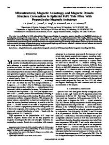
Fig. 1 Illustration of the magnetic cells attracted by the stray fields from the corners of the concentric rectangular element. Insets present the magnetization pattern of head-to-head (HH), tail-to-tail (TT) and head-to-tail (HT) domain walls, respectively.
attract the cells are stronger for head-to-head (HH) or tail-to-tail (TT) domain walls than head-to-tail (HT) domain walls in ferromagnetic zigzag thin films [11]. Therefore, we designed a concentric rectangular structure, inducing head-to-head or tail-to-tail domain walls by magnetizing the structure, hence generating a greater stray field for cell patterning (see Fig. 1). In our study, we begin with conducting the magnetophoresis experiment, quantifying the nano magnetic particles internalized by cells. After concentric rectangular thin films are fabricated, by controlling the positions of induced head-to-head or tail-to-tail domain walls, patterning of cells could be achieved by controlling the positions of induced head to head or tail to tail domain walls. We further confirmed the patterned cells were alive using fluorescence microscopy to observe green fluorescent protein (GFP) expressed by living cells.
0018-9464/$31.00 © 2013 IEEE
GER et al.: CELL PATTERNING USING MAGNETIC CONCENTRIC RECTANGULAR THIN FILMS FOR BIOCHIP APPLICATION
3497
II. EXPERIMENTAL DETAILS A. Sample Fabrication The concentric rectangular ferromagnetic films were prepared using conventional photolithography and lift-off techniques on glass substrates. First, patterns were drawn with chromium metal photomask, and the patterns were defined by electron beam lithography. Two different patterns of concentric rectangular magnetic films were fabricated: 5 rectangles and 10 rectangles, both with 12 uniform line width and 12 interval between lines. An inverse image of the patterns was created on the positive photoresist on top of the glass substrate using the photomask and ultraviolet light exposure with a mask aligner. The patterns were stenciled on the photoresist layer by rinsing the substrate in the developer and deionized water. We used ebeam evaporation system to deposit stacked structures, each stack includes 10 nm of Titanium as adhesive layer and 30 nm of iron, yielding an overall thickness of 200 nm. The thickness was monitored by a quartz crystal and the temperature of the substrate was kept at room temperature. No external fields were present during the deposition. Finally, the photoresist was removed using the lift-off process, leaving the desired structures of concentric rectangular iron magnetic thin film array on the glass substrate. To encapsulate the iron layer, PMMA was spin-coated onto the chips at a nominal thickness of 300 nm [12]. Lastly, the samples were stored in a vacuum-sealed desiccator to prevent the absorption of moisture. B. Cell Culture and Magnetophoresis Test NPC-TW01 cells, which are adherent cells, were cultured in Dulbecco’s modified eagle’s medium (DMEM) containing 1% penicillin and 10% fetal calf serum at 37 and 5% environment. The cells were co-cultured for 24 hours with a diluted concentration of 1 magnetic fluid (Ferrotech 705) consisting of magnetic nanoparticles, each with 10 nm average diameter. In a petri dish, the magnetic nanoparticles entered the cells through endocytosis. The cells that contained magnetic nanoparticles were collected by a permanent magnet and concentrated by centrifugation. The collected magnetic cells were then put in a clean culture medium. Magnetophoresis [13] was used in our study to estimate the number of the magnetic nanoparticles in the NPC-TW01 cells. A permanent magnet was used to provide the constant field gradient. The field gradient applied on the cells leads to different distributions of cell velocities. The magnetic force can be expressed as , the product between the magnetic moment of the magnetic beads and the magnetic field gradient; from Stokes’ law, the viscous force can be expressed as . When the cells move in a constant velocity in the magnetophoresis experiment, the balance between the above two forces holds, and it can be used to estimate the number of magnetic nanoparticles in each cell (1) where is the viscosity of the medium at 37 [14] and R is the average radius of each NPC-TW01 cell.
Fig. 2 Optical microscope image of the nanomagnetic particles successfully patterned onto the structure after magnetizing the concentric rectangular films.
III. RESULTS AND DISCUSSION Fig. 2 shows that the nanomagnetic particles can be successfully patterned onto the structure after magnetizing the concentric rectangular films. The cell velocity in the abscissa axis of Fig. 3 represents the constant velocity of each cell when forces are balanced, as shown in inset on top of Fig. 3. The cell velocity is calculated cell by cell with total amount of 475 cells. The optical microscope images in Fig. 3 show magnetophoretic mobility of labeled cells. The time lapse between two images is 20 sec. is the total magnetic moment of the magnetic nanoparticles in a cell, where is the total number of magnetic nanoparticles per cell, is the ratio of the net magnetization of magnetic nanoparticles to their saturation magnetization , and is the average diameter of each magnetic nanoparticle. An external magnetic field of 110 mT was applied to perform magnetophoresis experiments, by comparing the magnitation curve [15], the c value here was set as 0.8. According to the results obtained in previous literature, the parameter was set as [16]. Therefore, using (1), the number N of magnetic nanoparticles per cell can be estimated to be . Cells co-cultured with magnetic nanoparticle solution does not possess much cyto-toxicity issues by trypan blue exclusion test. Fig. 4 represents the optical microscopy images of the distributions of NPC-TW01 cells on magnetic concentric rectangular structures. For the as-deposited state, the magnetic domain walls are randomly distributed in the magnetic concentric rectangular structures, and it can be observed that the cells are randomly distributed as shown in Fig. 4(a). For the remanent states after applying saturated fields in diagonal direction as shown in Fig. 4(b) (5 rectangles) and Fig. 4(c) (10 rectangles), the magnetic domain walls are located at the corners of the magnetic concentric rectangular structures. According to the previous research [17], the magnetic pole densities of HH or TT domain walls exhibit locally single pole characteristic and the distribution area of the pole density is wide, so the stray field is much larger. In contrast, HT domain walls exhibit locally positive/negative pole characteristic and the distribution area
3498
Fig. 3 Histogram of cell velocity distribution derived from magnetophoresis extracelexperiment. In statistics, a total of 475 cells were recorded in 1 lular concentrations of magnetic nanoparticles. The inset on the top shows the balance between the viscous force and the magnetic force exerted on the magnetic cell. The inset shows magnetophoretic mobility of labeled cells in consecutive optical micrographs. The time lapse between two micrographs is 20 sec.
IEEE TRANSACTIONS ON MAGNETICS, VOL. 49, NO. 7, JULY 2013
Fig. 5 Florescent image of NPC-tW01 cells with GFP expressed patterning on magnetic concentric rectangular structures.
the magnetic labeled cells to specific position. Furthermore, by adjusting the direction of external magnetic field and changing the domain-walls patterns, the pattern of the position of cells can be changed. In terms of fabrication costs, the fabrication only requires respectively one photolithography and magnetic thin films deposition. No etching process is necessary. Also, after magnetizing the chips, cell patterning can be achieved even without any external magnetic field applied. IV. CONCLUSION
Fig. 4 Optical microscope images of the distributions of NPC-TW01 cells on magnetic concentric rectangular structures in (a) its as-deposited state without applying any field and in its remanent state after applying a magnetic field in (b) 5 rectangles, and (c) 10 rectangles.
of the pole density is much narrower, therefore the influence range of the stray field is significantly restricted near the positive and negative poles. Hence the magnetic forces produced in the vicinities of domain walls to attract the cells are stronger for the corners with HH or TT domain walls. Cells could withstand the rinsing steps after cells adhere to samples and nonmagnetic cells could be washed away by slow pipet flow. Furthermore, we used florescent living cell methodology to verify that our experiment was based on living cells pattern control. Fig. 5 shows the florescent image of patterned GFP expressed cells. The NPC cell could adhere to samples after 2–4 hrs of incubation time. Before attaching the patterned cells onto the substrate, we could release the trapping cells from the device with vigorous pipetting. After the patterned cells were attached onto the substrate, cells from the substrate were disaggregated and removed by treatment with detachment solution like Trypsin-EDTA or HyQTase. The proliferation of recollected cell could take at least five days to culture. In our experiment, the stray field generated by domain wall in the patterned magnetic thin films was used to localize
In summary, by controlling magnetic domain walls, the patterning of magnetic cells is demonstrated experimentally. Once the magnetic domain walls are formed by the applied magnetic field, no magnetic field is needed to maintain the magnetization directions of the concentric rectangular structures, and the positions of the domain walls can therefore be fixed. The local magnetic force, which results from the high stray field produced by the magnetic domain walls in the remnant state, attracts the cells to the specific positions. By designing various kinds of patterned magnetic thin films that correspond to different distributions of magnetic domain walls, cells can be effectively manipulated and patterned into various kinds of structures. It is also possible to pattern one type of cells along one of the diagonal line, and then magnetize the rectangle along the diagonal line which is perpendicular to the previous patterned one, therefore another type of cells can be patterned along the second diagonal line, forming a multicell cultivation. This can be very useful for future applications of biochips and tissue engineering. ACKNOWLEDGMENT This work was supported partly by the ROC National Science Council Grant Numbers NSC 99-2112-M-007-016-MY3, NSC 99-2112-M-007-015-MY3 and NSC 101-2623-E-007-012-D. REFERENCES [1] S. B. Carter, “Principle of cell motility: The direction of cell movement and cancer invasion,” Nature, vol. 208, pp. 1183–1187, 1965.
GER et al.: CELL PATTERNING USING MAGNETIC CONCENTRIC RECTANGULAR THIN FILMS FOR BIOCHIP APPLICATION
[2] P. C. Gach, Y. Wang, C. Phillips, C. E. Sims, and N. L. Allbritton, “Isolation and manipulation of living adherent cells by micromolded magnetic rafts,” Biomicrofluidics, vol. 5, p. 032002, 2011. [3] C. P. Lee, H. Y. Tsai, and M. F. Lai, “Rotary transportation of magnetic nanoparticle chains on magnetic thin film array,” Appl. Phys. Lett., vol. 100, p. 264102, 2012. [4] N. Pamme and C. Wilhelm, “Continuous sorting of magnetic cells via on-chip free-flow magnetophoresis,” Lab Chip, vol. 6, pp. 974–980, 2006. [5] T. R. Ger, Y. R. Xu, H. T. Huang, and Z. H. Wei, “A permalloy zigzag structure based magnetic bio-sensor,” J. Appl. Phys., vol. 111, p. 07E506, 2012. [6] K. Ino, M. Okochi, and H. Honda, “Application of magnetic forcebased cell patterning for controlling cell—Cell interactions in angiogenesis,” Biotechnol. Bioeng., vol. 102, pp. 882–890, 2009. [7] D. Robert, N. Pamme, H. Conjeaud, F. Gazeau, A. Iles, and C. Wilhelm, “Cell sorting by endocytotic capacity in a microfluidic magnetophoresis device,” Lab Chip, vol. 11, pp. 1902–1910, 2011. [8] M. Tanase, E. J. Felton, D. S. Gray, A. Hultgren, C. S. Chen, and D. H. Reich, “Assembly of multicellular constructs and microarrays of cells using magnetic nanowires,” Lab Chip, vol. 5, pp. 598–605, 2005. [9] A. Winkleman, K. L. Gudiksen, D. Ryan, G. M. Whitesides, D. Greenfield, and M. Prentiss, “A magnetic trap for living cells suspended in a paramagnetic buffer,” Appl. Phys. Lett., vol. 85, pp. 2411–2413, 2004. [10] M. F. Lai, C. Y. Chen, C. P. Lee, H. T. Huang, T. R. Ger, and Z. H. Wei, “Cell patterning using microstructured ferromagnetic thin films,” Appl. Phys. Lett., vol. 96, p. 183701, 2010.
3499
[11] H. T. Huang, C. Y. Chen, and M. F. Lai, “Cells positioning using magnetic domain walls of ferromagnetic zigzag thin film,” J. Appl. Phys., vol. 109, p. 07B315, 2011. [12] T. R. Ger, C. C. Huang, H. T. Huang, and Z. H. Wei, “Investigation of the magnetization process in a three-dimensional curled up structure,” J. Appl. Phys., vol. 109, p. 07E534, 2011. [13] A. K. A. Silva, C. Wilhelm, J. K. Tabi, N. Luciani, and F. Gazeau, “Cellular transfer of magnetic nanoparticles via cell microvesicles: Impact on cell tracking by magnetic resonance imaging,” Pharm. Res., vol. 29, pp. 1392–1403, 2012. [14] W. Yi, Y. Sun, X. Wei, C. Gu, X. Dong, X. Kang, S. Guo, and K. Dou, “Proteomic profiling of human bone marrow mesenchymal stem cells under shear stress,” Mol. Cell. Biochem., vol. 341, pp. 9–16, 2010. [15] S. A. Rovers, L. A. M. van der Poel, C. H. J. T. Dietz, J. J. Noijen, R. Hoogenboom, M. F. Kemmere, K. Kopinga, and J. T. F. Keurentjes, “Characterization and magnetic heating of commercial superparamagnetic iron oxide nanoparticles,” J. Phys. Chem. C, vol. 113, pp. 14638–14643, 2009. [16] Y. Yang, R. M. Erb, B. J. Wiley, S. Zauscher, and B. B. Yellen, “Imaginary magnetic tweezers for massively parallel surface adhesion spectroscopy,” Nano Lett., vol. 11, pp. 1681–1684, 2011. [17] M. F. Lai, Z. H. Wei, C. R. Chang, J. C. Wu, W. Z. Hsieh, N. A. Usov, and Y. D. Yao, “Magnetization patterns of permalloy square frames,” J. Appl. Phys., vol. 93, pp. 7426–4728, 2003.