Solid-state quantum computer architectures with qubits encoded using single atoms are now feasible given ... encoded on the charge degrees of freedom.
Charge-based quantum computing using single donors in semiconductors L.C.L. Hollenberg*, A. S. Dzurak†, C. Wellard*, A. R. Hamilton†, D. J. Reilly†, G. J. Milburn‡ and R. G. Clark† Centre for Quantum Computer Technology * School of Physics, University of Melbourne, VIC 3010, Australia † Schools of Physics and Electrical Engineering, University of New South Wales, NSW 2052, Australia ‡ School of Physics, University of Queensland, QLD 4072, Australia Solid-state quantum computer architectures with qubits encoded using single atoms are now feasible given recent advances in atomic doping of semiconductors. Here we present a charge qubit consisting of two dopant atoms in a semiconductor crystal, one of which is singly ionised. Surface electrodes control the qubit and a radiofrequency single electron transistor provides fast readout. The calculated single gate times, of order 50ps or less, are much shorter than the expected decoherence time. We propose universal one- and two-qubit gate operations for this system and discuss prospects for fabrication and scale up. PACS numbers: 03.67.Lx, 73.21.-b, 85.40.Ry potentials and find that both one- and two-qubit operations times are well within the relevant decoherence times for the system.
In the search for an inherently scaleable quantum computer (QC) technology solid-state systems are of great interest. One of the most advanced proposals is based on superconducting qubits1, where coherent control of qubits has been demonstrated, and decoherence times measured2. The Kane scheme3, in which qubits are defined by nuclear spin states of buried phosphorus dopants in a silicon crystal, has also attracted considerable attention due to its promise of very long (ms or longer) decoherence times below 1K. Recent advances in single dopant fabrication4-6, together with demonstration of fast single electron transistor (SET) charge detection7,8, bring the Kane Si:P architecture closer to reality. These important results notwithstanding, the demonstration of single spin readout remains a major challenge. Here we consider a Si:P dopant-based qubit in which the logical information is encoded on the charge degrees of freedom. This system, which is complementary to the Kane concept, is not dependent on single-spin readout and, given the present availability of fabrication4-6 and readout7,8 technologies, can now be built. A two qubit gate based on the charge qubit scheme we describe will enable an experimental determination to be made of the key sources of decoherence and error in a nanoscale silicon QC architecture. Such devices therefore provide an important and necessary pathway towards the longer term goal of real-spin Si:P devices.
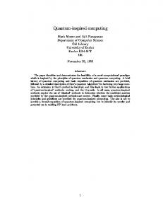
Figure 1. The buried charge qubit. (a) The solid-state charge qubit based on buried dopants D, forming a D-D+ system with one electron, shown explicitly for the case for Si:P. (b) The gated charge qubit showing barrier (B-gate) and symmetry (Sgate) control, together with a single electron transistor (SET) for charge-based readout. (c) One possible choice of logical states |0 and |1 – defined as shown in terms of left and right-localised states.
Semiconductor quantum dot charge-based qubits were first considered in 1995 by Barenco et al.9, where quantum information was encoded in excitation levels, and later by Fedichkin et al.10 for position-based charge qubits in GaAs. Very recently, coherent oscillations have been observed11 in a GaAs double quantum dot providing realisation of a charge-based qubit with decoherence times above 1ns, accessible by existing fast pulse technology. In this paper we assess the potential of Si:P donor-based charge qubits by calculating the energetics and gate operation times for realistic device configurations and gate
The buried donor charge qubit is shown in Figure 1 for the case of P dopants in Si, although a number of other dopant-substrate systems could also be considered, such as GaAs:Si. The lowest two states of a single electron localised by the double well formed by two donor P+ ions give rise to a natural identification of the quantum logic states. External control over the barrier height and potential off-set (or symmetry) is facilitated by B and S gates respectively, placed above the buried P-P+
1
basis of 12 molecular P-P+ states with parameters appropriate to donor electrons in Si.
system, as in Figure 1(b). With appropriate negative bias we can identify localised qubit states with high precision: |0� = |L� and |1� = |R�, as shown in Figure 1(c). Finally, a SET facilitates initialization and readout of the qubit. The Si:P charge qubit will decohere faster than the Kane nuclear spin qubit – however, as the analysis of qubit dynamics will show, the typical gate operation times τop of order 50ps are also commensurately faster than the µs timescale12 of the spin qubit. In what follows we estimate the decoherence time τφ associated with phonons and gate fluctuations, finding τop 1ns11,13. Since such dots possess a similar vulnerability to background charge and may possibly couple more strongly to non-qubit space states than the one-electron Si:P system, we conclude that the coherence time for the buried charge qubit should be at least of order 1ns – certainly sufficient for proof-ofprinciple experiments on small-scale devices. This paper is organised as follows. First, qubit dynamics are analysed to determine the fidelity of qubit states, and voltage pulses required for single-qubit operations. The processes for initialisation and SET readout are then outlined. Two possible qubit coupling schemes are described, and decoherence due to phonon mechanisms, gate fluctuations and charge traps is considered. Finally, fabrication of the charge qubit is described, and a possible scaled up N-qubit architecture is given.
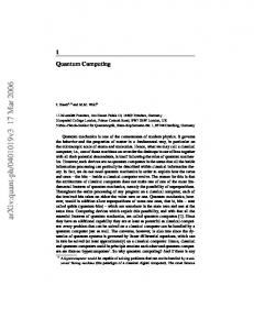
Figure 2. Qubit states and pulse timing. (a) Energy diagram illustrating the evolution of the eigenstates of the system as a function of applied S-gate bias. (b) Pulse timing diagram and SET readout showing the relative timescales for gate operation (τop), SET readout (τmeas), dephasing (τφ) and relaxation (T1).
The key to understanding single qubit gate operations is the effective Hamiltonian HQ describing the dynamics of the P-P+ system in the presence of the S and B gates. In general, HQ will be of the form
We have two choices for the basis of logical qubit states corresponding to the lowest two states being localised or de-localised. Since SET readout is most easily carried out for localised states, we choose initially the configuration with non-zero S-gate bias, which defines our qubit states as |0� = |L� and |1� = |R�. Careful examination of the lowest two eigenstates of HQ shows
H Q = h0 (t ) + h x (t ) σ x + h z (t ) σ z ,
where the σi operate in the basis of qubit states. The qubit logical states are defined by application of reference gate configuration voltages ( VB,VS ) and are manipulated by fast-pulsed deviations (∆VB(t), ∆VS(t)) from the reference configuration. Under these conditions, the time dependent coefficients can then be written as:
that for VS ≈ 0.1V the qubit fidelity is optimal, with mixing of higher states less than 10-4. We discuss later the alternative delocalised basis choice |0� = |A� and |1� = |S�, for which decoherence effects will be less severe. After setting the reference gate configuration to ( VB,VS ) = (0V, 0.1V), the gate bias pulses (∆VB(t), ∆VS(t)) required for qubit control can be read off from HQ. For example, a π/2 rotation over 50ps requires gate bias pulse values of ~(0.40V, +0.10V). The meaning of these values of (∆VB(t), ∆VS(t)) is illustrated in the adiabatic state diagram of Figure 2(a): the double well potential is adjusted to the symmetric position VS = 0, while at the same time raising
hi (t ) = C0(i ) + C S(i ) ∆VS ( t ) + C B(i ) ∆VB (t ) ,
with i=0, x, z. The qubit dynamics are thus determined by the (i )
(i )
parameters C 0 , C S
(i )
and C B which depend explicitly
on the donor separation R and reference biases VB and VS . For the device shown in Figure 1 the spatial dependence of the potentials induced in the silicon substrate due to the gate voltages was modelled using TCAD14 for R = 27nm and these effective Hamiltonian parameters were computed by direct diagonalisation of the Hamiltonian in a
2
the barrier to slow the Rabi oscillations down to the O(50ps) time scales accessible to state-of-the-art pulse generation. Immediately after fabrication the qubit must be preinitialised by removing one of the electrons from the P-P system to form the charge qubit. Using the S and B gates the electron in the right-hand donor well is ionised by a large S gate bias, at the same time the B-gate is raised to effectively isolate the electron in the left-hand well. After pre-initialisation, the SET conductance can be calibrated for the |L� and |R� states. Finally, initialisation of the charge qubit into the left state |0� is effected by simply biasing the S-gate and observing the SET conductance. Prior to readout, the qubit is in a general state |ψ� = c0|0� + c1|1� resulting from a sequence of gate operations with the SET blockaded so that no current flows15,16. To perform a projective measurement a voltage is applied to the SET bias gate tuning it to a conductance peak – the current flow through the device decoheres the charge qubit strongly, and causes a transition in time
Figure 3. Qubit coupling schemes based on the Coulomb interaction. (a) CNOT configuration (b) CPHASE configuration.
Successful operation of quantum devices is contingent on coherence times remaining longer than the time required for arbitrary rotations. Primary sources of decoherence include phonons, Johnson noise on the gates, and materials-related charge noise. At mK temperatures the thermal phonon population is very small but spontaneous phonon emission can still occur. A calculation of LA phonon decoherence for the P-P+ system19 at 100mK concluded that for donor separations
τ meas