UML activity diagrams[2], BPMN[3] or YAWL[4]. We show how the approach works on different properties of business process models, including semantic ...
Checking Properties of Business Process Models with Logic Programming Volker Gruhn and Ralf Laue 1
Chair of Applied Telematics / e-Business? Computer Science Faculty, University of Leipzig, Germany {gruhn,laue}@ebus.informatik.uni-leipzig.de 2
Abstract. Logic programming has been successfully used for reasoning about various kinds of models. However, in the area of business-process modeling it has not yet gained the attention it deserves. In this article, we give some examples how logical programming can be exploited for verifying or finding properties of graphical models that are used by business process modelers, for example event driven process chains (EPC)[1], UML activity diagrams[2], BPMN[3] or YAWL[4]. We show how the approach works on different properties of business process models, including semantic (structural) correctness and modeling style. Keywords: Deductive systems, Business process analysis, Consistency checking
1
Introduction
Business process modelers can chose from various languages like event driven process chains (EPC)[1], UML activity diagrams[2], BPMN[3] or YAWL[4] for drawing a model of a business process (BPM). Often, such BPMs need to be exchanged between different organizations as well as between different editors, workflow engines or process simulators. For the most BPM languages, exchange formats based on the markup language XML are defined. When an XML file that contains a BPM is imported into a tool, input validation should be done in order to make sure that the XML file really contains a syntactically correct BPM. Often, the structural requirements are much more difficult to test than the syntactic restrictions that can be verified using schema languages like the W3X XML Schema. Examples for such more complex syntactic requirements will be shown in Sect. 2. In this paper, we show how logic programming with languages like PROLOG can be used for the validation of syntactic requirements that cannot be validated with XML Schema. Furthermore, we also show how PROLOG can be used for reasoning about more complex properties of a BPM, for example for finding patterns in a model or for checking cross-model consistency. ?
The Chair of Applied Telematics / e-Business is endowed by Deutsche Telekom AG
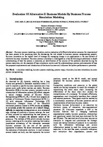
2 customer order arrived
check availability
article is available
article is not available
send article
reject order
order processed
Fig. 1. Simple Business Process modeled as EPC
2
The BPM language EPC and its Exchange Format EPML
In order to keep the examples simple, we will use the notation of EPCs in this paper. EPCs consist of functions (activities which need to be executed, depicted as rounded boxes), events (pre- and postconditions before / after a function is executed, depicted as hexagons) and connectors (which can split or join the flow of control between the elements). Arcs between these elements represent the control flow. The connectors are used to model parallel and alternative executions. There are two kinds of connectors: Splits have one incoming and at least two outgoing arcs, joins have at least two incoming arcs and one outgoing arc. AND-connectors (depicted as ∧ ) are used to model parallel execution. When an AND-split is executed, the elements on all outgoing arcs have to be executed in parallel. The corresponding AND-join connector waits until all parallel control flows that have been started are finished. XOR-connectors (depicted as × ) can be used to model alternative execution: A XOR-split has multiple outgoing arcs, but only one of them will be processed. The corresponding XOR-join waits for the completion of the control flow on the selected arc. Finally, OR-connectors (depicted as ∨ ) are used to model parallel execution along one or more control flow arcs. An OR-split starts the processing of one or more of its outgoing arcs. The corresponding OR-join waits until all control flows that have been started by the OR-split are finished. The EPC elements described above are sufficient for modeling simple business processes like the following one: “When a request from a customer arrives, the
°
°
°
3
availability of the product has to be checked. If it is available, the item will be sent; otherwise the customer will get a negative reply.” Fig. 1 shows this business process modeled as EPC diagram. N¨ uttgens and Mendling[5] defined the XML-based EPC Markup Language (EPML) as a tool-neutral interchange format for EPC business process models. The basic elements of EPML are easy to understand: Events and functions are represented by the tags event and function, connectors are represented by the tags and, or and xor. Every event, function and connector has a unique attribute called id. The control flow is represented by elements named arc. Inside an arcelement, there is an element called flow that names the source and target of the control flow arrow (represented by the ids of the source and target element.) The BPM shown in Fig. 1 is represented by the following EPML file: customer order arrived check availability article is available article is not available send article reject order order processed ... more arc-elements omitted...
4
3
Related Work
Mendling and N¨ uttgens[6] have shown that W3C XML Schema[7, 8] as well as Relax NG[9] can be used for validating rather simple syntactic requirements only. They propose to use the language Schematron[10] which enabled them to validate the most (but not all) syntactic requirements. However, a drawback of this approach is that it requires that the modeler adds redundant information to the model before. For example, for an event without incoming arcs, one has to write
which adds undesirable redundancy to the XML file. An approach that is powerful enough to check even the most advanced syntactic requirements in XML files is the Constraint Language in XML (CLiXML)[11]. Even though the authors of CLiXML admitted in [11] that expressing a graph in the way it is done in EPML makes “things unnecessarily complicated” for CLiXML, it is possible to check all necessary syntactic requirements. The main advantages of our PROLOG based approach over special-purpose solutions like Schematron or CLiXML are that the PROLOG source files used to reason about a model are extremely short and that existing PROLOG systems that offer a lot of interfaces to other programming languages can be integrated into other tools very easily. Another approach that makes use of a special-purpose-built tool has been published by Mammar[12]. Mammar uses the Object Constraint Language (OCL) for specifying required structural properties of UML diagrams an translates the diagrams into the internal representation of the USE tool[13]. Afterwards, this tool can be used for checking the required properties. This work has a lot of similarities with our logic programming-based approach. The related work discussed so far, lies the focus on validating rather “simple” semantic properties. However, logic programming can be used as well for discovering more advanced model properties. For example, it has be used for finding errors related to the consistency between several models[14], locating patterns in a model[15], applying metrics to models[16, 15] and for deciding which diagram version among several alternative possibilities is the best one according to recommended design guidelines[17]. The preceding list of references (which is by far not exhaustive) contains papers that deal with various kinds of models, including UML class diagrams, structure charts and flow diagrams. As far as we know, there is less work on applying the ideas on business process models in languages like EPC or BPMN.
4
Models as Logical Facts
Logic Programming deals with logical facts and logical rules. At first, let’s have one more look at the example model in Fig. 1. The EPML representation of the model contains these lines:
5 order processed
From a logical point of view, this part of the model contains three facts: 1. The model contains an event whose id is 10. 2. The event whose id is 10 has the name “order processed” 3. The model contains an arc from the element whose id is 1 to an element whose id is 2. In PROLOG, all the information that is included in the model in Fig. 1 is written as predicates (that should be self-explanatory) as follows: event(i_1). elementname(i_1,’customer order arrived’). event(i_5). elementname(i_5,’article is available’). event(i_6). elementname(i_6,’article is not available’). event(i_10). elementname(i_10,’order processed’). function(i_2). elementname(i_2,’check availability’). function(i_7). elementname(i_7,’send article’). function(i_8). elementname(i_8,’reject order’). arc(i_1,i_2). arc(i_2,i_4). arc(i_4,i_5). arc(i_4,i_6). arc(i_5,i_7). arc(i_6,i_8). arc(i_7,i_9). arc(i_8,i_9). arc(i_9,i_10). xor(i_4). xor(i_9).
Due to the fact that the interchange format EPML is based on XML, it is very easy to “translate” the EPML file into the PROLOG facts using a short XSLT stylesheet.
5
Terminology and Model Properties as Logical Rules
In the last section we have shown how the logical facts that are contained in a business process model can be extracted from the model. In order to reason
6
about the model, we have to “teach” the PROLOG system something about the terminology used in the domain of process modeling. This means that we have to write some logical rules that specify this terminology. Here are some examples for such rules: connector(I) :- clause(and(I),true) ; clause(or(I),true); clause(xor(I),true). means that we refer to and-connectors, or-connectors and xor-connectors as connectors. no_outgoing_arcs(X) :- not(arc(X,_)). means that for some model element the logical predicate “has no outgoing arcs” holds if there is no arc that originates from this element. endevent(X) :- event(X),no_outgoing_arcs(X). means that we call an event without outgoing arcs an end event. Once we have defined such basic logical predicates, we can ask queries about the model to the PROLOG system. For example, the query endevent(X). would ask for all end events in the model. For our example model, the PROLOG system will answer with X = ’order processed’
6
Applications of the Method
In this section, we show some examples for queries to the PROLOG system that are useful for finding interesting properties of the model. 6.1
Syntactical Correctness
The need for validating the syntactic requirements has been discussed in Sect. 1. For Event-Driven Process Chains, such syntactic requirements have been formalized in the literature [18, 6]. These syntactic requirements specify for example that there must be at least one end event in the model and that the graph formed by the model is antisymmetric (i.e. if there is an arc from node X to node Y than there is not an arc from node Y to node X). The latter property can be checked with the following simple query (the comma means “and” in the PROLOG language): prop4(X,Y) :- arc(X,Y),arc(Y,X).
7
This query prompts the PROLOG system to search for a counterexample: a pair of nodes X and Y for which there is an arc from X to Y as well as an arc from Y to X. If the PROLOG system does not find a counterexample, it answers with “no” which means that the model fulfills the given property. In [19] we have shown that all syntactic requirements that can be found in the literature can be easily verified using only a few lines of PROLOG code. This includes syntactic requirements that could not be validated with the Schematron approach described in [6], for example the requirement that the graph formed by the model must be a coherent graph. 6.2
Separability
When model checking is used for reasoning about a model, it can be useful to separate the model into independent submodels in order to avoid state-space explosion. The question arises, how to decompose a given model into submodels that can be model-checked separately. It is easy to see that “cutting” a model into two separate submodels is possible at some arcs whose deletion would separate the modeled graph into two separate graphs. Such arcs are known as cut-vertices in graph theory, and the parts of the model that forms the separate submodels are called single-entry-single-exit region in compiler theory. Once again, such arcs can be found with a simple PROLOG query. The following example assumes that we have already defined a predicate prop2 that checks the syntactical requirement that the graph must be coherent. The complete source code for such a predicate can be found in [19]. cut_here(X,Y) :- arc(X,Y), (retract(arc(X,Y)),prop2,assertz(arc(X,Y)); (assertz(arc(X,Y),fail))). In order to find out that the arc from X to Y is a cut-vertex, at first we have to require that there is actually an arc from X to Y. Afterwards, we use the PROLOG-clause retract that deletes the fact that such an arc exists from the PROLOG knowledge base. Now, we use the predicate prop2 in order to check whether the new model (that no longer contains the arc X → Y ) is still coherent. If it is not, prop2 should become “true”, and we have found an arc at which we can separate the model into two submodels. The final assertz predicate makes sure that the temporarily deleted fact that there is an arc X → Y will be added to the knowledge base of the PROLOG system again. 6.3
Modeling Style and Modeling Errors
In the field of software development, coding style rules[20] (also known as code conventions) are widely used. They help developers to read and understand source code more quickly, and as a consequence they help to avoid errors. For graphical models, modeling style rules [21] have been established for the same purposes: Such style rules can improve the comprehensibility of a model. This
8
abc
Fig. 2. Bad Modeling Style
is important, particularly for business process models, whose main purpose is to serve as a communication tool. In [22], we have discussed some common style problems found in real-world models. Fig. 2 shows two example style problems that are related to the usage of the OR-connector. In the left example, the entry into the loop should be a XOR-join rather than an OR-join, in the right example, the optional execution of an activity should also be modeled with XOR. Even if both examples in Fig. 2 are not formally wrong, there exist a better way (namely using a XOR-join instead of the OR-join) for modeling the desired behavior, and the latter can help to avoid misinterpretation of the model. It is easy for the PROLOG system to find such style problems. We just have to define the PROLOG predicate path(X,Y,Path) that becomes true if model element Y can be reached from model element Y along a list of elements that is stored in the variable Path. Also we define the predicate join(X) to become true if X is a connector without outgoing arcs (see [19] for the code for both predicates). Using these predicates, we can define a loop entry as a model element X that is part of a loop (i.e. there is a path from X to X) but also has an incoming arc from some element outside the loop: loop_entry(X) :- join(X),path(X,X,Path),arc(Y,X), not(member(Y,Path)). Now we can look for loop entry nodes that are modeled as OR-join, complain about the style rule and suggest replacing the OR-join by the XOR join. In the same way, we can not only find style problems but also reducable model parts (like a sequence of activities that can be reduced to a single activity in order to reduce the state space in model checking) and “hard” errors in the model. An example for such a “hard” error would be a loop entry point modeled as an AND-join which will cause a deadlock. The “causal footprint” approach published in [23] guides the way for finding such errors in a model. The advantage of our approach over other formal methods like model-checking is that with logic programming we can find problems for models that are still incomplete or even without an agreement about the formal semantics of the model[23].
9
6.4
Consistency between Models
Often, a business process is not modeled by a single diagram. Instead, different diagrams are used for depicting different aspects of the business process or the business process model is de-composed into several submodels. Consistency between those different models is obviously an important requirement. Logic programming has successfully be used for such cross-diagram consistency checks[14]. The ideas from [14] and similar papers can easily be adapted for business process models.
7
Conclusions
The work presented in this paper deals with the analysis of several properties of business process models using logic programming. As shown in Sect. 3, the use of logic programming for finding properties of several kinds of models is a well-established research area. For this reason, we do not claim that the general approach presented in this paper is a new one. However, we gave several examples for exploiting the existing ideas for the domain of business process modeling, an area where logic programming has not widely been used in the past. Because the use of logic programming can help to describe statements about models quickly and in a very condensed form (mainly because of the intrinsic backtracking mechanism in languages like PROLOG), we believe that these ideas are helpful for the research on validation of business process models.
References 1. van der Aalst, W.M.: Formalization and verification of event-driven process chains. Information & Software Technology 41 (1999) 639–650 2. Object Management Group: UML 2.0 Superstructure Final Adopted Specification. Technical report (2003) 3. Business Process Management Initiative: Business Process Modeling Notation. Technical report, BPMI.org (2004) 4. van der Aalst, W.M., Hofstede, A.: YAWL: Yet another workflow language. Technical Report FIT-TR-2002-06, Queensland University of Technology, Brisbane (2002) 5. Mendling, J., N¨ uttgens, M.: Exchanging EPC Business Process Models with EPML. In N¨ uttgens, M., Mendling, J., eds.: XML4BPM 2004, Proceedings of the 1st GI Workshop XML4BPM – XML Interchange Formats for Business Process Management at 7th GI Conference Modellierung 2004, Marburg Germany, March 2004. (2004) 61–80 6. Mendling, J., N¨ uttgens, M.: EPC syntax validation with XML schema languages. In: EPK. (2003) 19–30 7. World Wide Web Consortium: XML Schema Part 1: Structures. (2001) 8. World Wide Web Consortium: XML Schema Part 2: Datatypes. (2001) 9. Clark, J., Makoto, M.: RELAX NG Specification. OASIS. 1 edn. (2001) 10. Jelliffe, R.: The Schematron Assertion Language 1.5. Academia Sinica Computing Centre. (2002)
10 11. Jungo, D., Buchmann, D., Nitsche, U.U.: Testing of semantic properties in xml documents. In: Proceedings of the 4th International Workshop on Modelling, Simulation, Verification and Validation of Enterprise Information Systems, Paphos, Cyprus. (2006) 12. Mammar, A.: A formal approach and its tool support for the specification and the verification of structural properties on UML activity diagrams. In: Software Engineering Research and Practice. (2006) 988–994 13. Richters, M., Gogolla, M.: Validating UML models and OCL constraints. In Evans, A., Kent, S., Selic, B., eds.: Proc. 3rd International Conference on the Unified Modeling Language (UML). Volume 1939., Springer-Verlag (2000) 265–277 14. Kielland, T., Borretzen, J.A.: UML consistency checking. Technical Report SIF8094, Institutt for datateknikk og informasjonsvitenskap, Oslo, Norway (2001) 15. Gustafsson, J., Paakki, J., Nenonen, L., Verkamo, A.I.: Architecture-centric software evolution by software metrics and design patterns. In: CSMR ’02: Proceedings of the Sixth European Conference on Software Maintenance and Reengineering, Washington, DC, USA, IEEE Computer Society (2002) 108 16. St¨ orrle, H.: A lightweight platform for experimenting with model driven development. Technical Report TR0503, University of Munich (2005) 17. Tse, T.H., Chen, T.Y., Chan, F.T., Chen, H.Y., Xie, H.L.: The application of Prolog to structured design. Software: Practice and Experience 24 (1994) 659–676 18. N¨ uttgens, M., Rump, F.J.: Syntax und Semantik Ereignisgesteuerter Prozessketten (EPK). In: Promise 2002 - Prozessorientierte Methoden und Werkzeuge f¨ ur die Entwicklung von Informationssystemen. (2002) 64–77 19. Gruhn, V., Laue, R.: Validierung syntaktischer und anderer EPK-Eigenschaften mit PROLOG. In N¨ uttgens, M., Rump, F.J., Mendling, J., eds.: EPK 2006, Gesch¨ aftsprozessmanagement mit Ereignisgesteuerten Prozessketten, 5. Workshop der Gesellschaft f¨ ur Informatik e.V. (GI). (2006) 69–84 20. Kernighan, B.W., Plauger, P.J.: The Elements of Programming Style. McGrawHill, Inc., New York, NY, USA (1982) 21. Ambler, S.W.: The Elements of UML Style. Cambridge University Press (2003) 22. Gruhn, V., Laue, R.: How style checking can improve business proces models. In: Proceedings of the 4th International Workshop on Modelling, Simulation, Verification and Validation of Enterprise Information Systems, Paphos, Cyprus. (2006) 23. van Dongen, B., Mendling, J., van der Aalst, W.: Structural patterns for soundness of business process models. EDOC (2006) 116–128