of a shale in contact with a drilling fluid (Mody and Hale, 1993; Oort et al., 1996; Tan et al. .... Equations (2), (4), and (5) can be combined with the deviatoric elas-.
CHEMOPOROELASTIC PARAMETER IDENTIFICATION OF A REACTIVE SHALE Emmanuel Detournay University of Minnesota, USA & CSIRO, Australia
Joel Sarout University of Minnesota, USA
Chee Tan CSIRO, Australia
Jean Caurel Total, France
Abstract
1.
This paper is concerned with the experimental identification of some chemoporoelastic parameters of a reactive shale from data obtained in pore pressure transmission - chemical potential tests. The parameter identification is done by matching the observed pressure response with a theoretical solution of the experiment. This solution is obtained within the framework of Biot theory of poroelasticity, extended to include physico-chemical interactions. Results of an experiment on a Pierre II shale performed in a pressure cell are reported and analyzed.
Introduction
The so-called pore pressure transmission-chemical potential test is used in the petroleum industry to assess the osmotic membrane efficiency of a shale in contact with a drilling fluid (Mody and Hale, 1993; Oort et al., 1996; Tan et al., 1998; Charlez et al., 1999). It is motivated by the need to assess the capacity of improving the stability of a borehole in a chemically active shale by increasing the salt concentration of the drilling fluid. In this test, a saturated cylindrical sample of shale is subjected
1
2
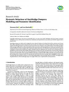
Figure 1.
Principle of the pressure transmission-chemical potential test
sequentially to a hydraulic and a chemical loading on the upstream end of the sample (z = 0), with the downstream end (z = L) connected to a closed reservoir, see Figure 1. The fluid pressure in the reservoir is monitored during the test. The hydraulic loading consists of applying a pressure pm at z = 0 with the solution used during the saturation phase. In the chemical loading the end z = 0 is placed in contact with a solution of a different salt concentration but at the same hydraulic pressure pm . During both loading phases water and salt ions move through the shale sample, driven by differences in pressure and salt concentration between the upstream and downstream reservoir solutions. The main outcome of the experiment is the determination of the membrane efficiency coefficient, a parameter which quantifies the departure of the shale from an ideal osmotic membrane (for which movement of the salt ions is completely impeded). This parameter is determined from the maximum pressure drop (with respect to pm ) in the downstream reservoir during the chemical loading phase. In this paper, we analyze this experiment within the framework of Biot theory of poroelasticity, extended to include physico-chemical interactions, and study the parameters that are influencing the fluid pressure response in the downstream reservoir due to hydraulic and chemical loadings.
2.
Chemoporoelasticity
The Biot theory of poroelasticity (Detournay and Cheng, 1993; Coussy, 1995) can be extended to account for the physico-chemical interactions taking place between the dissolved salt, pore fluid, and a chemically
Chemoporoelastic Parameter Identification of a Reactive Shale
3
active shale (Sherwood, 1993; Sherwood, 1994). For example, a sample of reactive shale surrounded by a fluid initially in thermodynamic equilibrium with the saturating fluid experiences a contraction (ε < 0) accompanied by a decrease of fluid content (ζ < 0) if the salt concentration of the surrounding fluid increases (∆x > 0). These mechanical and hydraulic effects are a consequence of the electrical interaction between the electrolyte and the negatively charged clay platelets at the microscale (Coussy et al., 1999). The volumetric constitutive equations for a chemoporoelastic material can be formulated in terms of the “stress” S = {σ, p, π} and the “strain” E = {ε, ζ, θ}, i.e., in terms of the mean Cauchy stress σ, pore pressure p, osmotic pressure π, volumetric strain ε, variation of fluid content ζ, and relative increment of salt content θ. Note that the stress and strain are measured from a reference initial state where all the “stress” fields are equilibrated. The osmotic pressure π is related to the change in the solute molar fraction x according to π = N ∆x where N = RT /υ is a parameter with dimension of a stress, which is typically of O(102 ) MPa (with R = 8.31 J/K·mol denoting the gas constant, T the absolute temperature, and υ the molar volume of the fluid). The solute molar fraction x is defined as ms /m with m = ms + mw and ms (mw ) denoting the moles of solute (solvent) per unit volume of the porous solid. The quantities ζ and θ are defined in terms of the increment ∆ms and ∆mw according to ζ = υw ∆mw + υs ∆ms ,
θ=
υ υ ∆ms − ∆mw xo 1 − xo
(1)
where υw and υs denote the molar volume of the solvent and the solute, respectively and where xo is the reference salt molar fraction (e.g. at the initial state). For an ideal solution, υ = (1 − x)υw + xυs . The volumetric constitutive relationships can be written as C bC −αbC ε σ Sσ p −βSσ ζ = bC (2) π −αbC −βSσ γ θ
The set of constitutive parameters contains the (drained) elastic volumetric compliance C and two poroelastic constants: the Biot stress coefficient b, and the unconstrained storage coefficient Sσ = ∂ζ/∂p|σ which can be expressed as Sσ = bB −1 C (Wang, 2000), where B is the Skempton pore pressure coefficient. The other three parameters, α, β, and γ quantify the physico-chemical interactions. Both α and β are constrained to vary from 0 when there is no chemical interaction to 1 when the salt ions are trapped in the pore network (this limiting case is
4 referred to as the “perfect ion exclusion membrane model”). The coefficient γ can simply be approximated by γ ' xo /n, where n is the porosity of the shale. Next, we introduce the specific discharge q and the relative solute flux r as υ υ q = υw Iw + υs Is , r = Is − Iw (3) x 1−x where Iw and Is are mass fluxes of solvent and solution, expressed in number of moles crossing a unit surface of porous rock per unit time. Hence, the transport equations can be rewritten as Dc ∇π (4) N where κ is the mobility coefficient defined as the ratio of the intrinsic permeability k over the dynamic viscosity µ, and R is a so-called reflection coefficient. The ion diffusion coefficient Dc is of similar nature than the classical coefficient that appears in Fick’s law (Kondepudi and Prigogine, 1998). However, Dc is smaller than the Fick’s coefficient, as it must account for the extra “resistance” associated with the tortuous path to be taken by the salt ions as they diffuse in the shale pore network (Sherwood and Craster, 2000). Note that 0 ≤ R ≤ 1, with the lower bound corresponding to the limiting case of no chemical interaction and the upper bound corresponding to the ideal ion exclusion membrane model. In terms of q and r, the mass balance laws take the simple form q = −κ∇p + Rκ∇π,
˙ ∇ · q = −ζ,
r = Rκ∇p −
∇ · r = −θ˙
(5)
Equations (2), (4), and (5) can be combined with the deviatoric elasticity equation and the equilibrium equations to form a set of field equations consisting of a Navier-type equation and two coupled diffusion equations. For the class of problems characterized by an irrotational displacement field with chemical and hydraulic loadings only, the two coupled diffusion equations simplify to Ahh Dh ∇2 p + Ahc Dh ∇2 π =
∂p ∂π , Ach Dh ∇2 p + Acc Dh ∇2 π = ∂t ∂t
(6)
where ϕ − CR Cψω − Rϕ C−R ψω − CR , Ahc = , Ach = , Acc = 2 2 2 ϕ−C ϕ−C ϕ−C ϕ − C2 (7) Two new numbers C and ϕ have been introduced to characterize the chemomechanical interactions Ahh =
C = α − (α − β) χ,
ϕ = γψ − α2 (χ − 1)
(8)
Chemoporoelastic Parameter Identification of a Reactive Shale
5
In the above, ω = Dc /Dh is the ratio of the chemical to the hydraulic diffusivity, ψ = 1/N S and χ = Sσ /S ≥ 1 with S = b [η/G + (1/B − b) C] denoting the poroelastic oedometric storage coefficient (Wang, 2000), η = b(1 − 2ν)/2(1 − ν) is a number defined over the interval [0, 1/2], G is the shear modulus, and ν is the Poisson ratio. Generally, ψ = O(10), ϕ = O(1), and ω = O(10−2 ). If the fluid and solid phases can be assumed to be incompressible compared to the skeleton, S ' η/G in which case ψ ' G/ηN and ϕ ' γG/ηN . Also since α = β = 0 for a chemically inert rock and α = β = 1 in the case of an ideal ion exclusion membrane model, 0 ≤ C ≤ 1 with C ' α near the two bounds. However, there are restrictions on the parameters, namely (ϕω − R2 )(ψ − C 2 ) > 0 (which in practice implies that R2 < ϕω if ϕω < 1) to guarantee that the smallest eigenvalue of the matrix of coefficients A0 s is positive, as the diffusion equations would be ill-posed otherwise. Once p and π have been determined for a hydraulic and/or a chemical loading, then the volumetric strain can be computed according to ε = η(p − απ)/G.
3.
Mathematical Model of Experiment
In order to facilitate the modeling as well as the physical interpretation of the pressure transmission - chemical potential test, the loading is decomposed into two fundamental modes corresponding to a hydraulic and a chemical perturbation. The upstream boundary conditions at z = 0 for each of the loading modes can then be written as hydraulic: p = σh H (t) , π = 0; chemical: p = 0, π = σc H (t)
(9)
where H (·) is the Heaviside function and σh = pm − po and σc = πm − πo are the characteristic stresses for the hydraulic and the chemical mode, respectively (with subscript o denoting an initial field). The existence of a fluid reservoir of volume Vd at the downstream end of the sample translates into the following boundary conditions at z = L Bhh ∇p + Bhc ∇π =
L L p, ˙ Bch ∇p + Bcc ∇π = π˙ Dh Dh
(10)
where the coefficients Bhh , Bhc , Bch and Bcc are linearized with respect to the mean molar concentration c¯s of the salt and the corresponding value of the osmotic pressure π ¯ , i.e., Bhh = −ξ, Bhc = ξR, Bch = Bcc =
ξ¯ π [(1 − c¯s vs ) R − 1] , Kf
ξ¯ π [R − (1 − c¯s vs ) ψω] Kf
(11)
6
Figure 2. Evolution of the reservoir pressure for a hydraulic and a chemical loading. The pressure is scaled by the corresponding characteristic pressure while time is scaled according to the diffusion characteristic time Th .
The parameter ξ = V SKf /Vd (with Kf denoting the fluid bulk modulus) encapsulates the influence of the experimental set-up. The coupled diffusion equations (6) together with the boundary conditions (9) and (10) can be solved in close form in the Laplace transform space, and numerically inverted to the time domain. At early time, the solution behaves according to the solution for a semi-infinite domain. At large time, the solution corresponds to the solution of the membrane problem (Sherwood and Craster, 2000), where only the jumps of p and π across the sample are of relevance. In the membrane mode, the two fields p and π vary linearly along the sample as they are equilibrated. The large time solution evolves according to a time scaled by the reservoir characteristic time Tr = L2 Vd /κV Kf , which is a function of the hydraulic storage of the reservoir. The parameter ξ, which enters into the downstream boundary conditions, can actually be interpreted as ξ = Th /Tr , where Th = L2 /Dh is the hydraulic diffusion time scale. When ξ À 1, there exists an intermediate asymptotic behavior corresponding to the zero-flux solution at z = L. When ξ ¿ 1, the solution is essentially the membrane solution. Figure 2 illustrates the evolution of the downstream reservoir pressure in response to a hydraulic and a chemical loading. The chemical response is characterized by a pressure drop taking place over a time scale similar to the hydraulic response and a return to equilibrium over a time scale that reflects ionic diffusion throughout the sample. Interestingly, the downstream pressure response is hardly affected by the constitutive parameters α, β, and γ and depends essentially on Dh , Dc , ξ, and R. In fact, the minimum reservoir pressure pmin reached during chemical loading is approximately given by pm − pmin ' (πm − πo ) R (with a strict equality if the solution behaves according to the membrane
Chemoporoelastic Parameter Identification of a Reactive Shale
7
Figure 3. Downstream fluid pressure response for a pore pressure transmission test with a Pierre II Shale, for successive hydraulic and chemical loading (experimental data and matched theoretical response).
solution). Note that pmin (and thus the interpreted R) is virtually independent of the experimental set-up (as embodied in the parameter ξ) and of the sample length.
4.
Results and Parameter Identification
A series of experiments on Pierre II shale (a shale from the Rocky Mountains in Colorado) has been carried out with the Membrane Efficiency Screening Equipment (MESE) in the laboratory of CSIRO Petroleum, Australia. The samples had a diameter of 25.4 mm and a length of either 13 mm or 25 mm. The saturation stage was conducted with a pressure po of about 10 MPa applied on the upstream end of the sample with Pierre II shale simulated pore fluid. The results of one of the experiments is shown in Figure 3. This particular experiment was conducted on a sample with a length L = 13 mm, for a hydraulic load σh ' 4.2 MPa applied for about 4 days and a chemical load σc ' 7.1 MPa applied for about 3 days (and stopped once the minimum downstream pressure was reached). The chemical loading resulted from increasing the NaCl concentration of the solution from 3.9 wt % to 16.7 wt %. The experimental set-up is characterized by ξ ' 5.1, corresponding to Vd ' 4 mm3 . Identification of the parameters by matching the theoretical and experimental downstream pressure gives R ' 0.27, Dh ' 7.2 · 10−9 m2 /s, and Dc ' 4.3 · 10−10 m2 /s. A comparison between the theoretical and experimental downstream pressure response is shown in Figure 3.
8
5.
Concluding Remarks
A mathematical model of the pressure transmission - chemical potential experiment indicates that the two diffusivities Dh and Dc and the reflection coefficient R can robustly be identified from the downstream pressure response. The analysis also confirms the experimental practice of identifying R with the membrane efficiency coefficient deduced from the minimum of the downstream pressure (Oort et al., 1996; Tan et al., 2002) whose justification is based on simplified considerations.
Acknowledgments Support for this research has been provided by Total, France and CSIRO, Australia. This support is gratefully acknowledged.
References Charlez, P. A., Pradet, V., Onaisi, A., and Gregoire, M. (1999). How to manage wellbore stability in the viking graben tertiary shales by using mud systems environmentally friendly? (SPE/IADC 52865). In SPE/IADC Drilling Conf., pp 317—325. Coussy, O. (1995). Mechanics of Porous Continua. John Wiley & Sons., New York. Coussy, O., Dangla, P., Dormieux, L., and Lemarchand, E. (1999). A two-scale modeling of a swelling clay. Journal de Physique, 9:Pr9.21—Pr9.31. Detournay, E. and Cheng, A.-D. (1993). Comprehensive Rock Engineering, volume 2, chapter 5: Fundamentals of Poroelasticity, pages 113—171. Pergamon, New York. Kondepudi, D. and Prigogine, I. (1998). Modern Thermodynamics : From Heat Engines to Dissipative Structures. Wiley. Mody, F. K. and Hale, A. H. (1993). A borehole stability model to couple the mechanics and chemistry of drilling fluid interaction. In Proc. SPE/IADC Drilling Conf., pages 473—490. Oort, E. V., Hale, A. H., Mody, F. K., and Roy, S. (1996). Transport in shales and the design of improved water-based shale drilling fluids (SPE 28309). SPE Drilling & Completion, pages 137—146. Sherwood, J. D. (1993). Biot poroelasticity of a chemically active shale. Proc. Roy. Soc. London, Ser. A, 440:365—377. Sherwood, J. D. (1994). A model of hindered solute transport in a poroelastic shale. Proc. Roy. Soc. London, Ser. A, pages 679—692. Sherwood, J. D. and Craster, B. (2000). Transport of water and ions through a clay membrane. J. Coll. Interf. Sci, 230:349—358. Tan, C. P., Drummond, C. J., Mody, F. K., and Tare, U. A. (2002). High membrane efficiency water-based drilling fluids: Alternatives to invert emulsion fluids for drilling troublesome shale formations. In SPE Asia Pacific Oil and Gas Conference and Exhibition, Melbourne, Australia. Tan, C. P., Rahman, S. S., Richards, B. G., and Mody, F. K. (1998). Integrated rock mechanics and drilling fluid design approach to manage shale instability, SPE 47259. In Proc. SPE/ISRM Eurock’98. Wang, H. F. (2000). Theory of Linear Poroelasticity. Princeton University Press.