Circuit Optimization using Device Layout Motifs Yang Xiao∗ , Martin A. Trefzer∗ , Scott Roy† , James Alfred Walker∗ , Simon J. Bale∗ and Andy M. Tyrrell
∗
∗
Intelligent Systems Group, Department of Electronics, University of York, Heslington, York, YO10 5DD, UK Email: {yx664, martin.trefzer, james.walker, simon.bale, andy.tyrrell}@york.ac.uk † Device Modelling Group, Department of Electronics and Electrical Engineering, University of Glasgow, Glasgow G12 8LT, UK Email:
[email protected] Abstract—As technology reaches atomic scales, circuit performance is significantly affected by the variability of electrical properties within transistors such as random dopant fluctuation (RDF), line edge roughness (LER), and layout driven variations. This increases pressure on designers to find methodologies that more effectively mitigate the impact of device parameter fluctuations and improve circuit performance. In this paper, a novel alternative layout style of devices is proposed: an Oshaped device layout motif. A 3D O-shaped device simulation including LER variability source is performed using TCAD simulation in order to investigate and exploit the variability characteristics of O-shaped devices at both device level and circuit level. The corresponding statistical variability models enabling efficient circuit-level simulations using SPICE are extracted from TCAD simulation results. In order to further explore this novel device layout motif’s impact on circuit design, a number of logic gates are used as candidates which are constructed using this novel device. The experimental results show that the worse case delay of logic gates can be reduced through mixed combinations of O-shaped devices and regular devices. At the same time, effects of variability on propagation delay can be mitigated.
I.
I NTRODUCTION
The intrinsic variability of electrical properties of aggressively scaled MOSFETs has become a significant challenge in integrated circuit design. This has increasingly promoted designers to find novel design methodologies that more efficiently mitigate the impact of device parameter fluctuations and improve circuit performance and stability. In order to achieve this goal, new device structures and materials have been suggested, and in some cases introduced, to enhance the robustness of circuits and improve their performance [1]–[2]. However, conventional bulk CMOS devices are still foundational to the semiconductor industry and extensively used in current fabrication processes. An alternative to adopting new technologies to minimize the effects of transistor variation and improving circuit performance could be through technology optimization of traditional devices, for example, by optimising the physical layout style of devices within circuit designs [3]. Layout driven variation has been extensively discussed in the literature, for example, intrinsic mis-match reducing the active area [4], gate line edge roughness (LER) affecting the doping profile [5] and stress effects induced by shallow trench isolation (STI) [6]. Of course, the physical layout of devices is also a key to nominal device performance, and thus circuit performance [7]. Typically, in order to gain the fabrication advantages of regularity, the layout of single devices or basic transistor groupings are collected in a small set of device “motifs”, with wider devices or more complex device groups being formed by the combination of these motifs. It is important to
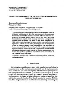
Fig. 1. Proposed O shape device. Top view (upper left), Front view (upper right), Side view (lower left), 3D view (lower right)
investigate the nominal performance and electrical variability of such motifs, both to give designers information on the variability performance of current designs, but also to allow future optimisation of motifs and circuits. We have developed a methodology to extract variability information from complex device structures, pass that information to circuit simulators, and extract relevant circuit parameters. In this paper we apply this methodology to a complex device layout, an irregular O-shaped motif shown in Fig. 1. 3D statistical simulation is performed on this layout motif to evaluate its device characteristics, and then corresponding statistical device BSIM models extracted to allow circuit level simulation. In order to investigate the impact of such a device layout motif on the performance of a circuit, various logic gates are used as simple test candidates, constructed both using the O-shaped device layout motif and with traditional, regular device motifs. The rest of this paper is organized as follows: Section II describes a 3D device layout motif statistical device simulation and corresponding statistical modelling. To investigate the effects of the device layout motifs are on circuit designs, a set of simple logic gates are constructed using the device layout motifs and tested. The corresponding experiment methodology, results and analysis are presented in Section III. Finally,
Section IV provides some conclusions and suggests future work. II.
D EVICE L AYOUT M OTIFS
A. Statistical TCAD Simulation of Device Layout Motifs Device layout motifs can be used to characterize and observe the effects of different sources of intrinsic variability, and how characteristics of variability are affected by the layout of the transistor. The two main sources of intrinsic variations, random dopant fluctuations (RDF) and line edge roughness (LER), result in increased variability that have a significant effect on the transistor characteristics in bulk CMOS transistors [8]–[10]. In order to accurately model the effects of intrinsic variations of a device layout motif, a 3D TCAD model of the device layout motif is created and simulated into which a source of LER variability has been introduced. Methodologies for modelling LER are described extensively in [9]–[10]. The method adopted in this paper is taken from [10] and considers the use of power spectral density (PSD) corresponding to the Gaussian autocorrelation function to generate gate edge roughness. Two important parameters of the method which are used to characterize the Gaussian autocorrelation function are: the standard deviation of the transversal magnitude to the gate edge (RMS amplitude) ∆ and the correlation length Λ. The Gaussian autocorrelation function SG (k) is defined as: √ k 2 Λ2 SG (k) = π∆2 e−( 4 ) (1) k = i(2π/N dx)
Fig. 2. The roughness of gate edge is generated using PSD method. The top subfigure shows the mathematical calculation gate edge line. And the application of the mathematical calculated line edge result in TCAD device structure is depicted in the bottom subfigure.
(2)
where dx is the discrete spacing used for the gate edge and 0 ≤ i ≤ N/2. More details of this method are described in [10]. The correlation length is set to Λ = 12 nm and the RMS is ∆ = 2 nm, as this is typical for 50 nm technology. Fig. 2 gives an example of random line generated by this method. In this paper, only an O-shaped device layout motif is discussed. However, the techniques described are generic and several alternative layout devices are currently being developed. For example, T-shaped, H-shaped, and long diffusion area TABLE I.
TCAD DEVICE SIMULATION PARAMETERS
Parameter
Description
Lg [nm] W [nm]
Length Width (Regular device) Width (O shaped device) Active area (Regular device) Active area (O shaped device ) Footprint of regular device Footprint of O shaped device Width of the device spacer Width of the device S/D Substrate thickness Thickness of the gate oxide Concentration of the body/channel doping Concentration of polygate doping Concentration of S/D doping Concentration of extension doping Depth of the S/D doping junction Depth of the extension doping junction
ActiveArea [µm2 ] Area [µm2 ] Lsp [nm] Lsd [nm] Hs [nm] Tox [nm] Na [cm−3 ] N d po [cm−3 ] N d sd [cm− 3] N d ex [cm−3 ] Xj sd [µm] Xj ex [µm]
Value 50 80 160 0.036 0.096 0.036 0.117 80 200 500 2 2 × 10¹⁸ 1 × 10²⁰ 1 × 10²⁰ 2 × 10¹⁹ 0.1 0.02
Fig. 3. Regular device. Top view (upper left), Front view (upper right), Side view (lower left), 3D view (lower right)
devices. The methods and techniques described here provide a basis for further investigation of these motifs. A 3D O-shaped device based on a 50 nm technology is created and simulated using the Synopsys technology computer-aided design (TCAD) software Sentaurus [11], to obtain the characteristics of the Oshaped device layout motif. Simultaneously, a regular layout device (shown in Fig. 3), which is based on the same 50 nm process, is created and simulated as a reference device to help verify the design flow and interpret results obtained. A comparison of the I − V characteristics for these two devices from the results of the TCAD simulations is shown in Fig. 4. As suggested by these plots, the O-shaped device layout motif and regular device have very similar I − V characteristics for similar size devices, in terms of length and
Fig. 5. The threshold voltage and leakage current variability distribution of 300 device layout motif samples. The PMOS device variability distribution is shown in the left sub-figure, and the right sub-figure depicts the NMOS device simulation result.The O device has smaller variability distribution on threshold voltage and leakage current than regular device. This means that the O device will gain for device variability mitigation.
Fig. 4. I-V characteristic of Regular device and O-shape device layout motif measured at high drain voltage condition. Verifying that both devices have similar electrical characteristics, both having similar geometries with W=160nm and L=50nm.
width. This suggests that the regular and O-shaped devices are interchangeable in circuit designs. However, the large size transistor is generally replaced by the parallel small size transistor structure in the circuit level design. Thus, the regular device adopts the small size (W = 80 nm) rather than large size (W = 160 nm) in the experiments presented. In order to include and further characterize variability in these devices, a number of statistical 3D device samples with different gate edge lines are simulated using TCAD. The results for threshold voltage and leakage current variability distributions of 300 Oshaped and regular device layout motif samples are shown in Fig. 5. The device simulation parameters used in this experiment are listed Table I. Although TCAD simulation improves the accuracy of results, especially for complex device structures, an significant amount of time is required for obtaining good accuracy, particularly in the case of circuit level simulation [12]. Alternatively, SPICE simulation also provides accurate simulation results with shorter simulating time on circuit level simulation. Thus, for efficiently applying regular device and O-shaped device layout motif in circuit simulation, the corresponding device layout motif BSIM models are extracted by a novel two step evolution strategy BSIM model extraction tool described in [12].
Fig. 6. The statistical I-V characteristic of NMOS regular device are simulated proposed method. The pure model simulation result is shown by red line, and the statistical variability simulation results are depcited by blue lines.
B. Statistical BSIM Variability Model for Device Layout Motifs A statistical variability BSIM model is developed for each device layout motif in order to characterise the effects of variability on a circuit using the different device layout motifs. Traditionally, the process of variability model generation selects one or more device variability parameters such as threshold voltage, offset voltage, low-field mobility [13]-[14] to generate a set of variation values following a Gaussian distribution and injects these variations into a pure model that previously had no variability effects. Although more accurate simulation results are provided by the use of the multiply variation of process parameters modelling the variability of a device, the model generation process also becomes more complex due to the need to measure each of variation parameters distribution. For the sake of the simplicity only threshold voltage is applied to generate variations in these experiments. According to [15], the threshold voltage parameter is assumed to have a Gaussian distribution. A variation value, based on Gaussian distribution and the need of corresponding Gaussian parameters extracted from TCAD device statistical simulation results, to be directly injected into the pure device layout motif BSIM model enables variability to be included in the device layout motifs. For example, the statistical variability of I-V characteristic of NMOS regular device (1000 samples) using above mentioned method is shown in Fig. 6.
TABLE II. T HE EXHAUSTIVE SET OF DEVICE COMBINATIONS FOR THE NAND AND NOR LOGIC GATES . Mx REFERS TO A SPECIFIC TRANSISTOR POSITION IN EACH LOGIC GATE . AT EACH POSITION , THE USE OF A REGULAR DEVICE LAYOUT MOTIF IS SIGNIFIED BY ‘0‘, AND THE USE OF AN O- SHAPED DEVICE LAYOUT MOTIF IS SIGNIFIED BY ‘1‘. Index
M0:M1:M2:M3
Index
M0:M1:M2:M3
1 2 3 4 5 6 7 8
0 0 0 0 0 0 0 0
9 10 11 12 13 14 15 16
1 1 1 1 1 1 1 1
: : : : : : : :
0 0 0 0 1 1 1 1
: : : : : : : :
0 0 1 1 0 0 1 1
: : : : : : : :
0 1 0 1 0 1 0 1
: : : : : : : :
0 0 0 0 1 1 1 1
: : : : : : : :
0 0 1 1 0 0 1 1
: : : : : : : :
0 1 0 1 0 1 0 1
B. Result Analysis To ensure more accurate and efficient characterization of the effects of the O-shaped device layout motif on circuit designs, 1000 statistical circuit samples covering LER source of variation for each circuit combination using different motifs are simulated. Fig. 9 shows a box and whisker plot of the statistical simulation results and depicts the relationship of the various layout motif combinations used in the NAND and NOR gates and the impact of variability upon their corresponding worse case propagation delay. In order to spot interesting effects of the various motif combinations more easily, both of the results for the NAND and NOR gates are sorted into 4 groups based on their worse case delay (the sorted solution groups are listed in Table IV). Table V also lists the statistical variability analysis results for the NAND and NOR logic gates for each of the four groups. According to these results, the NAND and NOR gates have a faster mean delay and smaller standard deviation in group A, where transistor M0 and transistor M1 use the Oshaped device layout motif. This suggests O shaped devices can provide benefits to mitigate the effects of variability upon circuit performance (in terms of speed). It is also worth noting that the results show a circuit built using a mixture of device layout motifs has improved performance compared with a circuit using only a single type of device layout motif.
Fig. 7.
The basic logic gates transistor level schematic
III.
E XPERIMENT AND R ESULT A NALYSIS
A. Experiment Set-up An exhaustive test using all possible combinations of the O-shaped and regular device layout motifs to build two basic logic gates (2 input NAND and NOR) are performed in order to verify the influence of the device layout motif on the performance of each logic gate. The transistor level schematics for the NAND and NOR logic gates are illustrated in Fig. 7. Both logic gates consist of four transistors and therefore have the same set of device combinations (listed in Table II). For both experiments, the O-shaped device has a physical structure of W = 160 nm and L = 50 nm and a regular device uses two smaller transistors (W = 80 nm and L = 50 nm) in parallel to ensure both layout motifs use the same effective channel length and width. For evaluating the effect of each motif combinations on circuit performance, the worse case delay of the logic gate is used as an evaluation metric. The worse case delay of an individual is defined by the slowest output signal transient response propagation delay caused by input signals changing. For example, a 2 inputs NAND gate has six propagation delays based on six different input situations (listed Table III). Fig. 8 illustrates these six situations and indicates how to measure the propagation delay and worse case delay for each motif combination.
In both logic gates, M0 and M1 are PMOS transistors and located at pull-up points in CMOS circuit. This means that circuit performance improvements can be attributed to pull-up network performance improvements. To analyse the effects of the pull-up network on propagation delay, all the PMOS transistors in the NAND and NOR gates are replaced by a corresponding equivalent resistor. The original NAND and NOR circuits have been transformed to NMOS logic circuits (shown in Fig. 10). In general, the pull-up delay increases with the value of the load resistor [16]. To verify the circuit composed of the O-shaped and the regular device also follows this principle, the output resistance of an O-shaped and a regular device are measured and are shown in Fig. 11. The regular device layout motif has a larger output resistance than the O-shaped device layout motif. This means that when the regular device layout motif is used in the pull-up network it will increase the time of the pull-up delay compare to when using the O-shaped device layout motif. IV.
C ONCLUSION
This paper developed a methodology for extracting variability information from 3D TCAD simulation of device layout motifs in order to allow more efficient and useful variabilityaware simulation at the circuit level. The methodology is apTABLE III.
NAND GATE OUTPUT DELAY MEASUREMENT SCENARIO
Scenario
AB < − − − > AB
1 2 3 4 5 6
01 01 10 10 00 00
− − −− > < − − −− − − −− > < − − −− − − −− > < − − −−
11 11 11 11 11 11
Output response changing 1 1 1 1 1 1
−− > < −− −− > < −− −− > < −−
0 0 0 0 0 0
Fig. 8.
NAND gate output delay measurement scenario
Fig. 9.
The relationship of the motifs combination used in NAND gate and NOR gate and worse case delay. (numbers in x-axis related to index in Table II).
Fig. 11.
The PMOS O shape device and regular device output resistance value under different drain voltages
plied to a novel O-shaped device motif, but is generic and can be applied to other device layout motifs that are currently under development. A range of NAND and NOR gates are analysed using combinations of O-shaped and traditional layout motifs, and show encouraging results when minimizing worse case delay. The results also show that a circuit built using a mixture of device layout motifs has improved performance and reduced variability compared with a circuit using only a single type of device layout motif. This suggests that both the overall circuit performance and the effect of statistical variability upon circuit performance can be optimised through the use of combinations of device layout motifs.
Fig. 10.
The equivalent NMOS NAND gate and NMOS NOR gate
In future work, further device layout motifs are planned, including different geometry devices, and the more variation sources, for instance RDF, lithography-induced variations, will
TABLE IV.
T HE FOUR GROUPS OF DEVICE LAYOUT MOTIF COMBINATIONS FOR THE NAND AND NOR LOGIC GATES .
Gate
Group
M0:M1:M2:M3
Gate
Group
M0:M1:M2:M3
NAND
A
1 1 1 1
: : : :
1 1 1 1
: : : :
0 0 1 1
: : : :
0 1 0 1
NOR
A
1 1 1 1
: : : :
1 1 1 1
: : : :
0 0 1 1
: : : :
0 1 0 1
NAND
B
1 1 1 1
: : : :
0 0 0 0
: : : :
0 0 1 1
: : : :
0 1 0 1
NOR
B
1 1 1 1
: : : :
0 0 0 0
: : : :
0 0 1 1
: : : :
0 1 0 1
NAND
C
0 0 0 0
: : : :
1 1 1 1
: : : :
0 0 1 1
: : : :
0 1 0 1
NOR
C
0 0 0 0
: : : :
1 1 1 1
: : : :
0 0 1 1
: : : :
0 1 0 1
0 0 0 0
: : : :
0 0 0 0
: : : :
0 0 1 1
: : : :
0 1 0 1
NOR
0 0 0 0
: : : :
0 0 0 0
: : : :
0 0 1 1
: : : :
0 1 0 1
NAND
D
D
be incorporated into the corresponding statistical variability model. In addition, a multi-objective evolutionary algorithm will be utilised to exploit and optimise the combination of device layout motifs in larger circuits in order to improve speed, power and area, whilst taking into account the effects of statistical variability. ACKNOWLEDGMENT The authors would like to thank all partners of the EPSRC funded PAnDA Project (EP/I005838/1). R EFERENCES [1]
[2]
[3]
[4] TABLE V.
T HE STATISTICAL VARIABILITY RESULTS OF THE MOTIF COMBINATIONS ( MEAN AND STANDARD DEVIATION )
Gate
Group
Index
Mean (ps)
Standard deviation (ps)
NAND
A
16 15 14 13
375.6 376.2 375.3 376.3
4.485 4.478 4.573 4.489
NAND
C
8 7 6 5
538.1 538.0 537.1 536.6
6.567 6.662 6.470 6.438
12 11 10 9
564.0 562.6 563.9 562.6
6.803 6.760 6.690 6.777
NAND
B
NAND
D
4 3 2 1
563.6 562.4 563.4 562.4
6.843 6.714 6.703 6.823
NOR
A
16 15 14 13
167.3 166.8 166.4 165.9
1.524 1.621 1.561 1.555
12 11 10 9
201.3 200.5 200.1 199.3
1.794 1.833 1.819 1.818
NOR
B
NOR
C
8 7 6 5
214.1 213.5 212.9 212.3
2.062 2.171 2.106 2.068
NOR
D
4 3 2 1
242.4 241.5 240.9 240.1
2.191 2.183 2.223 2.219
[5]
[6]
[7]
[8]
[9]
[10]
[11] [12]
[13]
[14]
[15]
[16]
T. Azam, B. Cheng, S. Roy, and D.R.S.Cumming, “Robust asymmetric 6T-SRAM cell for low-power operation in nano-CMOS technologies.” Electronics Letters, pp. 273-274, 2010. J. O. Yang, and Y. Xie, “Power optimization for FinFET-based circuits using genetic algorithms,” SOC Conference, 2008 IEEE International, pp. 211-214, Sept. 2008. S. Saxena, C. Hess, H. Karbasi, A. Rossoni, S. Tonello, P. McNamara, S. Lucherini, S. Minehane, C. Dolainsky, and M. Quarantelli, “Variation in transistor performance and leakage in nanometer scale technologies.” IEEE Trans Electron devices, Vol. 55, No. 1, Jan. 2008. A.C.R.Angus, F. Adamu-Lema, A. Asenov, B Cheng, C. Millar, N. Munro, A. Murray, J. Pennock, and N. Rankin, “Variation is the future.” Presentation on PAnDA workshop, Mar, 2014. S. Xiong, J. Bokor, Q. Xiang, P. Fisher, I. Dudley, P. Rao, H. Wang, and B. En,“Is gate line edge roughness a first-order issue in affecting the performance of deep sub-micro bulk MOSFET devices?” IEEE Transactions on Semiconductor Manufacturing, Vol. 17, Issue. 3, pp. 357-361, 2004. X. Wang, S. Roy, A. R. Brown, and A. Asenov,“Impact of STI on statistical variability and reliability of decananometer MOSFETs.” Journal of IEEE Electron Device Letters, Vol. 32, Issue 4, pp. 479-481, 2011. L. T. Pang, K. Qian, C. J. Spanosand, and B. Nikolic,“Measurement and analysis of variability in 45 nm strained-Si CMOS technology.” IEEE JOURNAL OF SOLID-STATE CIRCUITS,vol. 44, No. 8, Aug. 2009. D. Reid, C. Millar, S, Roy, and A. Asenov,“Understanding LER-induced MOSFET VT variability - part I: three-dimensional simulation of large statistical samples.” Journal of IEEE Electron Device Letters, Vol. 57, No. 11, pp. 2801-2807, 2010. S. Xiong, J. Bokor, Q. Xiang, P. Fisher, I. Dudley, and P. Rao, “Study of gate line edge roughness effects in 50nm bulk MOSFET devices.” SPIE, Vol. 4689, pp. 733741, 2002. A. Asenov, S. Kaya, and A. R. Brown,“Intrinsic parameter fluctuations in decananometer MOSFETs introduced by gate line edge roughness.” IEEE Trans. Electron Devices, Vol. 50, No. 5, MAY 2003. “Synopsys Sentaurus device simulation manual.” Synopsys Documentation Y. Xiao, M. A. Trefzer, J. A. Walker, S. J. Bale, and A. M. Tyrrell,“Two step evolution strategy for device motif BSIM model parameter extraction.” In: Proceedings of 2014 IEEE Congress on Evolutionary Computation , July. 2014. T. Tsunomura, A. Nishida, and T. Hiramoto, “Analysis of NMOS and PMOS Difference in VT Variation With Large-Scale DMA-TEG.” IEEE Trans. Electron Devices, vol. 56, no. 9, pp. 20732080, Sept. 2009. B. J. Cheng, D. Dideban, N. Moezi, C. Millar, G. Roy, X. Wang, S. Roy, and A. Asenov, “Statistical-variability compact-modeling strategies for BSIM4 and PSP.” IEEE Design and Test of Computers, Vol. 27, No. 2, pp. 26-35, 2010. K. R. Ajayan and B. Navakanta, “Device oriented statistical modeling method for process variability in 45nm analog CMOS technology.” SPIE 16th Int workshop on physics of semiconductor devices, Oct. 2012. N. Weste and D. Harris, “CMOS VLSI design: a circuits and systems prespective.” 3rd Edition, published by Pearson Educations, 2005.