CLARA: Closed-Loop Adaptive Rate Allocation for IEEE 802.11 Wireless LANs Ceilidh Hoffmann, Mohammad Hossein Manshaei, Thierry Turletti Planete Group, INRIA, Sophia Antipolis, France 06902 Email:
[email protected]; manshaei,
[email protected] Abstract— We propose a closed-loop, dynamic rate adaptation algorithm that can be implemented in all IEEE 802.11 a/b/g compliant wireless local area networks. Our proposed algorithm is a culmination of the best attributes of the transmitter-based Auto-Rate Fall-back (ARF) and the Receiver-based Auto-Rate (RBAR) control mechanisms with additional practical features to facilitate multipath fading channel sensing and feedback control signalling. Unlike ARF, our technique supports real-time feedback information beyond frame acknowledgments through the use of reserved bits in the SERVICE field of the Physical Layer Convergence Protocol (PLCP) header. Unlike RBAR, no modification of the medium-access control (MAC) frame format is necessary for feedback control since the initial channel state information is conveyed via these same reserved bits. Our proposed scheme is transparent in the sense that devices using our technique can co-exist with other 802.11-compliant devices in the same basic service area. By combining RTS/CTS handshake with data fragmentation, we differentiate data loss (and reduction in goodput) due to MAC collision from data corruption due to bad physical channel state and poor rate selection. The goodput gains of our approach, when compared to ARF and RBAR, are measured via simulation for various traffic load conditions in stationary and non-stationary multipath fading channel models.
I. I NTRODUCTION The IEEE wireless LAN standards 802.11 a/b/g support a wide range of raw rates between 1 and 54 Mbps. The specifications clearly define minimally required physicallayer functionalities and medium-access control protocols for standard compliance. However, the exact transceiver architecture, its computational complexity and the rate adaptation mechanism are left open to the WLAN equipment manufacturer. Several published materials [1] and [2] give a detailed description of rate-adaptation algorithms suitable for 802.11 WLAN. Quite often these MAC algorithms ignore the specifics of the medium-dependent physical layer, or they use simple approximate models that emulate system and channel characteristics. As an extension to MAC algorithms, we are proposing a dynamic rate adaptation scheme that is in fact a cross-layer optimization carried out in the MAC layer using data accumulated in the PHY layer. To the best of our knowledge, a detailed rate adaptation procedure that combines all the specifics and functionalities of MAC and PHY layers does not exist yet— until now. Our proposed technique is unique in the sense that it incorporates dynamic link quality sensing, relaying of channel state information via a feedback control channel and a rate selection mechanism that is independent of receiver architecture. Presentation of our rate adaptation
algorithm is complete and thorough to the extent that practical implementation of the algorithm can be carried out with very little difficulty. Since our proposed scheme is designed to work transparently within the confines of the standards, it can be implemented among 802.11 compliant devices. Furthermore, due to its transparency, devices using our algorithm can co-exist with other 802.11 compliant devices within the same basic service set (BSS). Conceptually, our rate control algorithm for wireless LAN is a slight variation of the dynamic power control technique that is universally applied in mobile radio cellular networks. Instead of varying the transmit power of a binary signal for optimal performance—as in cellular systems—we adaptively choose the best transmission rate for maximum throughput. From an algorithmic point of view, our proposed RSA is an evolution of two automatic rate control techniques —specifically, ARF [2] and RBAR [1]— that appeared in the literature. The details of both approaches will be reviewed shortly. It will then become obvious that our proposed algorithm is a culmination of the best attributes of both ARF and RBAR while removing their respective weaknesses. In the remainder we first present background material, including brief descriptions of the pros and cons of ARF and RBAR schemes, and other relevant topics that will serve as the building blocks of our proposed algorithm. Afterwards in section III we cover an important topic of data loss due to MAC collision and bad PHY state. We will demonstrate the use of RTS/CTS handshake for MAC collision detection versus the use of data fragments and ACK frames to sense bad PHY channel states. Complete description of our algorithm, along with details for its implementation, is provided in section IV. In the last section we conclude by presenting numerical results of our proposed algorithm. II. B ACKGROUND M ATERIAL Using short-hand notation, MAC data, acknowledgment, request-to-send and clear-to-send frames are denoted as DATA, ACK, RTS and CTS, respectively. The scope of our discussion is limited to 802.11b DSSS although our algorithm is applicable to all 802.11 standards. For convenience we denote the raw information rates supported in 802.11 b as b/1, b/2, b/5.5 and b/11, respectively. Rate adaptation mechanisms in WLAN can be classified as either transmitter (Tx)-based or receiver (Rx)-based. Our scheme is a combination of both. Before we describe the details and uniqueness of our approach compared
to previously published solutions, we first elaborate on the difficulty and limitation of rate control in WLAN. Initially, the Tx must select a suitable rate based on measured and estimated channel parameters such as the received signal strength indicator (RSSI) and the statistics of previous data deliveries (if any). Since the standard does not support receiver feedback (except ACK), the Tx has no means to obtain real-time channel statistics and received signal strength level. Therefore, it is in blind mode and a “safe” transmit rate such as 1 Mbps is used for data delivery. If a rate lower than the optimal value is selected, its throughput will suffer. On the other hand, if a rate higher than the optimal value is selected, the frame may be lost due to channel errors. If the selected frame duration is longer than the optimal value, it is highly susceptible to frame loss due to channel variation and collision with frames sent by hidden nodes. In the reverse scenario where a frame duration shorter than the optimum is chosen, the goodput will suffer due to a relatively higher fraction of time needed for the transmission of non-data carrying preamble and header. Both frame size and rate must be jointly optimized such that the resulting data frame is immune to channel non-stationarity (i.e., rate of signal strength variation) as well as channel severity (i.e., range of signal strength variation). Since an ACK is sent by the Rx only after successful reception of DATA, a transmitter-based rate control scheme must select a future rate based on the history of past ACKs. This, in fact, is the procedure used in ARF [2]. After the reception of ten consecutive ACKs, the next higher mode is selected for future data frames. If the delivery of the eleventh frame is unsuccessful, it immediately falls back to the previously supported mode. During other cycles with less than ten consecutive ACKs, it switches to a lowerrate mode after two successive ACK failures. During the transient period of initial channel setup, ARF suffers from slow rate adaptation since it takes ten consecutive ACKs to step up to the next higher rate mode. In equilibrium it suffers from “periodic pulse effect” whenever the channel is stationary and the optimal mode is less than b/11. It is evident that sufficient information is not contained in the ACK frames for the derivation of the optimal rate and frame size. Furthermore, since an acknowledgment is a response to DATA delivery, the optimal rate and frame size selection process must be carried out before the yes/no reception of an ACK. An example of a Rx-based rate control algorithm is RBAR [1]. For each DATA delivery, an RTS/CTS handshake must be invoked at the beginning of channel access. After the reception of RTS, the Rx responds with channel state information and target SNR for optimal mode selection. This information is fed back to the Tx by embedding it inside the CTS frame. The rate selection mechanism of RBAR is a major improvement over ARF since it supports receiver feedback during initial channel setup. However, this advantage comes at a price: the new MAC headers of RTS and CTS for feedback signalling are no longer compatible with 802.11 specifications. Due to modifications a
Tx–Rx pair using RBAR may not be transparent among other 802.11 compliant devices. It is also important to note that the RTS/CTS handshake is useful only during initial DATA setup. It cannot monitor channel variations for the entire frame duration; it does not account for data corruption due to a bad physical channel state. RBAR also assumes that rate selection can be based on the reception of a single RTS control frame of short duration. In most cases, infrequent reception of RTS frames is not adequate for monitoring channel statistics. For this matter, ARF has a better strategy by analyzing ACK reception over multiple frame durations. As a final note, the authors of RBAR do not give specific details for channel state and received SNR measurements. In Sec. IV we show how such measurements can be carried out in our proposed rate adaptation algorithm. We also show in Sec. III-C that rate selection based on received SNR alone is sub-optimal. III. F RAME L OSS IN MAC AND PHY L AYERS If a data or control frame collides with another frame, we label it as a collided frame. On the other hand, a collision-free frame that fails the frame-error check with one or more bit errors is called a corrupted frame. Collision occurs when two or more stations select the same time slot for transmission, or when a hidden node fails to detect the presence of signal in the RF channel and begins its own transmission while the channel is busy. A frame corruption is caused by reduction in signal quality —a dip in received SNR—in the channel. A lack of ACK implies one of the following: a collided ACK, a corrupted ACK, a collided data frame or a corrupted data frame. We ignore the former two since the likelihood of their occurrences is much less than those of the latter two. Based only on the lack of an ACK, the Tx is not able to deduce if the data loss is due to collision or corruption. Without this knowledge it is impossible to select the most appropriate rate mode for retransmission. For example, if data loss is due to collision and the Tx erroneously concludes that it is due to corruption, it would lower its transmission rate during retransmission—thus, effectively lowering is throughput. In the opposite situation of corrupted data, data is retransmitted at the same rate and there is a good chance that it will encounter the same bad channel state and data corruption. In this section we detail a mechanism with which the Tx can differentiate a collided frame from one that is corrupted. A. MAC Collision Avoidance: RTS/CTS Handshake By using RTS/CTS handshake, it is possible to temporarily “reserve” the channel such that no collision occurs during the duration of DATA delivery. As a bonus, the RTS/CTS handshake also avoids collision with frames sent by hidden nodes within and outside the BSS. With RTS/CTS invoked, we deduce that DATA loss from a missing ACK is due to PHY data frame corruption. The only drawback of RTS/CTS is the potential reduction in throughput due to their extra control signalling overheads. This topic is revisited in Sec. IV-A.
B. Frame Size Selection: Data Fragmentation
0
10
−1
10
DQPSK, 2 Mbps
probability of bit error: BER
Bit errors occur if a frame that is transmitted in mode k requires a higher target signal-to-noise ratio, SNR∗ (t; k), than the instantaneous SNRr (t) offered by the channel at time t. It is also possible that —due to non-stationarity of the multipath fading, time varying channel—bit errors occur in bursts during period(s) of “deep fade” where SNR∗ > SNRr . This is an example where a longer frame duration is more susceptible to data corruption due to fluctuation in the received signal strength. The stationarity of a channel is commonly measured in terms of its coherence time Tc . For successful delivery of a MAC frame we must consider the relative duration of channel coherence time over the entire MAC frame duration Tf . When mode k is selected such that the received SNRr cannot be maintained above SNR∗ (t; k) for the DATA duration, we say the channel is unstable in mode k if ¡ ¤ SNRr (t) < SNR∗ (t; k) for any t ∈ Ti , Ti + Tf , where Ti is the starting time epoch of frame transmission.
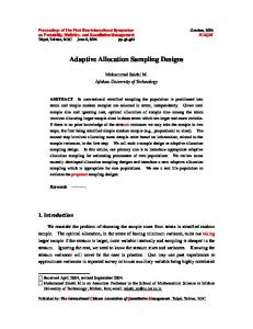
particular set of system parameters and configurations. We will consider the mandatory set only and ignore optional configurations. The benchmark for comparing various modulation formats is the bit error probability [6] measured in terms of the ratio of received bit-energy and noise power density, denoted as γb = Eb /No . However, if we are interested in choosing modes, the received signalto-noise power ratio SNRr is the benchmark. Their relation is: SNRr = γb (Rb /W), where Rb is the bit rate and W is the signal bandwidth. In Fig.2 we illustrate biterror probability (BER) plots in terms of SNRr for b/1 and b/2 modes in L resolvable Rayleigh multipath fading channel with Gray mapping and maximal-ratio diversity combining. For L = ∞, we obtain the non-fading AWGN case.
−2
DBPSK, 1 Mbps
10
DE−QPSK, 2 Mbps −3
10
DE−BPSK, 1 Mbps
−4
10
−5
10
AWGN L=∞
L=2
L=1
−6
10
0
10
20
30
40
50
average received signal−to−noise power : SNRr (dB)
Fig. 2. Bit error probability vs. received SNR of b/1 and b/2 Tx Fig. 1. DATA or fragment delivery over a non-stationary channel
modes in multipath Rayleigh fading channel
Consider an example illustrated in Fig. 1 where the nonstationary channel has two different signal strengths in intervals ∆1 = 0 ≤ t ≤ T1 and ∆2 = T1 ≤ t ≤ T2 . In a unique situation where the initial and final time epochs of the data frame are located in different ∆ intervals Ti ∈ ∆1 and Ti + Tf ∈ ∆2 , two scenarios are possible. If a lower rate mode is selected such that the channel is stable for the entire frame duration, the frame is received error-free but at a sub-optimal transmission rate. On the other hand, if a higher rate mode is selected such that the channel is unstable, the frame is corrupted and must be retransmitted with a reduction in overall throughput. Throughput is maximized if DATA can be transmitted in two different modes. Such mode selection procedure can be achieved by appropriate fragmentation of the data frame. As shown in Fig. 1, each fragment duration Tfrag is carefully chosen to retain channel stability during the duration of each fragment.
For 1 and 2 Mbps modes in 802.11b, the transmit signal is differentially encoded and BSPK/QPSK modulated. The Rx can detect the signal coherently or differentially. If the signal is coherently detected, we denote them as DE-BPSK and DE-QPSK. If differentially detected, they are labelled as D-BPSK and D-QPSK. The BER derivations are omitted due to space limitation but they closely follow results presented in Refs. [5], [6]. Note that our goal is not to measure the performances of various transmission modes. Instead, we wish to show that rate selection based on SNRr is inadequate or inaccurate for optimal performance. This is because we are assuming that the actual BER performance for any mode can be inferred from the static BER plots using measured or estimated SNRr . From the BER plots we see that for a target BER of 10−5 , it is rather difficult to select thresholds SNR∗ (b/1) and SNR∗ (b/2) for 1 and 2 Mbps modes since their values are highly dependent on the type of demodulator/detector, the number of receive antennas, the type of diversity combining and the severity of multipath fading. In contrast, our proposed scheme is insensitive to the Rx architecture since it uses a feedback channel through which the Rx informs its received signal quality to the Tx and the Tx mode is adjusted accordingly.
C. Static Link Budget Analysis When designing a communications system, it is standard practice to prepare a link budget analysis to determine the cost and performance of the entire system for a
1 N=15
N=10
N=5 with RTS/CTS handshake
0.9
N=5
0.8
Throughput (Mbps)
In previous sections we differentiate the loss in throughput resulting from a MAC collision from that due to PHY corruption. We then differentiate the cause of frame corruption: stable versus unstable channel state. We then showed that MAC collision can be eliminated by RTS/CTS handshake. Finally, the stability of the channel can be probed by partitioning a data frame into many smaller fragments. Fragmentation also allows a finer level of channel sensing. Now we are ready to describe how all these functionalities are incorporated into our proposed rate adaptation scheme. RTS/CTS Handshake: With every connection, RTS/CTS is used if DATA duration Tf is above the RTS threshold ∆RTS . (See Sec. IV-A for the optimal value of ∆RTS .) Note that in 802.11 the RTS/CTS handshake is used as a MAC probe. If it is successful, the channel is reserved for the entire duration of the data frame. In RBAR, RTS/CTS is also used as a PHY probe to measure and relay channel and received signal strength. In RBAR, channel probing via RTS/CTS is mandatory regardless of the frame size or data rate. In our proposed scheme, RTS/CTS is used in the conventional sense of channel reservation and hidden node identification. Unlike RBAR, we do not measure channel statistics and SNR based on RTS reception. Therefore the CTS duration/ID field need not be altered. The transmission mode for data delivery is selected a priori based on feedback data over previous CTS and ACK frames. Data Fragmentation: The use of data fragmentation is an option. Based on the history of RSSI values from previous fragment ACKs, we can deduce the channel coherence time. Unlike the RTS/CTS handshake, we use fragments and their corresponding ACKs for the sole purpose of PHY channel probing.
are frame durations of RTS and CTS, respectively and SIFS is the duration of short inter-frame spacing. In deciding when to invoke RTS/CTS, we must compare this overhead loss against the potential gain offered by RTS/CTS by avoiding MAC collisions.
N=10 N=15 N=20
0.7
N=30 N=40 N=50
0.6
0.5 RTS Thresholds 0.4
0.3 0
500
1000
1500
2000
2500
MAC Frame Length (bytes) 8 N = 50
N = 30
N = 20
N=5
7
N = 10
6
N = 20 N = 30 N = 50
Throughput (Mbps)
IV. P ROPOSED R ATE A DAPTATION A LGORITHM
5
4
3
2
RTS Thresholds
with RTS/CTS handshake
1
0 0
500
1000
1500
2000
2500
MAC Frame Length (bytes)
RTS Thresholds for b/1 (top) and b/11 (bottom) modes with long (192 µsec) PLCP preamble and header Fig. 4.
Fig. 3.
Reserved bits in PLCP header of 802.11b
Feedback Channel Support: By utilizing reserved bits in the SERVICE field of the PLCP headers for every type of frame, feedback control information can be exchanged in each transmitter-receiver pair. The PLCP header structure for 802.11 b is shown in Fig. 3. There are 5 reserved bits available in 802.11b to carry feedback data. A. Optimal RTS and Fragment Thresholds We know from Sec. III-A that the inclusion of RTS/CTS handshake eliminates MAC collisions with frames that originate from other STAs within the same BSS as well as from hidden STAs outside the BSS. Its drawback is its overhead equal to TRTS + TCTS + 2SIFS, where TRTS and TCTS
It can be seen from Fig. 4 that the RTS threshold ∆RTS is highly sensitive to the number of contending STAs (denoted by N in the figures) and preamble length. The plots are generated using a modified Bianchi model [3] presented in [4]. (The beaded curves represent throughput plots in basic CSMA mode without RTS/CTS.) In the highest rate b/11 mode with a long preamble, RTS/CTS handshake reduces goodput for any practical frame size since ∆RTS > 1500 bytes for N < 36. However, it can be shown that when a short (96 µs) preamble is used, ∆RTS ≈ 500 bytes and RTS/CTS mechanism should be invoked. We also note that based on similar plots for 802.11a (not shown here), RTS/CTS should be used for N ≥ 15 for all Tx modes (6–54 Mbps). By invoking RTS/CTS we avoid MAC collisions and unnecessary dead time of collided data frames. A similar situation is observed in the PHY layer. If the DATA frame is long, it may be corrupted due to bad channel states or poor rate selection. By invoking fragmentation we
5 4.5
Throughput (Mbps)
4
with arrival rate λ—a parameter equivalent to the channel coherence time Tc . 1.3 1.2 CLARA with fragments
1.1 Throughput (Mbps)
avoid PHY corruption and unnecessary dead time of a corrupted DATA frame. The price for this i improvement is ¡ ¢h the overhead: Nfrag − 1 TACK + 2SIFS ; TACK is the ACK duration and Nfrag is the number of fragments per channel access. Analogous to the RTS/CTS, the fragment threshold is highly sensitive to the channel statistics (in particular, its stationarity) and frame duration. As we will show, we may still want to invoke fragmentation (despite its small loss in goodput) since it improves latency and data flow.
CLARA without fragments
1 0.9
CLARA without fragments
0.8 ARF with fragments
0.7
3.5 ARF without fragments
0.6 3 CLARA with fragments
0.5 0
2.5
20
ARF without fragments
2
40 60 Multipath Fading Simulation Index
80
100
80
100
4.5 1.5 ARF with fragments 1
4
CLARA without fragments
0 5
10 15 20 25 average received signal−to−noise power ratio SNR (dB)
30
5 4.5 4
CLARA with fragments CLARA without fragments
Throughput (Mbps)
0.5
ARF without fragments
3.5
3
Throughput (Mbps)
CLARA with fragments
3.5
2.5
3 ARF with fragments
2.5 2
2 0
ARF with fragments
20
40 60 Multipath Fading Simulation Index
ARF without fragments 1.5
Plot of Throughput for each fading realization; Tc =0.4 ms, SNRr =10 dB (top), Tc =10 ms, SNRr =15 dB (bottom) Fig. 6.
1 0.5 0 5
10 15 20 25 average received signal−to−noise power ratio SNR (dB)
30
Fig. 5. Plot of Throughput vs. received SNRr with data fragmentation; coherence time Tc =2ms (top), 8 ms (bottom)
V. P ERFORMANCE A NALYSIS Using event-driven simulations we study the throughput behavior of our proposed RSA, which we call ClosedLoop, Adaptive Rate Allocation (CLARA). For benchmark comparison, we also provide the performance of ARF. We do not compare CLARA with RBAR since RBAR is a subset of CLARA. In fact, our approach is a practical and improved RBAR since feedback information is piggybacked through both CTS and fragment ACKs. We use the Rayleigh distribution to model the severity of received signal amplitude, quantified in terms p of the Rayleigh parameter σ (i.e. the mean value is π/2 σ and the received signal power is chi-square distributed). The stationarity of the channel is modelled as a Poisson arrival process
The simulation is carried out in MATLAB. Since we are studying the PHY layer behavior, there are only two STAs in the system: Tx and Rx. For each channel access the MAC frame size is 1500 bytes. If fragmented, the maximum number of fragments is 4. The STAs are operating in 802.11 b mode with long PLCP preamble and are capable of communicating in all b modes. In each event 10,000 data frames or 40,000 fragments are exchanged. The Tx selects the best mode based on real-time feedback information. For the transmission of RTS, it uses the mode selected for the frame or last fragment from the most previous channel access. In Fig. 5, the throughput performance of CLARA and ARF with and without fragmentation is shown. Over all SNR range CLARA outperforms ARF; this is expected. For low SNR (5–15 dB), fragmentation is preferred. The gap between CLARA and ARF closes as the channel becomes more stationary (from 2 to 8 ms). The remaining gap is ARF’s inability to adapt received signal fluctuations. For high SNR, fragmentation is not recommended since finer channel sensing is not required and the overhead loss of fragmentation reduces the throughput.
Received SNR
30 20 10
Transmission Mode
Number of retransmission
0 0.25
Number of retransmission
0.35
0.4
0.45
0.3
0.35 Time
0.4
0.45
0.3
0.35
0.4
0.45
0.3
0.35
0.4
0.45
0.3
0.35
0.4
0.45
5 4 3 2 1 0 0.25 5 4 3 2 1 0 0.25
Transmission Mode
0.3
5 4 3 2 1 0 0.25 5 4 3 2 1 0 0.25
Fig. 7.
A time snapshot of rate selection in ARF (top) and CLARA (bottom) in Rayleigh fading
Additionally, when the channel is more stationary there is little performance gain by fragmentation. In order to show the benefits of using fragmentation in non-stationary channels, we run a series of simulations for Tc =0.4 and 10 ms as shown in Fig. 6. We see that with fragmentation, we are able to better sense the channel and as a result, the throughput is not susceptible to deep channel fades and variations, resulting in better QoS in terms of smaller delay and steady data flow. In particular, ARF with its slow rate adaptation leads to choppy data flow and long delays. Note that for low received SNR, CLARA with fragments outperforms its cousin without fragmentation. This trend is reversed for either more stationary or less severe channel condition. Regardless, we see that fragmentation—in both ARF and CLARA—provides a smoother throughput. To demonstrate the efficiency of CLARA —compared to ARF, we compare their respective time snapshots of rate adaptation in Fig.7. Each MAC frame is partitioned into four fragments. The retransmission count starts from 1 for the first attempt. A fragment is dropped after 5 attempts. Transmission modes start from 1 (b/1) to 4 (b/11). Mode 0 denotes a dropped MAC frame. As we can see from the figures, CLARA is able to quickly adapt its mode selection to received SNR variations. VI. C ONCLUSION Our goal is to introduce an intelligent rate selection program that can adaptively select the best mode at any
given time based on measured and estimated system and channel parameters. The outcome is a construction of a virtual duplex channel in 802.11 that supports closedloop rate adaptation via feedback control. The duplex operation is provided by a combination of RTS/CTS control handshake and a sequence of DATA fragments and ACK frames. We have coined such rate adaptation scheme “CLARA” and showed its advantages over other schemes that incorporate non-adaptive blind-mode rate selection procedures. Since rate adaptation is implemented at the PHY layer, it is MAC independent (thus complementary to 802.11e) and therefore can be implemented in all existing and emerging 802.11 WLAN standards. R EFERENCES [1] Gavin Holland, Nitin Vaidya, Paramvir Bahl, “A rate-adaptive MAC protocol for multi-Hop wireless networks,” Proceedings of ACM MobiCom, July 2001, Pages: 236 - 251. [2] Kamerman, Ad; Monteban, Leo, “WaveLAN-II: A highperformance wireless LAN for the unlicensed band” Bell Labs Technical Journal, Summer 1997, Vol. 2 Issue 3, pp. 118. [3] Giuseppe Bianchi, “Performance Anaylsis of the IEEE 802.11 Distributed Coordination Function”, IEEE Journal on Selected Areas in Communications, Vol. 18, Number 3, March 2000. [4] H. Wu, Y. Peng, K. Long, J. Ma, “Performance of Reliable Transport Protocol over IEEE 802.11 Wireless LAN: Analysis and Enhancement”, Proc. of IEEE INFOCOM, vol.2, pp. 599-607, 2002. [5] J. G.Proakis, Digital Communications, 3rd ed., McGraw-Hill, New York, 1995. [6] M. K. Simon and M. Alouini, Digital Communication Over Fading Channels: A Unified Approach to Performance Analysis, John Wiley & Sons, 2000.