symmetry cells, optical functions of one half of the cell are shown in Fig. 1. F1. D1 ... measurement and correction procedures in SIBERIA-2 are described below.
CLOSED ORBIT CORRECTION AND LATTICE PARAMETERS MEASUREMENT AT SIBERIA-2 A.Filipchenko, A.Kalinin, V.Korchuganov, E.Levichev, V.Sajaev, V.Smaliuk, V.Ushakov, BINP, Novosibirsk, Russia A.Kadnikov, Yu.Krylov, V.Ushkov, A.Valentinov, Yu.Yupinov, KSRS, RRC KI, Moscow, Russia 1 INTRODUCTION
2 CLOSED ORBIT
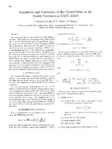
Commissioning of dedicated synchrotron radiation source SIBERIA-2 [1] started in 1995. Now this electron storage ring can operate at nominal energy 2.5 GeV with 7 mA current. Storage ring consists of 6 mirrorsymmetry cells, optical functions of one half of the cell are shown in Fig. 1. F1 20 m
M1
D1
F2
P1
M2
D2 F3
2.1 Orbit measurement For orbit measurement 24 electrostatic pickups with 4 button-like electrodes are used. Horizontal (x) or vertical (z) beam displacements are calculated according to expression:
D3
y = my ⋅
P2
βx βz
10 η x 0
Figure 1. Machine functions of one half of SIBERIA-2 cell. F,D — quadrupole lenses, M — bending magnets, P — pickup stations. As in other dedicated synchrotron radiation sources, lattice of SIBERIA-2 contains strong quadrupole lenses. Small displacements of these quadrupoles cause large distortions of ideal electron orbit. For normal storage ring operation the closed orbit distortions (COD) must be corrected in order to enlarge physical and dynamic apertures and to decrease a distortion of optical functions due to additional focusing in sextupoles. Closed orbit measurement and correction procedures in SIBERIA-2 are described below. Results of the correction are given at injection energy 450 MeV and during energy ramping. After orbit correction the beta- and dispersion functions were measured and their measured values are presented in comparison with ideal lattice ones.
( k1U 1
m k 2 U 2 + k 3 U 3 ± k 4 U 4) ∑k U i
−
y −y 0
G
(1)
i
Here y is x or z, my is a scale factor of the pickup, Ui is the value of the output signal from separate electrode (i = 1,...,4), ki is a levelling coefficient of the electrode (see below), y0 is an electrical zero offset of the pickup and yG is the displacement of the pickup center from the ideal orbit. The scale factors and the electrical zero offsets for the point (x = 0, z = 0) were measured for each pickup with a charged wire and recorded in database. The zero offset measurement accuracy is 0.1 mm. The signals Ui are proportional to a charge induced on electrode by the beam and inversely proportional to a total capacitance of electrode circuit. Difference between these capacitances causes a zero offset which is eliminated by means of the levelling coefficients. To determine them, a calibration procedure is used. Ui are produced by the same calibration current and the levelling coefficients are calculated and recorded into database. Calibration procedure provides reproducibility of signals corresponding to the accuracy of 0.01 mm.
2.2 Steering magnets Orbit distortions can be reduced by means of dipole fields of additional windings in quadrupoles and bending magnets. Lattice of SIBERIA-2 contains 50 horizontal and 46 vertical such correctors. Focusing lenses (besides of F2, see Fig.1) have horizontal dipole correcting coils and defocusing lenses have vertical ones. Bending magnets also have additional horizontal correctors [1].
Parameters of correctors at 450 MeV are given in Table 1. Table 1. Parameters of dipole correctors at 450 MeV. Correcting coil Effective Max. deflection position length, cm angle, mrad Quadrupoles F3 40 4.2 Other quadrupoles 30 3.1 Bending magnets 17.5 4.9 The field generated by dipole corrector in quadrupole lens depends on transverse coordinate x according to expression: −7
⋅ B z ( x ) = 8 π 102 Iw R0
⋅
x
(1 − exp ( - π x2 R0
1
2
)
(2) 2
)
where R0 is the bore radius and Iw are Ampere-turns. Expression (2) shows the existence of sextupole component in the correcting field: ∂ Bz π Bz = = 2000 2 2 ∂ x 2 R0 2
Bz
• #TROY provides local correction by triple of correctors at selected pickup position. In many options #TROY is similar to #MINI. Third group of codes provides a simulation of the correction process. It is a part of large number of DAcodes (Design of Accelerators) developed in BINP for accelerators’ modelling. They operate with magnetic lattices’ files in special DA-format: • #GETS gets the currents of power supplies from SIBERIA-2 control system and creates a file with lattice in DA-format according to results of magnetic measurements; • #DATC calculates the response matrix for SIBERIA2 lattice using the file created by #GETS; • #DACC calculates closed orbit in the presence of given correctors or field errors; • #DAHA rebuilds whole closed orbit from pickups’ signals using harmonic technique and the lattice created by #GETS. Other DA-codes can calculate optical functions, radiation integrals, provide particle tracking, dynamic aperture calculations and many useful tools for accelerator design.
(3)
2.3 Software For orbit correction goals set of computer codes was designed. All software can be divided into three groups. First group of codes works with pickup stations: • #PICK provides pickup calibration and saves the results in database; • #ORBI measures orbit with periodicity of 5 seconds; • #GORB displays orbit on color graphic monitor, keeps it in special file and sends it to central computer, so all other codes can use it. Second group of codes provides several correction techniques: • #RESP measures a response matrix of the lattice. It can set additional current to selected corrector and write resulting orbit displacement to a special file. This code also allows to exclude from operation pickups or correctors selectively; • #MINI operates with several linear methods of global orbit correction. All of them use measured or calculated response matrix. These are least square roots methods (LSQ) [2] and MICADO [3]. One have to choose a direction (x or z), number of correctors involved and number of iterations. Then code proposes for choice several possible ways of correction. One can choose appropriate correction variant. The code permits to cancel last correction. It can use real-time measured orbit or any saved one. There is a possibility to introduce non-zero reference orbit;
2.4 Correction results At first stage of commissioning COD reached 7 mm for x-direction and 5 mm for z-direction at pickup azimuths. Calculated response matrix and LSQ method with small number of correctors were used for correction. Final correction scheme involves only 4 z-correctors and 8 xcorrectors with maximum strength 0.5 mrad. It shows that real magnetic structure of SIBERIA-2 corresponds well to ideal one. Z-correction has allowed to increase the injected current. Closed orbit after correction at 450 MeV is shown on Fig. 3.
Figure 3. Screen of color monitor where vertical (top) and horizontal orbit displacements are displayed.
Orbit parameters after correction are given in Table 2. Table 2. Orbit parameters after correction. Direction Mean COD, RMS COD, Maximum mm mm COD, mm X -0.36 1.0 1.9 Z 0.20 0.8 1.5 The currents in correctors grow proportionally to energy during energy ramping. Above 2 GeV an iron saturation in magnetic element yokes causes displacement of closed orbit, so additional correction was made. Resulting maximum orbit deviations are approximately the same as at injection energy. Special hysteresis cycle was organized for main magnetic elements in order to stabilize working point and closed orbit at injection energy.
3 LATTICE FUNCTIONS Lattice function measurements were produced after COD correction. Dispersion function at pickup azimuth is proportional to the orbit displacement when frequency of RF system is slightly changed. Calculated and measured vertical and horizontal dispersion functions are given in Table 3. The accuracy of measurement is 0.02 m. Table 2. Dispersion functions ηx and ηz of SIBERIA-2 at 450 MeV. See Fig. 1 for pickup position. Pickup Ideal Measured Ideal Measured position ηx , m ηx , m ηz , m ηz , m P1 0.53 0.55 ± 0.1 0 0 ± 0.05 P2 0 the same -0.04±0.06 0 We think the spread of measured x-dispersion function is explained by its modulation with periodicity of one half of the ring circumference. This modulation is caused by the errors in field gradient at the azimuths of two ‘triplets’ of quadrupoles situated in first and fourth cells. Vacuum chambers of these triplets are intended for extraction of power photon beams from superconducting wigglers and made from slightly magnetic stainless steel whereas main part of vacuum chamber is made from aluminium alloy. β-functions were measured by two ways. First way is to change current in every quadrupole family and to find betatron tune shifts. One can calculate mean value of β-
functions over quadrupoles of one family using expression: 4 π ⋅ B ρ ⋅ ∆Q β = (4) ∆G ⋅ N ⋅ l where ∆G is a field gradient change and l is an effective length of given quadrupole, ∆Q is betatron tune shift, Bρ is magnetic rigidity and N = 12 is number of quadrupoles in the family. Tunes are determined with accuracy 0.001 by resonance excitation of the beam. Results of measurements are presented in Table 4. An accuracy of measurements is near 10%. It was found that all measured values are less than ideal ones because of a nonlinear dependence of betatron tunes on quadrupoles’ gradients. Working point is too close to difference resonanse and relatively strong coupling was observed (initial betatron tunes are Qx = 7.77, Qz = 6.70 and minimum possible difference between them is 0.025). Table 4. β-functions in quadrupole lenses at 450 MeV. Lens Ideal Measured Ideal βx , m βx , m βz , m F1 11.5 9.4 7.3 D1 4.4 3.3 14.3 F2 1.5 1.3 1.3 D2 4.3 3.6 7.0 F3 13.6 11.6 3.2 D3 5.1 4.9 4.7
of SIBERIA-2 Measured βz , m 6.1 12.2 1.2 6.3 2.5 4.5
Another way is to use special gradient correction coils with maximum strength 0.4 T/m in every quadrupole. They are designed for compensation of betatron tune shifts in the presence of insertion devices. In this case N = 1 in expression (4). Observed 15-20% modulation of β-functions is caused by the same reason like the modulation of dispersion function.
4 REFERENCES [1] “Magnetic lattice of SIBERIA-2 -- dedicated SR source”. G.Erg, N.Gavrilov, V.Korchuganov et al. Preprint BINP 89-174, Novosibirsk. [2] “Correction of closed orbit at injection in alternatinggradient synchrotron”. A.Ando, K.Endo. KEK-75-4, 1975. [3] “Closed orbit correction of A.G. Machines using small number of magnets”. B.Autin, Y.Marty. CERN-ISR-MA/73-17, Geneva, 1973.