Nov 4, 1997 - purpose architectures are not capable of meeting domain speci c constraints. In the case of portable .... solution for that is the use of register-register instructions. This is the case of .... R3 have been recently modi ed by load operations. Register R1, on ..... 8th International Symposium on System. Synthesis ...
O conte�udo do presente relat�orio �e de u�nica responsabilidade do(s) autor(es). The contents of this report are the sole responsibility of the author(s).
Code Generation for Dual-Load-Execute Architectures Guido Araujo and Sharad Malik
Relat�orio T�ecnico IC{97-21
Novembro de 1997
Code Generation for Dual-Load-Execute Architectures Guido Araujo and Sharad Malik November 4, 1997
Abstract This paper studies the problem of register allocation and scheduling for Dual-LoadExecute (DLE) architectures. These are architectures which can execute an ALU instruction and two memory transfer operations (load/store) in a single instruction cycle. DLE architectures are extensively used in the design of Digital Signal Processors (DSPs) like the Motorola 56000, Analog Devices ADSP-2100, and NEC �PD77016. This work proves the existence of an e�cient O(n) expression tree code generation algorithm for DLE architectures which have homogeneous register sets. The algorithm is an extension of the Sethi-Ullman algorithm, and produces guaranteed optimal code for a large number of expression trees in the program. The experimental results, using the NEC �PD77016 as the target processor, show the e�cacy of the approach.
1 Introduction Digital Signal Processors (DSPs) are receiving increased attention recently due to their role in the design of modern embedded systems like video cards, cellular telephones and other multimedia and communication devices. DSPs are largely used in systems where generalpurpose architectures are not capable of meeting domain speci c constraints. In the case of portable devices, for example, the power consumption and cost may make the usage of general-purpose processors prohibitive. Unfortunately, code generation for DSPs is a much harder problem then generating code for general-purpose processors. This research is part of a project directed towards developing compilation techniques that are capable of producing quality code for such processors. The implementation of these techniques forms the compiling infrastructure used in this work. There is a large body of work done in code generation for general-purpose processors. Code generation is, in general, a hard problem. Instruction selection for expressions subsumes Directed Acyclic Graph (DAG) covering, which is an NP-complete problem [1]. Sethi et al. [2, 3] showed that the problem of optimal code generation for DAGs is NP-complete even for a single register machine. It remains NP-complete for expressions in which no shared term is a subexpression of any other shared term [4]. Code generation for expression trees has a number of O(n) solutions, where n is the number of nodes in the tree. These algorithms o�er solutions for the case of stack machines [5], register machines [6, 7, 8] and machines with specialized instructions [9]. They form the basis of code generation for single issue, in order execution, general-purpose architectures. The problem of generating code for DSPs and embedded processors has not received much attention though. This was probably due to the small size of the programs running on these architectures, which enabled assembly programming. With the increasing complexity of embedded systems, programming such systems without the support of high-level languages has become impractical. Many of the problems associated with code generation for DSPs were rst brought to light by Lee in [10, 11], a comprehensive analysis of the architectural features of these processors. Code generation for DSP processors has been studied in the past, but only more recently a number of interesting projects have tackled some of 2
its important problems. Marwedel et al. [12] proposed a tree-based mapping technique for compiling algorithms into microcode architectures. Paulin et al. [13] uses a tree-based approach for algorithm matching and instruction selection, where registers are organized in classes and register allocation is based on a left- rst algorithm. Datapath routing techniques have also been proposed [14] to perform e�cient register allocation. Wess [15] proposed the usage of Normal Form Schedule for DSP architectures, and o�ered a combined approach for register allocation and instruction selection using the concept of trellis diagrams [16]. An overview of the current research work on code generation for DSP processors, and embedded processors in general, can be found in [17]. The high performance requirement of DSP applications lead designers to make extensive use of parallelism in the design of DSP datapaths. A very common technique, employed in a number of processors [18, 19, 20], is to fetch the operands of the next instruction during the execution of the current one. The idea here is to hide the latency of the memory access by transferring the data from/to memory during the time when an instruction performs a computation. The immediate consequence of that is an increase in the memory bandwidth requirement. In order to meet this requirement, DSPs use memory banks, which can be accessed in parallel. Although multi-ported memories1 are another way to achieve the required bandwidth, they are usually not considered a design option because of their large silicon area requirements. When memory banks are used, a dual-bank organization is preferred, given that the majority of the instructions in a DSP application are binary instructions. This architectural style allows the design of processors which can perform an ALU operation together with two load (store) transfer operations from (into) memory. Because of this feature these processors will be referred to as Dual-Load-Execute (DLE) architectures in the sequel. This paper proposes an optimal O(n) code generation algorithm for expression trees for a class of DLE architectures which have homogeneous register sets. The NEC �PD77016 processor is a typical architecture of this class, and will be considered the target machine during this work. This paper is divided as follows. Sec. 2 describes the architectural model used to 1 A multi-ported memory is a memory which allows more than one load/store operation to occur at the same time.
3
represent the processor datapath. Sec. 3 gives an instance of the problem and discusses its formulation. Sec. 4 states the basic concepts required for the rest of the paper. Sec. 5 proposes an algorithm for the expression tree code generation problem. Finally, Sec. 7 describes the experiments designed to show the e�cacy of the algorithm.
2 Architectural Model A key aspect in the design of a DSP architecture is how instructions in the processor Instruction Set Architecture (ISA) make use of its datapath structures. A careful analysis of the various types of DSP datapaths reveals a large variation of styles. The Register Transfer Graph (RTG) model of a processor seeks to address this variety [21]. The RTG representation of a processor exposes the storage locations in the processor datapath, and captures how the instructions in the processor ISA use the transfer paths de ned between these locations to perform the required computation. The RTG is a directed labeled graph where each node ni represents a register class in the processor and the edges are transfer paths de ned by the ISA. Each edge (n1 ; n2) in the RTG is labeled with those instructions in the ISA which take operands from register class n1 and store the result into register class n2. The nodes in the RTG represent two types of storage: single-register and multipleregister. Multiple-register nodes are associated with a register class that can store multiple operands. A single-register node (or simply register) is a register class of unitary capacity. In the RTG, multiple-register nodes are distinguished from single-register nodes by means of a double circle. Memory is assumed to be an in nitely large storage resource, and is not represented in the RTG for simplicity. An arrowhead is used to indicate when a transfer path exist between an RTG node and memory. The direction of the arrow shows the direction of the transfer operation. An incoming (outgoing) arrow is associated with a load (store) operation. Datapaths of three commercial DSPs have been modeled using the RTG representation. Table 1 (a - c) shows the datapath of the processor together with its RTG representation and a typical instruction. For the sake of simplicity, the instructions of the three processors are described using the same syntax. In this syntax, a bar is present between two operations that execute during the same instruction cycle. The TMS320C25 processor is shown in 4
Table 1(a). The fact that one operand is stored in memory is a major drawback in the performance of this processor. In this processor, the latency of any instruction is the sum of the memory access time plus the latency of the functional unit. This has a signi cant impact on the cycle time of the processor, given that memory latency has become increasingly large. The impact is reduced because memory in DSPs are static on-chip RAMs, which have faster access times when compared with their dynamic versions. Unfortunately this is not enough to compensate for the increasing gap between memory and register access times. The solution for that is the use of register-register instructions. This is the case of the NEC �PD77016 processor in Table 1(b). The �PD77016 has a single register le and can perform two accesses to memory together with an ALU operation. Therefore, the NEC �PD77016 is a DLE architecture. The NEC �PD77016 has one multi-ported register le (R) and a memory system based on two memory banks, MX and MY. This combination allows for three accesses to registers in R to occur in a single machine cycle (e.g. MAC instruction). A typical binary instruction in this architecture reads two registers R1 and R2, and stores the resulting computation into R3. After that registers R4 and R5 load the operands for the next instruction from banks MX and MY. The main drawback of this architecture is the use of a multi-ported register le. Multi-ported register les are expensive in terms of silicon area and design e�ort, both of which impact the nal cost of the device. Observe that instructions from this processor do not restrict the registers they use, hence the register set is homogeneous, and we say that the NEC �PD77016 is a homogeneous DLE architecture. Another variation of a DLE design is shown in Table 1(c). The idea now is to eliminate the costly multi-ported register le, while maintaining the Dual-Load-Execute property. In this case two registers les (RX and RY) are used to perform the dual-load operation. The result of an instruction is always stored in the accumulator register le A. A typical instruction in this architecture performs its operation using a register from A and the current contents of a register from RX and/or RY. After that registers in RX and RY can be loaded with the operands for the next instruction. Since registers in RX and RY are separated from A, no multi-ported register le is required, which results in a reduction of the total silicon area used by the processor. This was the approach adopted in the design of the Motorola 56000 processor [18]. 5
(a) MEM
MEM BUS t
MUL SHIFTER1
p
p
a
SHIFTER2
t
MUX
ALU
a
SHIFTER3
ADD M1
MEM BUS
(b) MX
MY
R
R
MAC
BARREL SHIFTER
ALU
ADD R1; R2; R3 LD R4; MX0 LD R5; MY0 j
j
(c) MX
MY
MUX
MUX
RX
RY
MUL p
RX
A
MUX
ALU
RY
A
ADD A0 ; RX1 LD RX0 ; MX0 LD RY0 ; MY0 j
j
6 Table 1: Architectural model and typical instructions for three commercial DSPs: (a) TI TMS320C50; (b) NEC �PD77016; (c) Motorola 56000.
The trade-o� between architecture and code generation algorithms for DSPs becomes clear when one analyzes the algorithms required to generate code for each architecture in Table 1. A cycle in the RTG is a path starting and nishing at some node ni , which traverses at least another distinct RTG node. Hence a self-loop is not an RTG cycle. It has been shown [21] that an optimal O(n) expression tree code generation algorithm exists for acyclic RTGs like the one described in Table 1(a). Unfortunately the problem for cyclic RTG architectures, like the one in Table 1(c), seems to be NP-hard. Observe that the DLE architecture of Table 1(b) has no RTG cycles, hence it must admit an e�cient algorithm. The goal of this paper is to nd this algorithm.
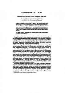
3 Problem Formulation Consider a homogeneous DLE architecture like the one described in Table 1(b). Fig. 1(b) shows the best code generated for the expression tree T of Fig. 1(a) on this architecture. The code in Fig. 1(b) uses memory positions m1 ? m6 as operands to evaluate T . The result of the expression is stored into m7. As mentioned before DLE instructions are formed by 11
| LD R1, m1 | LD R2, m2 7
10
3
6
m1
m2
m3
m4
1
2
4
5
m5
m6
8
9
(a)
I
1
MUL R1, R1, R2 | LD R2, m3 | LD R3, m4
I2
ADD R2, R2, R3 |
I3
|
SUB R1, R1, R2 | LD R2, m5 | LD R3, m6
I4
MUL R2, R2, R3 |
|
I5
ADD R1, R2, R2 |
|
I6
| ST R1, m7 |
I7
(b)
Figure 1: (a) Expression tree T storing into m7 ; (b) DLE code corresponding to T ; compacting an ALU operation, and two load/store operations into a single instruction. In order to improve register utilization, it is desirable that the same registers which are used as operands by the current ALU operation could also load the operands of the next ALU operation, after the former is nished. To achieve this goal, DLE architectures are designed 7
such that registers are read in the beginning of the instruction cycle and written at the end of the cycle. This allows a register to provide an operand to the ALU at the beginning of the cycle, and be updated at the end of the same cycle. It also allows a result register to be stored into memory at the beginning of the cycle, and be updated with a new result at the end of the same instruction cycle. For example, instruction I2 of Fig. 1(b) loads registers R2 and R3 (operands of I3) only after the multiplication in I2 is performed. On the other hand, the store operation required to move R1 into m7 (instruction I7 ) cannot execute during instruction I6, since the new value of R1 is only available at the end of I6 . In this case, a separate instruction is required (I7), to hold the store operation. Had the store operation been compacted into I6 the value stored into m7 would be the old value of register R1. The problem this paper addresses is: Given an expression tree T (e.g. Fig. 1(a)) determine the code that computes T in the minimum number of cycles and using the least number of registers. Notice that a DLE architecture enables any program for an expression tree to execute in p + 2 cycles, where p is the number of ALU operations in T 2. This is possible because all load operations for the operands of an ALU instruction, but the rst one, can be compacted into some previous ALU instruction. Furthermore, this is a consequence of the fact that a DLE instruction enables two operands to be loaded at the same time, and that the expression trees are binary. In addition to p cycles, one extra instruction cycle is required to load the operands of the rst instruction. In the case of Fig. 1(b), for example, I1 loads the operands for I2 . Yet another cycle is needed to store the result of the operation at the root of the tree. Instruction I7 in Fig. 1 is used for that. Observe that the optimal code from Fig. 1(b) can only be achieved i� the number of registers required by the expression tree is minimized. If care is not taken to minimize the number of registers, then the resulting program could require a memory spill, increasing its execution time. Memory spill is the situation when there are not enough registers to execute some operation in T . As a consequence two memory operations have to be issued. A store operation, to save the contents of a register, and a load operation to reload this register later. Meanwhile, the vacant register can be used as the destination of the current 2
Assume, without loss of generality, that each instruction takes one machine cycle
8
operation. For the sake of simplicity assume that no Global Register Allocation (GRA) is performed. This assumption is not restrictive, since the goal here is to generate code for basic blocks, and thus to minimize the number of registers allocated for temporaries. When GRA is used the problem is exactly the same, with a smaller number of registers available for temporaries. This is similar to the situation found when GRA is performed during code generation for general-purpose processors [22].
4 The Basics Before proceeding further we need to de ne concepts and terms that will be used throughout this paper.
4.1 The Sethi-Ullman Algorithm Let T be a binary expression tree in a homogeneous general-purpose architecture. Optimal code for T can be generated in O(n) by means of the Sethi-Ullman algorithm [6]. The ideas proposed by this paper are built upon this algorithm. The Sethi-Ullman algorithm is based on a labeling procedure which assigns a label to each node u in T . This label is known as the Sethi-Ullman Number of the node, or SUN (u), and corresponds to the minimum number of registers required to evaluate the subtree rooted at u. The SUN (u) can be computed recursively using a bottom-up post-order traversal of the tree rooted in u. At each node u with children u1 (root of subtree T1 ) and u2 (root of subtree T2) compute:
8 >< max(SUN (u1); SUN (u2)) if SUN (u1) 6= SUN (u2); SUN (u) = > : SUN (u1) + 1 if SUN (u1) = SUN (u2):
(Eq:1) (Eq:2)
The labeling procedure minimizes the number of registers required to compute the subtree rooted in u. This is done by giving priority to schedule rst the subtree of u which uses more registers. There are two cases to consider here. The rst case (Eq. 1) occurs when one of the subtrees (e.g. T1) uses more registers than the other (e.g. T2). In this case, T1 should be scheduled rst followed by T2 . SUN (u1) registers are used during the scheduling of T1. After T1 is scheduled, only one register is live to hold the result of operation u1 . 9
Therefore, during the scheduling of T2 at most SUN (u2)+1 � SUN (u1) registers are used. Hence, the minimum number of registers required to schedule the tree at u is the maximum number of registers used by its subtrees. Now consider the case (Eq. 2) when the same number of registers is needed by T1 and T2. In this case, no matter the subtree scheduled rst, the total number of registers required is one plus the number of registers used by the subtrees. The Sethi-Ullman algorithm evaluates an expression tree contiguously, i.e. the operations in subtree T1 (T2) are scheduled only after all operations in subtree T2 (T1) have been scheduled. Because of that we say that the Sethi-Ullman algorithm satis es the Contiguous Evaluation Property [6].
4.2 Basic De nitions De nition 1 Let T be a binary expression tree and P a program that evaluates T . Register R is said to be a load-register, at some point of the execution of P , i� the last operation to modify R was a load operation.
Example 1 Consider, for example, the expression tree of Fig. 1(a) and its corresponding
code in Fig. 1(b). Notice that during the execution of instruction I3 only registers R2 and R3 have been recently modi ed by load operations. Register R1 , on the other hand, was last updated by the MUL operation. Therefore only R2 and R3 can be considered load-registers at that point of the program execution. Without loss of generality, assume that operations and nodes in T form a one-to-one relation, i.e. there exist a function op which maps a node ui 2 T into its corresponding operation oi , i.e. oi = op(ui ). Operation oi is an ALU operation or a load/store operation.
De nition 2 A DLE instruction generated from an expression tree T , is a tuple I =
(o1; o2; o3), where o1 is an ALU operation, o2 and o3 are load/store operations, or oi = � (empty), i = 1; 2; 3. An empty operation is an operation which performs no task. An empty operation oi is used to represent those cases where no operation can be compacted into eld i of I .
De nition 3 A partial DLE instruction I is a DLE instruction for which at least one of 0
the operations oi ; i = 1; 2; 3 have not been de ned yet. In this case the underline symbol
10
(" ") is used in the unde ned eld i of I . 0
Partial DLE instructions are uncompacted DLE instructions. For example I2 = ('MUL R1, R2, R3', , ) is the partial version of instruction I2 in Fig. 1(b), for which the load operations 'LD R2, m3' and 'LD R3, m4' have not been compacted yet. We say that a (partial) DLE instruction is an ALU instruction if it contains an ALU operation, and a load/store instruction otherwise. 0
5 Problem Solution The goal of this section is to show that given an expression tree, in an homogeneous DLE architecture, it is possible to generate optimal code for it in O(n), where n is the number of nodes in T .
Lemma 1 Let T be a binary expression tree, and P the program which evaluates T obtained
after applying the Sethi-Ullman algorithm to schedule T . At most two load-registers are live at any time during the execution of P .
Proof. Let h be the height of expression tree T . Let T1 (T2) be a subtree of T , and
h1 (h2) its corresponding height. Assume, for the sake of clarity, that T1 (T2) is the left (right) subtree of T , rooted at u1 (u2 ). Let R(ui ) = ri be a function which maps node ui 2 T to the register used to store the result of op(ui ). Let l1 , l2 and l be the number of simultaneously live load-registers respectively used during the computation of T1, T2 and T . We want to show that l � 2 for any expression tree T , provided that code is scheduled using the Sethi-Ullman algorithm. Basis. First, let us prove that l � 2 is true for 0 � h � 1. In this situation two cases have to be considered, corresponding to trees of height zero and one. (a) A tree T of height zero corresponds to a single leaf node, which is mapped to a load operation. Hence l = 1 � 2. (a) Consider a binary tree T which is a single binary operation. In this case at most two load-registers R(u1) = r1 and R(u2 ) = r2 can be live at the same time. Hence 11
l = 2 � 2. If the tree is formed by an unary operation then only one load-register is used and therefore l = 1 � 2. u3
u3
u3
u1
u2
u1
T1
T2
T1
u2
u2
T2
(b)
(a)
u1
(c)
Figure 2: (a) h1 = h ? 1 and/or h2 = h ? 1; h1 > 0; h2 > 0; (b) h1 = 0 and h2 = h ? 1; (c) h1 = h ? 1 and h2 = 0.
Induction. Let SUN (ui) be the Sethi-Ullman Number of node ui. By de nition [6]
SUN (ui) is the number of registers required to compute the subtree rooted at ui . Consider T1 and T2 to be subtrees of T and h1 (h2 ) the height of T1 (T2). Let the basis argument be true for all trees with height h ? 1. It is to be shown that this is also true for all trees of height h. Consider now three cases:
(a) This is the case when h1 = h ? 1 and/or h2 = h ? 1, and h1 > 0; h2 > 0. From the induction hypothesis we know that l1 � 2 and l2 � 2. Therefore, at most two load-registers become live at the same time during the execution of the instructions in T1 or T2. The Contiguous Evaluation Property of the Sethi-Ullman algorithm [6] guarantees that operations in subtree T1 (T2) (Fig. 2(a)) are only scheduled after all operations in subtree T2 (T1). Given that u1 (u2) is not a leaf node, then after instructions in T1 (T2) are nished, no load-register is live. Therefore at most two load-registers will be used during the computation of T , and thus l � 2. (b) In this case (Fig. 2(b)) h1 = h ? 1 and h2 = 0 (i.e. subtree T2 is composed of a single leaf node). As before, T1 uses at most two simultaneously live load-registers (l1 � 2) and SUN (u1) � 1. On the other hand T2 uses just one register, i.e. SUN (u2) = 1 and l2 = 1. Hence SUN (u1) � SUN (u2), and according to the Sethi-Ullman algorithm [6] subtree T1 is scheduled rst followed by T2 . Given that l1 � 2 and no load-register is live after all operations in T1 are completed, then l = l1 � 2. 12
(c) This case (Fig. 2(c)) is the symmetric of case (b). Since SUN (u2) � SUN (u1), then T2 is scheduled before T1 [6] . Similarly as before, no load-register is live after the operations in T2 are executed. Given that l2 � 2, then l = l2 � 2.
2
Corollary 1 Program P , as de ned in Lemma 1, has no more than two load instructions 0
in between a pair of consecutive ALU instructions Ii and Ij . Moreover each load instruction is used to load an operand of Ij . 0
0
0
Proof. Assume that the rst assertion is not true. Let Ii and Ij be a pair of consecutive 0
0
ALU instructions such that there exist more than two load instructions in between them. In this case more than two load-registers are live at the same time in P , what is a contradiction of Lemma 1. Now assume that there exist an instruction Ik , which follows Ij in P , such that one of the load instructions in between Ii and Ij loads an operand for it. This is only possible if the Sethi-Ullman algorithm generates code rst for a leaf-node u (i.e. load instruction), and then generates code for an inner-node (i.e. ALU instruction), which is not the parent of u. Given that the Sethi-Ullman algorithm satis es the Contiguous Evaluation Property (Sec. 4.1), then this is only possible in cases (b) or (c) of Lemma 1. But in case (b) ((c)) code is generated rst for the inner-node u1 (u2 ) and then for the leaf-node u2 2 (u1). Therefore no such instruction Ik exist. Now consider the following algorithm to generate code for an expression tree T . This algorithm is an extension of the Sethi-Ullman algorithm [6] for the case of homogeneous DLE architectures. 0
0
0
0
0
0
0
Algorithm 1 [Sethi-Ullman DLE]
Let T be an expression tree containing n nodes. The optimal program P which evaluates T in a homogeneous DLE architecture can be determined as follows: 1) Use the Sethi-Ullman algorithm to generate the optimal sequential program P = I1; I2; : : :; In which evaluates T . Each instruction Ii ; 1 � i � n is a partial DLE instruction, which contains a single operation oi = op(ui ); ui 2 T . 0
0
0
0
0
13
2) Let If be the rst ALU instruction scheduled in program P . Consider now two cases. First, consider the set of all ALU instructions in P but If , i.e. the set fIj ; j 6= f g. Compact the load instructions between Ij and ALU instruction Ii into Ii , where i = max(k); f � k � j ? 1. In other words, compact the load instructions for the operands of Ij into the rst ALU instruction Ii that can be found by traversing P backwards from Ij to If . Finally, compact the load operations for the operands of If into I1. 0
0
0
0
0
0
0
0
0
0
0
0
0
0
LD R1, m1
I'1
LD R2, m2
I'2
MUL R1, R1, R2
I'3
LD R2, m3
I'4
LD R3, m4
I'5
ADD R2, R2, R3
I'6
SUB R1, R1, R2
I'7
MUL R1, R1, R2 | LD R2, m3 | LD R3, m4
I2
LD R2, m5
I'8
ADD R2, R2, R3 |
I3
LD R3, m6
I'9
SUB R1, R1, R2 | LD R2, m5 | LD R3, m6
I4
MUL R2, R2, R3
I'10
MUL R2, R2, R3 |
|
I5
ADD R1, R2, R2
I'11
ADD R1, R2, R2 |
|
I6
ST R1, m7
I'12
| ST R1, m7 |
I7
| LD R1, m1 | LD R2, m2
I
|
(a)
1
(b)
Figure 3: (a) Code after step 1 of SU-DLE; (b) Code after step 2 of SU-DLE.
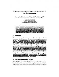
Example 2 Consider, for example, applying the Sethi-Ullman DLE (SU-DLE) algorithm
to the expression tree in Fig. 1(a). The code resulting after the execution of step 1 is shown in Fig. 3(a). Notice that there exist at most two load instructions in between two consecutive ALU instructions and that these instructions load the operands for the following ALU instruction. For example, instructions I4 and I5 load the operands for instruction I6 . The rst ALU instruction in the program is I3 (i.e. If = I3). All load instructions from I4 to I12 are compacted into some ALU instruction (I3 and I7 ), and the load instructions for I3 (i.e. I1 and I2) are compacted into I1 . Fig. 3(b) shows the resulting code after the compaction step 2 is performed. The compacted load operations are highlighted is boxes. The nal code executes in 7 (i.e. p + 2) steps, and uses 3 registers. 0
0
0
0
0
0
0
0
0
0
0
0
14
0
Remark 1 For the sake of simplicity we have assumed that the architecture can reutilize a
source register as the destination register for the operation result. This might not always be true for some architecture. In this case, it is enough to modify the Sethi-Ullman algorithm such as to increase by one the number of registers required at each subtree.
Theorem 1 Algorithm SU-DLE generates an optimal program which evaluates T using the
least number of registers.
Proof. From step 1 of the SU-DLE algorithm P is the optimal sequential program 0
which evaluates T . If each ALU operation executes in one cycle, then P takes n cycles to execute and uses SUN (root(T )) registers, where root(T ) is the root node of T . Now consider step 2 of the SU-DLE algorithm. Two situations have to be analyzed here. First, consider the case of ALU instructions Ij ; j 6= f . If the ALU operation in Ij is an unary (binary) operation then the instructions that load its operand(s) can always be compacted into some previous ALU instruction Ii . The existence of Ii is guaranteed from Corollary 1, since at most two load instructions can exist between instructions Ii and Ij , and these are the instructions that load the operands of Ij . Therefore all load instructions in P from instruction If to instruction In can be compacted into some ALU instruction by traversing P bottom-up. The just compacted sequence of ALU instructions has length p, where p is the number of non-leaf nodes (i.e. ALU operations) inside T . Now consider the case of instruction If . The operands of If can be loaded simultaneously in the beginning of P , but cannot be compacted into another ALU instruction. Hence one cycle is needed to load the operands of If . Assume above that the allocation of memory variables to the memory banks is such that it permits the parallel access of the compacted load operations. Now observe that instruction In uses one cycle to store the result of the operation in root(T ) into memory. Therefore, the nal program which evaluates T is a sequence of DLE instructions P = I1; I2; : : :Ip+1 ; Ip+2 of length p + 2. Assuming that each ALU operation takes one cycle to execute, then P execution time is p + 2 cycles. As discussed before, this is the minimum number of cycles required by any program to evaluate T in an homogeneous DLE architecture. The compaction of the load operations does not change the liveness of the registers in P . Between two ALU instructions Ii and Ij in the uncompacted program P 0
0
0
0
0
0
0
0
0
0
0
0
0
0
0
0
0
0
0
15
0
0
there are two live load-registers which load the operands of Ij . The compaction step does not change the liveness of these or other registers. Therefore, the minimum number of registers needed to evaluate T , using the compacted code P , is the same as the minimum number of registers needed by the uncompacted code P , i.e SUN (root(T )) registers. 2 0
0
Theorem 2 Algorithm SU-DLE is O(n), where n is the number of nodes in T . Proof. It takes O(n) steps to schedule operations ui from T using the Sethi-Ullman
algorithm. It takes at most two steps to compact two load operations for each one of the p; p < n, ALU instructions of P . Thus the execution time of SU-DLE can be bounded by O(n) + 2 � O(p) = O(n). 2 un+1
un+1
un
un
u5
u5
T
T
n
n
u3
u3
u4
T
T
u1
u2
3
m1
u2
3
T
T T
u4
2
2
1
(a)
(b)
Figure 4: (a) Expression tree T1 uses more registers than available; (b) The result of operation u1 is restored from memory position m1.
6 Dealing with Spilling This section studies the situation when a memory spill is required during the evaluation of T . Let jRj be the number of registers available in the architecture and T an expression S tree. Assume that the evaluation of subtree T3 = T1 T2 from Fig. 4(a) needs more than the number of registers available in the architecture, i.e. SUN (u3) > jRj. According to the Sethi-Ullman algorithm this can only occur when SUN (u1) = SUN (u2) = jRj. In this case, code is rst generated for one of the subtrees of T3. Let T1 be the chosen subtree. The 16
result of the operation at u1 is stored into some memory position, e.g. m1 , and sub-tree T1 is substituted by a leaf-node m1 . Code is then generated for the remaining subtree shown in Fig. 4(b). In general subtrees of T rooted in u, for which SUN (u) = jRj, are scheduled rst, followed by the schedule of the remaining operations of T . Let P1 (Pk ) be the program which evaluates T1 (Tk ), such that Pk is scheduled just after P1 in program order. Fig. 5 shows this situation. We want to study the possibility of compacting instructions from P1 and Pk , such as to minimize the overhead due to the uncompacted load (store) instructions at the beginning (end) of these programs. This problem occurs not only when T1 and Tk are subtrees of the same tree, as in the case of spilling, but also when they are unrelated trees which have been scheduled consecutively during the generation of code for a basic block. Notice that one can always compact the load operation(s) from the rst instruction of Pk , i.e. I3 , into the last ALU instruction of P1 , i.e. I1 . By doing so, all the load instructions in a basic block, but the rst instruction, can be compacted into some ALU instruction. Another improvement that can be achieved here is related with the compaction of the last P1
ADD R1, R2, R3 |
|
ADD R1, R2, R3 |
I1
| ST R1, m1 |
I3
I1 I2
| LD R2, m2 | LD R3, m3
I4
|
|
| ST R1, m1 |
I2
| LD R2, m2 | LD R3, m3 MUL R1, R2, R3 | LD R2, m2
P1
MUL R1, R2, R3 | LD R2, m2
| LD R3, m3
I3 I4
Pk
Pk
(a)
(b)
Figure 5: (a) Load and store operations are completely compacted; (b) Only load operations are compacted. instruction in program P1 . The last instruction of P1 , i.e. I2, stores into memory position m1 the value computed by instruction I1 . From the de nition of a DLE architecture, 17
an instruction cannot store the result of its ALU operation into a register and save the contents of this register into memory during the same instruction cycle. Thus I2 cannot be compacted into I1. We have to consider two cases here. First, assume that the second instruction from Pk has only one of its elds compacted. Therefore the store operation in I2 can be compacted into I4 as in Fig. 5(b). This is only possible if the architecture has at least three registers. The reason for that has to do with the fact that if I2 is compacted then three registers will be live just before the execution of I3 (R1, R2, and R3 ). In this case, the store operation cannot use any of the registers required by the load operations in I3 . Compacting I2 into I4 does not a�ect the order in which register R1 is accessed by I2 and I4. In a DLE architecture the compacted store operation is executed before the execution of the ALU operation in the instruction. Hence, if I2 is compacted into I4 , register R1 is saved before it receives the result of the MUL operation. Now consider the case when both elds of I4 are occupied (Fig. 5(b)). In this case the store operation cannot be compacted. An interesting question is if the store operation can be compacted into some other instruction Ii (i > 4), which follows I4 , without increasing the number of registers needed to compute the code. Apparently, there is no way to nd this instruction in polynomial time, since this would imply in evaluating all possible schedules of T , including all non-contiguous schedules. Therefore, the optimality of algorithm SU-DLE cannot be guaranteed for this case. Nevertheless, the argument above does not preclude the possibility that some useful instruction could be found using a fast linear search of the generated code. Since a large number of expression trees in DSP applications have few nodes [23], it is expected that the number of non-spilling expression trees that result in optimal code will be high. On the other hand, if the number of nodes in an expression tree is small, one could think that the registers in the processor might be enough for the evaluation of the majority of trees, no matter the schedule algorithm used for that. This is an incorrect conclusion though. The number of registers in a DSP processor is usually small, and even when more registers are available, a fraction of those are needed for global register allocation, leaving only few registers to use during the evaluation of expression trees. On the other hand, for the reasons discussed before, code for DSP applications most have high quality and the SU-DLE algorithm guarantees that for a large fraction of expression trees in the program. 18
For those trees which result in spilling, a heuristic based on searching an instruction to compact the store operation can always be used.
7 Experimental Results The experimental evaluation of the SU-DLE algorithm was performed using the DSPstone [24] benchmark. DSPstone is a benchmark designed to evaluate the code quality generated by compilers for di�erent DSPs. DSPstone is divided into three benchmark suites: Application, DSP-kernel and C-kernel. The Application benchmark consists of the program adpcm, a well-known speech coding algorithm. The DSP-kernel benchmark consists of a number of code fragments, which cover a large number of algorithms often used in DSP applications [24]. The C-kernel suite aims to test typical C program statements. DSPstone is heavily based on kernels and not on complete applications. Actually, this tendency in benchmarking programs for DSP applications can also be observed in other well publicized benchmarks, like the BDT Benchmark [25]. The reasoning behind that is based on three major facts. First, kernels play a very important role in the execution of a DSP program, more than in other application domains. Second, DSP programs are traditionally written in assembly. As a result, the reference assembly code for a complete application benchmark could take years of engineering e�ort [25]. Third, the large majority of the application programs developed for DSPs are proprietary. Furthermore, many of those in the public domain are designed using oating-point variables for the purpose of simulation only. Hence, they are not suitable for compiling in xed-point machines (e.g. programs for cellular telephone standards like GSM and IS54). Algorithm SU-DLE was used to produce NEC �PD77016 code for two expression trees extracted from each DSP-kernel benchmark in DSPstone. Machine code was also generated for each tree using Left-Right and Right-Left contiguous schedulers. In a Left-Right (Right-Left) scheduler code is rst generated for the left (right) subtree of a node, followed by the code for the right (left) subtree. Left-Right and Right-Left are typical scheduling algorithms employed in the design of many code generators. They usually result in good code quality and are easy to implement. Nevertheless, as shown below, they can produce less than optimal code for a number of expression trees in a homogeneous DLE architecture. The metric used to compare the code produced by 19
Tree 1 2 3 4 5 6 7 8 9 10 11 12 13 14 15 16 17 18 19 20 21 22 23 24 25 26 27 28 29 30 31 32 33 34
Scheduling Algorithms Left-Right Right-Left SU-DLE 4 3 3 4 3 3 biquad one 3 3 3 4 3 3 complex multiply 3 3 3 3 3 3 complex update 2 3 2 2 3 2 convolution 2 3 2 2 2 2 dot product 3 2 2 2 2 2 �t 4 3 3 2 2 2 r 3 2 2 2 2 2 r2dim 3 2 2 2 3 2 int02save 6 4 3 2 4 2 lms 4 3 2 3 2 2 longint 3 5 2 2 6 2 matrix 1 3 2 2 2 2 2 matrix 1x3 3 2 2 2 2 2 n complex updates 3 3 3 3 2 2 n real updates 2 2 2 2 2 2 real update 2 3 2 2 2 2 Origin biquad N
Table 2: Number of registers needed to evaluate expression trees using: Left-Right, RightLeft and SU-DLE scheduling.
20
the di�erent schedulers was the number of registers needed by the program which computes the expression tree. From what was said in Sec. 3, any program for an expression tree T , which does not result in spilling, will be executed in the p + 2 cycles, where p is the number of ALU operations in T . Thus, the number of cycles is not a good metric in this case. Since the nal code quality will be much dependent on the occurrence of spilling, the number of registers used in each schedule is a better metric. The experimental results are shown in Table 2. Each DSPstone kernel is represented by a pair of trees. Observe, from Table 2, that algorithm SU-DLE results in code that uses the least number of registers, when compared with the code produced by the other two schedulers. Although these schedulers can sometimes result in the least number of registers (e.g. when Left-Right scheduler is applied to expression tree 20), there is no guaranteed that this will always be true for all expression trees in the program. On the contrary, for some expression trees neither LeftRight nor Right-Left can guarantee the minimum number of registers (e.g. expression trees 19 e 23). The only way to guarantee that the least number of registers is used in the code, and therefore that spilling is avoided as much as possible, is through the use of the SU-DLE algorithm. For many expression trees the use of algorithm SU-DLE makes no di�erence. Based on that, it may be felt that the nal impact of SU-DLE is negligible for a large application. Nevertheless, it is important to mention that DSP applications demand the best possible code. The fact that inner loop kernels are extremely critical for these applications reinforces the thesis that optimality must be guaranteed.
8 Conclusions This paper proposes a linear time code generation algorithm for expression tress for homogeneous DLE architectures. Optimality is guaranteed for a large number of expression trees in typical DSP programs. The SU-DLE algorithm is an extension of the Sethi-Ullman algorithm for homogeneous register set architectures. The existence of an e�cient algorithm for a homogeneous DLE architectures, like the NEC �PD77016, suggest that heterogeneous DLE architectures like the Motorola 56000, and the Analog Device ADSP-2100 might also have similar e�cient solutions in polynomial time. An optimal algorithm for any expression tree is improbable though, but one which can guarantee optimality for the majority of the 21
trees, and close to optimal code for the rest of them is possible and desirable. Finding these algorithms is a natural extension of this work.
22
References [1] M.R. Garey and D.S. Johnson. Computers and Intractability. W. H. Freeman and Company, New York, 1979. [2] J.L. Bruno and R. Sethi. Code generation for one-register machine. Journal of the ACM, 23(3):502{510, 7 1976. [3] R. Sethi. Complete register allocation problems. SIAM J. Computing, 4(3):226{248, September 1975. [4] A.V. Aho, S.C. Johnson, and J.D. Ullman. Code generation for expressions with common subexpressions. Journal fo the ACM, 24(1):146{160, January 1977. [5] J.L. Bruno and R. Sethi. The generation of optimal code for stack machines. Journal of the ACM, 22(3):382{396, July 1975. [6] R. Sethi and J.D. Ullman. The generation of optimal code for arithmetic expressions. Journal of the ACM, 17(4):715{728, October 1970. [7] A.V. Aho and S.C. Johnson. Optimal code generation for expression trees. Journal of the ACM, 23(3):488{501, July 1976. [8] A.W. Appel and K.J. Supowit. Generalizations of the Sethi-Ullman algorithm for register allocation. Software { Practice and Experience, 17(3):417{421, June 1987. [9] A.V. Aho, S.C. Johnson, and J.D. Ullman. Code generation for machines with multiregister operations. In Proc. 4th ACM Symposium on Principles of Programming Languages, pages 21{28, January 1977. [10] E. A. Lee. Programmable DSP architectures: Part I. IEEE ASSP Magazine, pages 4{19, October 1988. [11] E. A. Lee. Programmable DSP architectures: Part II. IEEE ASSP Magazine, pages 4{14, January 1989. 23
[12] P. Marwedel. Tree-based mapping of algorithms to prede ned structures. In Int.Conf. on Computer-Aided Design, pages 586{593, 1993. [13] C. Liem, Trevor M, and Paulin P. Instruction-set matching and selection for DSP and ASIP code generation. In European Design and Test Conference, pages 31{37, 1994. [14] D. Lanner, M. Cornero, G. Goosens, and H. De Man. Data routing: a paradigm for e�cient data-path synthesis and code generation. In High-Level Synthesis Symposium, pages 17{22, 1994. [15] B. Wess. On the optimal code generation for signal ow computation. In Proc. Int. Conf. Circuits and Systems, volume 1, pages 444{447, 1990. [16] B. Wess. Automatic instruction code generation based on trellis diagrams. In Proc. Int. Conf. Circuits and Systems, volume 2, pages 645{648, 1992. [17] Marwedel and Goosens, editors. Code Generation for Embedded Processors. Kluwer Academic Publishers, Massachusetts, 1995. [18] Motorola. DSP56000/DSP56001 Digital Signal Processor User's Manual, 1990. [19] Analog Devices. ADSP-2100 Family User's Manual, 1995. [20] NEC. �PD77016 User's Manual, 1993. [21] G. Araujo and S. Malik. Optimal code generation for embedded memory nonhomogeneous register architectures. In Proc. 8th International Symposium on System Synthesis, pages 36{41, September 1995. [22] A.V. Aho, R. Sethi, and J.D. Ullman. Compilers, Principles, Techniques and Tools. Addison Wesley, Boston, 1988. [23] G. Araujo, S. Malik, and M. Lee. Using register-transfer paths in code generation for heterogeneous memory-register architectures. In Proc. 33rd Design Automation Conference, pages 591{596, June 1996. 24
[24] V. Zivojnovic, J.M. Velarde, and C. Scl�aager. DSPstone, a DSP benchmarking methodology. Technical report, Aachen University of Thecnology, August 1994. [25] P. Lapsley, J. Bier, and E. A. Lee. Buyer's guide to DSP processors. IEEE ASSP Magazine, pages 4{14, January 1989.
25