ciently recover from failures while reducing interruptions to applications. CODES provides .... The time to commit data to RAM disk, SSD, or hard disk ranges from ...
CODES: Enabling Co-Design of Multi-Layer Exascale Storage Architectures Jason Cope∗, Ning Liu†, Sam Lang∗, Phil Carns∗, Chris Carothers†, Robert Ross∗ ∗
†
Argonne National Laboratory 9700 South Cass Avenue Argonne, IL 60439
Rensselaer Polytechnic Institute 110 8th Street Troy, NY 12180
{liun2,chrisc}@cs.rpi.edu
{copej,pcarns,rross,slang}@mcs.anl.gov ABSTRACT Performance and reliability design constraints for exascale storage systems are significant challenges for HPC system designers. We are developing the CODES simulation toolkit to equip system designers with simulation tools so that they better understand the features and design constraints of exascale storage systems. The goal for CODES is to enable the exploration and co-design of exascale storage systems by providing a detailed, accurate, and highly parallel simulation toolkit for exascale storage. In this paper, we present the capabilities of the CODES tools that allow systems designers to assess exascale storage system designs. We demonstrate the use of CODES to evaluate a potential exascale storage network model and storage system features.
1.
INTRODUCTION
The data demands of science and limited rates of data access impose daunting challenges on designers of exascale storage architectures. Designers must consider performance and reliability in the context of the I/O requirements of applications and analysis tools at exascale. Meeting these constraints requires the development of a multi-layer hardware and software architecture incorporating devices that do not yet exist. Co-design of these systems is necessary to find the best possible design points for exascale systems. The most promising approach for co-design of such systems is simulation. The goal of the CODES project is to enable the exploration and co-design of exascale storage systems by providing a parallel and high-fidelity framework for I/O and storage system simulations. As part of this project, we are developing models that realistically represent application checkpoint and analysis workloads. These models are coupled using the Rensselaer Optimistic Simulation System (ROSS) [6], a discrete-event simulation framework that allows simulations to be run in parallel, decreasing the simulation run time of massive simulations. Building on our prior work in highly parallel simulation and using our new
high-resolution models, our system captures the complexity, scale, and multi-layer nature of exascale storage hardware and software. CODES parallel simulations execute in a time frame that enables “what if” exploration of design concepts. In this paper, we describe our recent work and accomplishments within the CODES. In Section 2, we enumerate the exascale storage system development challenges. Section 3 describes the CODES simulation framework and how these design challenges can be addressed within the CODES tools. We present our first exascale storage system component, a high-fidelity torus network model and its integration into a prototype storage system, in Section 4. We conclude this paper in Section 5 with a summary of our current accomplishments and a description of our future work.
2.
EXASCALE DESIGN CHALLENGES
There are several challenges in developing high-performance and reliable I/O exascale storage systems. The availability of hardware and system software components for these systems is still years away. System designers must model and simulate these systems in order to understand potential exascale storage system designs and use cases. Simulation results can be fed back into the co-design process to influence the design of future exascale system components. We are developing the CODES toolkit to allow designers to investigate the trade-offs of two critical design constraints for these systems: performance at scale and fault tolerance. Performance at scale is one of the critical design constraints for HPC systems. Ideally, applications executing at fullscale on a system will achieve faster time-to-solution and efficiently solve more complex problems. Current application I/O scaling and tuning research on petascale-class systems provides a glimpse of performance bottlenecks likely to occur on exascale-class systems [4, 12, 16]. Exascale class systems will require reductions in the number of clients accessing storage systems due to increases in concurrency, efficient data placement techniques due to increases in the number of storage devices, and overcoming the stagnation in storage device performance. CODES provides tools to model the performance bottlenecks of exascale storage systems and evaluate I/O techniques to solve these bottlenecks. Using CODES, exascale system designers can evaluate features of I/O and storage systems software for a variety of device performance parameters and system configurations. By varying application
workloads and various exascale storage system configurations, designers can evaluate how design features of an exascale storage will impact classes of applications or specific application I/O patterns.
Application I/O Workloads Exascale I/O Architecture Models
Fault tolerance and reliability are essential features of large HPC systems. The predicted component count of exascale systems insinuates that the occurrence of failures will be more frequent on these systems and that new classes of failures may occur. For example, the large component count of exascale storage systems will require efficient techniques to isolate storage system failures, scalably disseminate failure information throughout the storage system, and efficiently recover from failures while reducing interruptions to applications. CODES provides an ideal platform for modeling the reliability of exascale storage systems and evaluating scalable fault tolerance and recovery techniques. Using CODES, designers can develop storage and I/O component models that consider failure rates of individual components and systems when evaluating exascale-class fault tolerance techniques.
3.
It is possible to interface CODES’ models with actual implementations of storage and I/O system software tools (provided that these tools support a CODES model or resource interface). This enables the simulation and evaluation of resource models and HPC system configurations while using real system software tools as the simulation drivers. This provides a mechanism to evaluate storage system features within the context of existing system software tools. Figure 1 illustrates the components modeled in CODES. It describes how the CODES’ models are coupled with storage systems software to enable the simulation of exascale storage systems. A variety of HPC I/O workloads are used to drive CODES’ simulations. These I/O workloads generate application level I/O requests. The application level I/O requests are executed by the I/O and storage system software models. The I/O and storage resource models are the lowest layer of the CODES suite of models. As a first step in the development of CODES models, we developed a torus network model accurate at the granularity of network packets.
SIMULATING EXASCALE STORAGE SYSTEMS
We were motivated to develop a torus model because of its scalability characteristics for large scale systems, such as the predicted characteristics of exascale storage systems. Exascale supercomputers will have millions or even hundreds of millions of processing cores and the potential for billion-way parallelism. Exascale compute and data storage architec-
I/O Aggregation Nodes
System Software I/O Software Models
Real
Storage Network Models
CODES SIMULATION FRAMEWORK
Evaluating I/O and storage system features that address the design challenges of exscale storage systems is possible using CODES. CODES consists of a suite of hardware and software models of HPC computing and storage system components. Using the ROSS parallel discrete-event simulation framework, it is possible to compose and simulate a variety of exascale storage system configurations in a tractable amount of time.
4.
Compute Nodes
Storage Software Models
Real
Storage Device Models
Figure 1: CODES Exascale Storage Simulation Framework tures will be critically dependent on the interconnection network. The most popular interconnection network for current and future supercomputer systems is the torus (e.g., k-ary, n-cube). Blue Gene and Cray XT supercomputer families adopt a 3-D torus. Typically, the 3-D torus network fixes the number of nodes in two dimensions so the system only grows in the third dimension as racks of new systems are added. This leads to a linear increase in the maximum latency. One solution to this problem is to create a torus network with a larger number of dimensions as is the case with the upcoming Blue Gene/Q which will have a 5-D torus network [7, 8, 14, 5]. By design, a torus network provides low latencies and high bandwidth at a moderate cost to construct. A number of research efforts have concentrated on the design and optimizations of switching fabric and routing algorithms [11, 1, 15, 9] for torus networks.
4.1
Torus Model Implementation
There are several assumptions currently built into our torus model. The model currently uses deterministic static routing since this routing protocol is easy to implement and deadlock free. Systems that provide torus networks, such as the Blue Gene systems, typically use dynamic routing or hybrid static-dynamic routing approach. Markovian models are a popular approach to understand interconnection network performance [2]. For the purpose of this performance study, we capture the time independent nature of the packet stream and simply let it follow the Poisson Process with a mean arrival rate of λ. In our torus
14
exponential interval
12
generate send to outbound buffer send
process processing delay queuing delay routing to neighboring node link delay + transmission delay
8
2 hops BGL
6
2 hops simulation
4
8 hops BGL
2
8 hops simulation
0 64
model, each node continuously generates a Poisson stream of packets. Each packet generated by the model randomly chooses a destination node from a uniform distribution. This yields a pathological traffic pattern that is a challenge to optimize since it has little to no locality. Figure 2 illustrates the torus network model flow chart and the event driven approach of the model on a per node basis. At the initial state, each node, modeled as a logical process (LP), will generate a stream of packets with an exponential time delay. This event generation delay forms the Poisson packet stream on each node. Prior to sending a packet, the destination node ID is placed into packet header so that the torus model can route the packet to correct node. Also, the packet generation time is stored in header which enables the model to capture the end-to-end latency. Our experiments assume that “application-level” message is the same size as a packet.
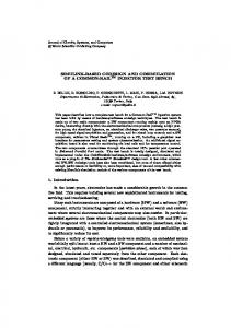
Torus Model Validation Study
After implementing the torus model, we set out to validate the models behavior and performance against an existing torus network. There were two parts to the validation study. First, we verified that the torus network model agrees with Little’s Law under a variety of torus configurations and packets arrival rates. Second, we compared MPI Send()/MPI Recv() latency times of the actual Blue Gene/L network using 2K processors (1,024 node torus, 1x32x32) and experimental runs of our torus network model for the same torus configuration [10]. We conducted MPI ping-pong tests on Blue Gene/L and compared them to a ping-pong simulation. The results of this experiment are illustrated in Figure 3. The ping-pong experiments measured communication times between nodes on the Blue Gene/L torus and the ROSS-based torus mode. We configured a 250-byte torus message to ensure we used Blue Gene’s eager communication protocol. We varied the distances between the two communicating nodes in the torus to use either two or eight node hops across the torus network. Our torus network model delays are equivalent to that of the Blue Gene/L machine with the two-hop case. Our model results diverge from the observed Blue Gene/L results for the eight-hop case. We believe the difference lies in routing optimizations made by the Blue Gene network that enable it to
128
256
512
pakcet size /Byte
arrive
Figure 2: Discrete-Event Torus Network Model.
4.2
latency /ʅs
10
Figure 3: Comparison of Torus Network Latency: Blue Gene/L torus VS. simulation. exceed the network performance of what our model predicts. The model performs congestion queuing correctly and will be sufficient at predicting storage architecture performance. The time to commit data to RAM disk, SSD, or hard disk ranges from hundreds of microseconds to milliseconds. The torus network model error of two microseconds for a two-hop torus network message is negligible for our exascale storage modeling purposes.
4.3
Torus Model Scaling Study
After verifying the behavior of the torus model, we analyzed the performance of the torus network at an extremescale of one billion nodes. As our model approaches one billion nodes, the simulation requires significant amounts of memory to execute. Simulating this model on Blue Gene/L requires at least 4,096 processors and 2TB of memory. We evalauted the strong-scaling characteristics of the torus model at 8,192 and 16,384 processors. The results of this study are shown in Table 1 and 2. The total number of generated packets in these experiments is O(1011 ) and the total number of events scheduled is O(1013 ). This extreme-scale torus model can sustain a continuous packet stream of 1011 packets per second. The efficiency appears lower at 16,384 processors for the 200 packet per nanosecond scenario when compared to our 16-million-node torus model experiments [10]. This is attributed to the onebillion node torus model being under-loaded with packets relative to the 16-million node torus model. In the absence of queuing effects, events are scheduled closer together in simulated time for the 1-billion node torus model. This behavior leads to a higher rollback probability. The overall loss in event-rate performance is attributed to the larger event population. The additional RAM requirements for this model increases queuing overheads and leads to larger cache-memory overheads.
4.4
Torus Model Integration
After validating the model execution behavior and verifying it’s performance characteristics, we integrated the torus model into an existing storage system. The goal for this model integration activity was to verify that the model could be used to transfer actual storage system network traffic and to demonstrate the models usefulness for evaluating storage system software using simulated networks. By coupling the torus model to the existing storage systems, it is possible to
Table 1: Strong scaling performance of 1-billionnode model at configuration 326 with packet arrival rate of 200pkt/ns. number of processors 4,096 8,192 16,384 number of packets (G) 40 40 40 efficiency 97.05% 96.00% 81.90% event-rate (M/sec) 639 1,066 1,681 remote event percentage 11.72% 12.41% 13.79% secondary rollback rate 0.0286% 0.0347% 0.220% number of event (G) 5,644 5,644 5,644
Table 2: Strong scaling performance of 1-billionnode model at configuration 326 with packet arrival rate of 400pkt/ns. number of processors 4,096 8,192 16,384 number of packets (G) 80 80 80 efficiency 97.33% 96.81% 96.42% event-rate (M/sec) 638 1,241 1,966 remote event percentage 11.72% 12.41% 13.79% secondary rollback rate 0.0268% 0.0312% 0.0245% number of event (G) 11,442 11,442 11,442 evaluate next generation and revolutionary techniques for exascale storage systems. There are two requirements to ensure that storage system functions correctly when using the torus model. First, the messages transfered between the storage system nodes must be valid. The generated message traffic between the storage system instances cannot be simulated and must be correctly formatted messages with real payload data. Second, the storage system prototype most provide a ROSS-enabled network resource that is compatible with other network resources used by the storage system. While the storage system provides several I/O resources with consistent resource access interfaces, the underlying transport layer for each network resource varies. For example, MPI-based and ROSSbased network resources are available for the prototype storage system.
Prototype I/O and Storage System Instance
Prototype I/O and Storage System Instance
Network Resource
Network Resource
CODES I/O Model
...
CODES I/O Model
CODES Torus Model
...
CODES Torus Model
MPI
...
MPI
Figure 4: Integration of CODES torus model into storage system prototype. Figure 4 illustrates how the CODES torus model integrates
with the prototype storage system. To integrate the ROSSbased torus model into the prototype storage system, we modified the ROSS network resource to include the torus model. Since, this ROSS network resource simulates network transfers issued by the storage system, the torus model intercepts the communication requests and simulates the traffic across the torus. Additionally, the ROSS network resource ensures that the actual message payload is correctly received at the receiver while the torus model simulates data transfers using empty message payloads. The ROSS network resource interacts with the torus model (using the torus model API) to translate the storage system messages into messages that conform to the torus model communication requirements. The ROSS network resource coordinates the transfer of data across the torus and signals the receivers ROSS network resource when the transfer is complete. The end result of this simulation setup is that the storage system issues network transfer requests, simulates the transfers across the torus model using fake data payloads, detects when the storage system message transfer is complete, and delivers the actual message to the remote storage system instances.
5.
CONCLUSIONS AND FUTURE WORK
We are still in the early stages of the CODES project and have completed several milestones. We completed the development of our first model for an exascale storage system with the ROSS-based torus model. We integrated this model with an existing storage system prototype and demonstrated the use of the torus model within a systems software tool. We are currently developing additional CODES models to compliment our torus model. We are integrating this model with additional systems software tools. Currently, we are integrating CODES and ROSS with the I/O Forwarding Scalability Layer (IOFSL) [13, 3]. Using the CODES tools, we will analyze several algorithms to address scalable fault tolerance within exascale storage systems.
Acknowledgements This work was supported by the Office of Advanced Scientific Computer Research, Office of Science, U.S. Dept. of Energy, under Contract DE-AC02-06CH11357.
6.
REFERENCES
[1] H. Abu-Libdeh, P. Costa, and A. Rowstron. Symbiotic routing in future data centers. In ACM Conference on Special Interest Group on Data Communication (SIGCOMM’10), pages 51–62, New Delhi, India, Aug. 2010. [2] A. Agarwal. Limits on interconnection network performance. IEEE Transactions on Parallel and Distributed Systems, 2(4):398–412, 1991. [3] N. Ali, P. Carns, K. Iskra, D. Kimpe, S. Lang, R. Latham, R. Ross, L. Ward, and P. Sadayappan. Scalable I/O Forwarding Framework for High–Performance Computing Systems. In IEEE International Conference on Cluster Computing 2009, 2009. [4] J. Bent, G. Gibson, G. Grider, B. McClelland, P. Nowoczynski, J. Nunez, M. Polte, and M. Wingate. PLFS: A checkpoint filesystem for parallel
[5]
[6]
[7] [8]
[9]
[10]
[11]
[12]
[13]
[14]
[15]
[16]
applications. In Proceedings of the Conference on High Performance Computing Networking, Storage and Analysis (SC ’09), New York, NY, USA, 2009. ACM. T. Blog. About 16 and 17 core processors. http://www.top500.org/blog/2010/12/06/about_ 16_and_17_core_processors, 2010. C. Carothers, D. Bauer, and S. Pearce. ROSS: A High-Performance, Low memory, Modular Time Warp System. Journal of Parallel and Distributed Computing, (62):1648–1669, 2002. DOE. ”Sequoia” draft statement of work. https://asc.llnl.gov/sequoia/rfp/, 2008. HPCWire. Lawrence livermore prepares for 20 petaflop blue gene/q. http://www.hpcwire.com/features/ Lawrence-Livermore-Prepares-for-20-Petaflop-Blue-GeneQ-38948594. html, 2009. J. Kim, W. J. Dally, B. Towles, and A. K. Gupta. Microarchitecture of a high-radix router. In Proceedings of the 32nd International Symposium on Computer Architecture (ISCA’05), Madison, Wisconsin, USA, June 2005. N. Liu and C. Carothers. Modeling billion-node torus networks using massively parallel discrete-event simulation. In Proceedings of 25th IEEE/ACM/SCS Workshop on Principles of Advanced and Distributed Simulation , 2011. G. Mora, J. Flich, J. Duato, P. Lopez, and E. Baydal. Towards and efficient switch architecture for high-radix switches. In ACM/IEEE Symposium on Architectures for Networking and Communications Systems (ANCS’06), pages 11–20, San Jose, California, USA, Dec. 2006. A. Nisar, W. K. Liao, and A. Choudhary. Scaling Parallel I/O Performance Through I/O Delegate and Caching System. In SC ’08: Proceedings of the 2008 ACM/IEEE conference on Supercomputing, 2008. K. Ohta, D. Kimpe, J. Cope, K. Iskra, R. Ross, and Y. Ishikawa. Optimization Techniques at the I/O Forwarding Layer. In IEEE International Conference on Cluster Computing 2010, 2010. T. Register. IBM uncloaks 20 petaflops bluegene/q super. http://www.theregister.co.uk/2010/11/22/ ibm_blue_gene_q_super/, 2010. J. Shalf, S. Kamil, L. Oliker, and D. Skinner. Analyzing ultra-scale application communication requirements for a reconfigurable hybrid interconnect. In Proceedings of the 2005 ACM/IEEE Super Computing (SC’05), Seattle, Washington, USA, Nov. 2005. V. Vishwanath, M. Hereld, K. Iskra, D. Kimpe, V. Morozov, M. Papka, R. Ross, and K. Yoshii. Accelerating I/O Forwarding in IBM Blue Gene/P Systems. In SC 2010, 2010.
The submitted manuscript has been created by UChicago Argonne, LLC, Operator of Argonne National Laboratory (“Argonne”). Argonne, a U.S. Department of Energy Office of Science laboratory, is operated under Contract No. DE-AC02-06CH11357. The U.S. Government retains for itself, and others acting on its behalf, a paid-up nonexclusive, irrevocable worldwide license in said article to reproduce, prepare derivative works, distribute copies to the public, and perform publicly and display publicly, by or on behalf of the Government.