Collision Free Object Movement Using Vector Fields Parris K. Egbert and Scott H. Winkler Computer Science Department 3328 TMCB Brigham Young University Provo, UT 84602
[email protected],
[email protected]
Abstract The topics of computer animation and object collision detection and resolution have become increasingly desirable in a wide range of applications including autonomous vehicle navigation, robotics, and the movie industry. However, the techniques currently available are typically difficult to use or are restricted to a particular domain. This paper presents a technique for providing automatic animation and collision avoidance of arbitrary objects in a computer graphics system. The underlying construct used in this process is a surrounding volume octree vector field. The system automatically generates these structures around objects in the scene. By judicious creation and use of these vector fields, objects in the scene move and interact, but do not collide. The manner in which these vector fields are created is given. Two applications - cloud movement over terrain and autonomous aircraft navigation - are presented which show typical usage of this technique.
Keywords Computer graphics, animation, collision avoidance, vector fields. 1. INTRODUCTION Computer animation has become widespread in its usage among a broad range of applications. Extensive research has been devoted to animation systems and techniques. However, the task of animating objects in a scene remains a fairly low level, tedious exercise. In addition to general animation capabilities, many applications desire automatic collision detection coupled with collision avoidance or collision resolution. Research in these areas has produced systems in which these capabilities exist, but they are typically difficult to use and are not extendible to other domains. This paper presents a technique for automatically providing animation and collision avoidance in a general computer graphics system. The technique allows users to easily set up and animate objects, then prevents objects from colliding as the animation proceeds. This is done through an expanded notion of vector fields. Vector fields are established in a scene, along with the objects comprising the scene. These vector fields affect object motion and animation, and also provide for automatic collision avoidance. Applications of collision avoidance in an animation system include any scene where there is object movement above or around other objects. Examples of this are a plane flying low over the ground, cloud movement over land, or the movement of flocks of birds or schools of fish.
1
2. OVERVIEW Collision avoidance is the collision-free movement of two or more objects. Collision avoidance techniques can be classified into one of two categories. The first category includes the continuous motion or path planning techniques. The second category is the group of static collision detection algorithms. These methods solve a series of static (non-moving) states to check for imminent collisions and to take steps to avoid them. Continuous motion or path planning problems are characterized by the requirement that each object's position and velocity be known a priori. Collisions are prevented by choosing paths where no collisions occur. This is done by analytically calculating paths using various methods. One example of the path planning techniques is the generate and test paradigm [1]. In this method each object is given a priority. Object paths are generated one at a time based on priority. Once a path has been generated, the system tests for intersections with existing object paths. If an intersection is found, the object's path is altered and the process is repeated. If no intersections exist, the system moves to the next object and the performs the process on the next object in priority. A variation of this technique is the configuration space approach [2]. In this technique the moving object is reduced in size to a point while obstacles are "grown" or increased in size proportional to the amount the moving object was reduced. The collision avoidance problem remains the same but the moving object can now be treated as a point. In this "configuration space" the collision free path is then obtained by connecting straight lines to the vertices of the grown obstacles and the start and goal positions. This technique is difficult to extend to 3D and also has the undesirable effect of generating paths that hug obstacle contours. Cameron proposed another path planning technique termed 4-dimensional intersection testing [3]. In this method time is added as a dimension to objects. The objects are then extruded by the time dimension and new 4-dimensional objects are formed. Intersections are then found between the new 4-dimensional objects. If no intersections are detected then the paths of the objects are collision free. The main limitation of the approach is in terms of the shapes and motions it can consider. Simple shapes with linear motion perform well under this scenario but more complicated objects or paths are not handled as well. A variation of this technique also proposed by Cameron takes a three-dimensional object and generates a new three-dimensional object that contains the volume swept out by the object over time [4]. If objects collide then their sweeps must intersect. This approach is very intuitive but has its limitations. One problem is the difficulty in explicitly representing the swept volumes. The other is the lack of temporal information in the intersection test. The strength of path planning techniques is their high degree of accuracy. Potential collisions are not missed and the chosen paths are often optimal. There are several weaknesses to path planning techniques, however. The most important is the requirement of a priori knowledge of an object's position and velocity. Another weakness is computational complexity. Another serious limitation of some of the path planning techniques is that they deal with only one moving object - all other objects must remain stationary. The second general category of collision avoidance algorithms is the static collision detection schemes. These schemes freeze objects at particular instances of time and check for intersections at those times. Once the objects are frozen, intersection tests are performed to detect any overlap between objects. If objects are found to overlap, their positions are altered to simulate the collision and the process is repeated. One collision detection technique that uses this approach is described by Cameron in [4] . This method considers the positions of objects at a number of time steps over the time-span of
2
interest, checking at each time step to determine if the objects intersect. If a collision is detected the object is returned to its prior collision-free state, which has been saved expressly for this purpose, and its path is altered to avoid the collision. Another static test technique of this type, proposed by Khatib [5], uses an artificial potential field to prevent collisions. In this system objects are given a goal location and started in motion toward that location. Obstacles are surrounded by repulsive forces while the goal attracts the moving object. When the moving object approaches an obstacle a force is imparted on it that is the combination of the goal's attracting force and the obstacle's repulsive force. The repulsive force increases as the moving object approaches the obstacle's surface. The resultant force keeps the moving object from colliding with obstacles while it moves toward its goal location. One problem with this approach is that the potential field function requires obstacles to be described by the composition of primitives. For complex objects these descriptions may become large and unwieldy. In addition, since forces are determined only by the proximity of the obstacles, the algorithm may fail. Krogh extended Khatib's work by including not only position but also velocity in the computation of the potential field [6]. This approach, as well as that proposed by Khatib, assumes a known and prescribed world model of all objects. This is much too restrictive for the environment we desire. Borenstein and Koren [7] use a similar idea with a mobile robot by having the repulsive forces determined by the strengths of the sensor data of the robot. Rather than use an analytical function to increase the repulsive force of an obstacle as an object approaches it, Borenstein and Koren use the "certainty" of an obstacle's existence as determined by the robot's sensors. The closer the robot approaches a wall, the stronger its sensor readings of the wall and hence the stronger the repulsive force exerted by the algorithm. This approach is limited to the 2-dimensional space of a mobile robot, however. In addition, the repulsive force is calculated using feedback from sensory instruments mounted on the robot. This method would not work for a computer simulated environment. The strengths of the static collision detection approaches are that they do not require a priori knowledge of an object's position and velocity and that multiple moving objects can be handled in a natural manner. The major weakness of static collision techniques is that, due to their discrete nature, collisions may be missed. This could happen if one or both of the objects that collide move quickly enough from one time step to the next that they move from a non-intersecting state completely through one another to another non-intersecting state. 3. COLLISION AVOIDANCE USING VECTOR FIELDS This paper presents a new method of performing collision avoidance that is suitable to applications in animation. The main goals of this work are to provide automatic collision avoidance between multiple moving objects such that real time performance can be maintained, and such that the techniques are easily usable by naive users. In order to achieve these goals, a modified static collision technique was chosen. Continuous collision avoidance techniques were discarded due to their limitations in the number of moving objects allowed and in the time requirements typical of these techniques. The approach taken in this work is to automatically surround objects in a scene with repulsive vector fields. Once the animation is begun, the objects will move through the environment, being influenced by the vector fields in their vicinity. As two objects approach one another, their repulsive vector fields will interact and cause the objects to move away from one
3
another. These vector fields will be automatically generated for the objects. Thus, the user will simply set up the environment. The system will generate the vector fields, provide the object animation, and perform the collision avoidance computations. A vector field is defined as follows: Let G be a subset of R3. A vector field on R3 is a function F that assigns each point (x1, x2 , x3 ) in G a three - dimensional vector F(x1, x2 , x3 ). Much of the research done to date in vector fields has been directed toward developing techniques to visualize the vector field itself [8, 9]. This work expands the role of vector fields to active entities in the animation system. Vector fields are placed in the environment, then when objects enter into a vector field, the motion of the objects are altered according to vector field forces present at the intersecting locations. The specific thrust of this work is the manner in which vector fields are used to enclose objects so as to provide repulsive forces around those objects. Once these repulsive fields have been established, the objects are set in motion and move according to the combined forces of all vector fields present at their current location. By correctly constructing the enclosing vector fields, the objects in the scene move in a collision-free fashion. There are three main issues involved in building the repulsive vector fields. The first is in determining how to specify the bounds of the influence of the vector field around an object. The second is the manner in which the repulsive vector directions are to be computed. The third is in determining the strengths of the vectors. Since we desire objects to move in a collision free environment, the strength of the vector field must vary according to the distance of approaching objects. We have resolved the first issue, that of determining the bounds of the influence of a vector field, by enclosing each object in a surrounding volume prior to repulsive vector field generation. This surrounding volume does not tightly enclose the object, but rather provides a user-specified area of "dead space" between the exterior of the object and the edges of the surrounding volume. This ensures that other objects that approach this object, and have the potential of colliding with it, will enter the area of influence of the object's repulsive force before a collision occurs. The force of the object's vector field will then act upon the approaching object and alter its motion so as to avoid a collision. The second issue involves computing the vector directions for the repulsive vector field. These forces need to be such that approaching objects that fall within the influence of this object's repulsive force will have their motions altered appropriately such that collisions will be avoided and also such that object movement will look natural. The vector direction should vary according to the shape of the object. Thus, the repulsive vector directions need to be determined based on the characteristics of the object nearest the point of approach of the potentially colliding objects. The approach we have selected for this is based on an octree subdivision method. The surrounding volume of the object is recursively subdivided into octants. Suboctants of the octree are further sub-divided based on how much of the object falls within the octant. Once the octree subdivision is complete, a repulsive vector is assigned to each node of the octant. This "octree-vector field" then provides the repulsive force for the object. This method was chosen because of the octree's ability to form around any object, the speed at which locations within the octree can be found, and the ease of its construction. An object is initially introduced into the system, either by defining the object in the system, or by inputting an existing external object. Next, the object is converted into a triangular mesh so
4
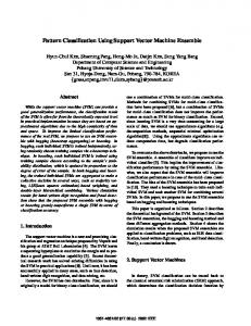
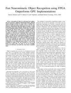
that the system has a uniform object type with which to work. A third, optional, step in the preparation of the object is to tessellate the triangle mesh into a finer mesh of approximately uniform size. This step is not always necessary, but is provided in the system as an additional method of assuring uniform distribution in the octree. This provides for a more accurate octreevector field. Once object preparation is complete, the triangle mesh can then be used in the octree generation. The octree generation algorithm is begun by enclosing the object in a suitable surrounding volume. That surrounding volume is then subdivided into octants. The octree constructed is an Nobjects octree, meaning the surrounding volume is recursively subdivided into smaller cubes until no more than N pieces of the object's triangular mesh lie in any one octant. An example of the subdivision using an N-objects quadtree, the two-dimensional equivalent of the octree, is shown in Figure 1. In this example, each line of the figure is actually defined as many smaller line segments (imitating the 3D equivalent, the subdivided triangular mesh). This quadtree is a 6-object quadtree with a depth of 4. Once the octree is created around the object, forces are assigned to each octant of the octree. Since these forces will be the repulsive forces surrounding the object, we desire them to have directions that will "push" approaching objects away from this object. The direction will be a function of the normals of the objects contained in an octant. Due to the N-objects criteria of subdivision, at the completion of the subdivision each leaf octant will have N or fewer triangles of the triangular mesh within it. For octants which contain one or more triangles, the normal vector of each triangle in the octant is calculated. These normals are then averaged and normalized to determine the repulsive direction for the octant. A 2D object for which a quadtree and the resultant force vectors are computed is pictured in Figure 2.
Figure 1. Quadtree around a 2-dimensional object.
5
Figure 2. An example of a quadtree representation of a vector field.
This technique works for octants which contain part of the object, but for octants which do not contain any part of the object, repulsive forces must be computed differently. The forces are calculated as the octree is constructed so that interior octants, octants which are not leaf nodes in the final representation but were at some point in the octree construction, have forces determined for them as well. This is useful for determining the force in an octant in which no polygons of the object's triangular mesh lie. The repulsive direction is determined as a function of all of the object's pieces that were contained in the octant's parent node--the interior node one subdivision level before that of the octant in question. An example is shown in the quadtree example of Figure 3. As can be seen, the corner quadrant, highlighted by dashed lines, does not contain any portion of the object. The force of this quadrant is determined by the force that would have been assigned to its parent, the quadrant highlighted by bold lines, if the parent had been a leaf node. This repulsive direction is computed as the average normal of all object pieces that fall within the parent octant. Once all the octree forces have been calculated the values for interior nodes are discarded, since only octree leaf nodes are used in the ensuing computations.
6
Empty leaf quadrant
Parent or interior quadrant
Figure 3. Calculation of force for empty leaf quadrant. After the direction of the repulsive force has been determined the last step in constructing the octree-vector field is to determine the strength of the forces. Since the goal is to ensure that objects do not collide, the strength of forces repelling objects should increase as the objects draw nearer, tending toward infinity as the surfaces come into contact. The octree-vector field algorithm provides a natural mechanism on which to base a heuristic that increases the repulsive force as the surface of the object is approached. For this work the heuristic of increasing the force linearly according to the depth of the octree was used. In octants actually enclosing portions of the surface area the repulsive force is increased by an order of magnitude to simulate forces at infinity. The high force near an object's surface is to ensure as much as possible that objects do not collide or interpenetrate. Although collision avoidance is not absolutely guaranteed by this technique, we have found that it works well in practice. Collision avoidance is further facilitated by providing a sufficiently large surrounding volume around the object in question. This provides approaching objects with gradual increments in the magnitude of the repulsive force they experience. With the force magnitudes in place, the octree vector field construction is complete. Building this construct for the objects in the scene allows those objects to move through the environment in a collisionfree manner. With these octree vector field objects in place, object intersection testing can then be performed. The intersection test is accomplished by means of an octree hit test. This is a simple and fast intersection test. To prevent two objects from colliding the component triangles of the first object are tested against the octree of the second object. Each triangle is treated as a point with coordinates at the center of the triangle. Each "point" is tested against the top level internal octree node of the second object. If the triangle does not lie within this top level it is discarded and the next triangle in the triangle mesh is checked. If a triangle does lie within the top level of the octree we proceed to perform the intersection check against the sub-octants of the highest level octant. This process is repeated until a leaf octant is reached. Once it is determined that a triangle intersects a leaf octant node, the normalized force direction of the leaf octant and the depth of the leaf node are recorded. This process is repeated for each triangle in the mesh, at which time the 7
resultant force to be applied to the object is determined. The direction of this final force is computed by taking the average direction of the forces from all octants that had successful intersection tests. The magnitude of the force is computed as a function of the greatest leaf octant depth of the octree for which there was a successful intersection test. The application of this force causes the two objects to move apart and avoid collision. 4. SAMPLE APPLICATIONS This section presents slides of two animation sequences generated using the techniques developed in this paper. The demonstration was generated using the POOMA animation system [10]. The functionality built into POOMA allows the user to include vector field areas into the environment. In the first animation sequence, two cubic vector fields are used to simulate gravity and wind. Gravity is simulated by creating a uni-directional vector field in which all vectors inside this field have directions pointing directly downward. This vector field encompasses the entire environment. The wind vector field was also created using a uni-directional vector field, but in this case the vectors all point horizontally from right to left. In addition to these vector fields, a repulsive vector field was generated around the terrain using the techniques described previously. With these three forces in place, an object introduced into the environment should flow across the terrain from right to left in a collision-free fashion. In the simulation shown in Figure 4, a cloud object, comprised of many spherical shaped particles, was introduced into the environment. Figure 4a shows this initial setup. Once the objects and vector fields are in place, the animation is begun. Figure 4b shows the scene shortly after the animation sequence is begun. The wind force has commenced pushing the cloud across the terrain. At the same time, the repulsive force of the terrain has begun to deform the cloud. The gravitational force acts as an equalizing force to keep the cloud from accelerating upwards out of the environment. As the animation proceeds ( Figures 4c through 4i), the cloud moves across the surface of the terrain and deforms to roughly follow the contour of the terrain, as computed by the vector forces. Figures 4e through 4g show the cloud being compressed as it flows through a valley in the terrain. Figures 4h and 4i then show the cloud expand as it clears the mountain ridge. Finally, in Figure 4j, the cloud begins to exit the scene. The movement of the cloud across the landscape is performed automatically by the system. The user simply sets up the environment and begins the animation. The details of particle movement and force determination are done completely by the system. The second application shows the automatic navigation of an airplane through a mountainous region. In this simulation, a terrain object is generated along with its repulsive octree-vector field. A gravitational vector field is placed in the environment which encompasses the entire scene. An airplane object is placed in the scene near the left end of the terrain, and a driving force vector field is included that will push the airplane through the terrain. The overhead view of this animation is shown in Figure 5. Figure 5a shows the airplane in the canyon with mountains to the top right and the bottom left of the airplane. Figure 5b shows the position and orientation of the airplane shortly after the animation has commenced and the forces in the environment have begun to exert their influence on the airplane. Figure 5c shows the airplane as it begins to navigate around the bend in the canyon. Figures 5d through 5f show the airplane position and orientation after the corner has been successfully navigated. Again, all the user does is set up the environment. The actual flight of the airplane is computed entirely by the system. The images shown in Figure 5 represent six snapshots of a longer animation in which the airplane successfully
8
navigated its way through several turns in the terrain. In this animation, the airplane is treated as a single entity. Orientation of the airplane is not determined by the collision avoidance scheme, but is handled outside of that subsystem.
a.
b.
c.
d.
9
e.
f.
Figure 4. Animation of cloud movement over a landscape.
g.
h.
10
i.
j.
Figure 4 (continued). Animation of cloud movement over a landscape.
a.
b.
c.
d. 11
e.
f.
Figure 5. Animation of an airplane through a canyon. 5. SUMMARY AND CONCLUSIONS This paper develops a new technique for performing collision avoidance. The application of this technique to animation is emphasized in this work but there are also potential applications to numerous other areas, including robot and robot arm motion planning and autonomous navigation. The main goal of this work has been to create a system in which animation and collision avoidance for any number of objects is provided automatically by the system. This means that the user merely sets up a scene and then begins the animation without having to explicitly specify object paths. The system has the responsibility of ensuring that collisions between objects are avoided. The manner in which the system accomplishes this goal is through the use of octree-vector field surrounding volumes. Objects in the scene are placed in their individual surrounding volumes. Each volume completely encloses its object and has additional empty space, as specified by the user. The surrounding volumes are subdivided in an octree fashion. Each octant of the octree is assigned a force vector whose direction is determined as a function of the normals of the object in the vicinity of the octant, and whose magnitude is computed as a function of the level of the octree at which the octant resides. When an approaching object enters an octant of the octreevector field, the force of the intersected octant is applied to the approaching object to repel the object. This technique has allowed us to perform collision free animations of objects in a scene. Since repulsive octree-vector fields and the forces applied to objects are computed automatically by the system, the user need only set up the scene, place vector field forces (such as gravity or wind) at desired locations, and begin the animation. There are several areas of possible improvement in the algorithm elaborated in this paper that could be explored. The first area of possible improvement is the method in which the octree repulsive field itself is calculated. This paper presents a method to calculate the octree vector field
12
based on the normal vectors of the object. Other techniques could be explored which give a better approximation. Another area of potential improvement is in the determination of the strength of the forces within the octree vector field. This paper uses a heuristic that approximates forces in the octree. Some study in this area would facilitate calculating a more rigorously defined strength of force value and could improve the current algorithm. 6. ACKNOWLEDGMENTS We would like to thank Travis Hilton, who provided the framework for this project in his POOMA work. In addition, Dan Olsen provided several interesting insights and suggestions. This work was funded in part by WordPerfect, Inc., now a subsidiary of Novell.
13
REFERENCES 1. M. Erdmann and T. Lozano-Perez, "On Multiple Moving Objects," Proceedings IEEE International Conference on Robotics and Automation, Vol 3, pp. 1419-1424, April 1986. 2. S.H. Whitesides, "Computational Geometry and Motion Planning," in Computational Geometry, G. T. Toussaint ed., Amsterdam: North-Holland, pp. 377-427, 1985. 3. S. Cameron, "Collision Detection by Four-Dimensional Intersection Testing," IEEE Transactions on Robotics and Automation, Vol. 6, No. 3, pp. 291-302, 1990. 4. S. Cameron, "A Study of the Clash Detection Problem in Robotics," Proceedings IEEE International Conference on Robotics and Automation, pp. 488-493, March 1985. 5. O. Khatib, "Real-Time Obstacle Avoidance for Manipulators and Mobile Robots," Proceedings IEEE International Conference on Robotics and Automation, pp. 500-505, March 1985. 6. B.H. Krogh, "Integrated Path Planning and Dynamic Steering Control from Autonomous Vehicles," Proceedings IEEE International Conference on Robotics and Automation, pp. 16641669, April 1986. 7. J. Borenstein and Y. Koren, "Real-Time Obstacle Avoidance for Fast Mobile Robots," IEEE Transactions on Systems, Man, and Cybernetics, Vol. 19, No. 5, pp. 1179-1187, 1989. 8. W.J. Schroeder, C.R. Volpe, W.E. Lorensen, "The Stream Polygon: A Technique for 3D Vector Field Visualization," Visualization '91, IEEE Computer Society Press, San Diego, California, pp. 126-132, October 22-25, 1991. 9. B. Yamrom and K.M. Martin, "Vector Field Animation with Texture Maps," IEEE Computer Graphics and Applications, Vol. 15, No. 2, pp. 22-24, 1995. 10. T.L. Hilton and P.K. Egbert, "Vector Fields: an Interactive Tool for Animation, Modeling and Simulation with Physically Based 3D Particle Systems and Soft Objects," Proceedings of Eurographics 94, Computer Graphics Forum, Vol. 13, No. 3, pp. 329-338, 1994.
14