Abstract. A combined optimal control method for robot manipulators is presented. The .... Therefore, this algorithm can be applied for each robot arm with any number of degrees of freedom. ...... IRB140CR.ppt (available Feb. 2, 2011). Received ...
Acta Technica 56 (2011), 23–42
c 2011 Institute of Thermomechanics AS CR, v.v.i.
Combined optimal control technique for robot manipulators 1 Abbas Chatraei 2 , Václav Záda2
Abstract. A combined optimal control method for robot manipulators is presented. The approach includes iterative linearization (IL), iterative learning control (ILC) and parametric optimization. The robot is assumed to perform a repeated task such as pick and place parts in an assembly line. Accordingly, in each trial in which the robot performs the task, a linear time variant (LTV) version of its nonlinear dynamics model is obtained (using IL) and at the same time an optimal control input for this LTV is computed by a parametric optimization method. The optimal solution of each trial is stored in memory of the system to compute the optimal solution in the next trial (ILC). This procedure is repeated so that after a finite number of trials, the sequence of optimal solution of LTVs converges to the robot’s optimal control input. Two outstanding features of this method consist in the fact that the optimal control problem is solved gradually during some trials while the time necessary to compute the optimal control input is divided into some trials, and that the optimal solution of each trial is used as the initial guess of the next optimization problem. Hence, the global optimal solution is finally achieved. Key words. Robot manipulator, optimal control, iterative linearization, spline function, performance criterion.
1. Introduction With growing of applications of robot manipulators in industrial factories, a key feature which has come under consideration is high productivity with low energy consumption as much as possible. This is the task of optimal control to solve this problem. Generally, an optimal controller steers a dynamical system from its initial state to the final with minimum cost which can be time, energy consumption or others. Depending on the type of the system which 1 This study is co-financed from the student grant SGS 2010/7821 “Interactive mechatronics systems using the cybernetics principle”. 2 Faculty of Mechatronics, Technical University of Liberec, Studentská 2, 461 17 Liberec 1, Czech Republic; e-mail: {abbas.chatraei , vaclav.zada}@tul.cz
http://journal.it.cas.cz
24
A. CHATRAEI, V. ZÁDA
is either continuous or discrete, there are corresponding methods to solve the optimal control problem (OCP), i.e. dynamic programming, indirect and direct methods. In discrete dynamic programming, the principle of optimality is used as the base and then Bellman’s recurrence equation is applied to calculate the optimal control history [1], [2]. On the other hand, for continuous time systems the Hamilton–Jacobi–Bellman equation is used to compute the optimal control input. Indirect methods represent another general class such that the calculus of variations and Pontryagin’s maximum principle are its subbranches. If the OCP is unconstrained, i.e., no constraint exists on the value of controls and states of the system, then the Lagrange’s equation in calculus of variations can be utilized to compute the optimal control. Otherwise, in the case of constrained OCP, the Pontryagin’s minimum principle is used to design the optimal control law. Both Lagrange’s equation and Pontryagin’s minimum principle result in a two-point boundary value (TPBV) differential equation for which obtaining a closed form solution is usually impossible. Therefore, numerical methods such as steepest descent, variation of extremals, quasilinearization or gradient projections can be used to solve these TPBVs [3]. The other optimal control method is the direct one in which the basic idea is to convert the infinite-dimensional OCP into finite-dimensional in such a way that the nonlinear programming can be used to calculate the optimal control inputs [4]. Some of the methods mentioned above have also been employed to design an optimal controller for robot manipulators. The time OCP of robot manipulators was seriously considered by Bobrow in his Ph.D. dissertation [5]. He proposed a new method in which a modified Pontryagin’s minimum principle is used to calculate the optimal control torques of each joint of a robot manipulator. His proposal is summarized as follows: Suppose a robot manipulator the objective of which is to track a Cartesian path by its end-effector such that the traversal time from the initial point of the path to the final point is minimized. Let us now parametrize the Cartesian path so that by varying a parameter all of the points on the path can be defined. After that, dynamic equations of robot can be defined in terms of this path parameter so that they are reduced to a set of second-order differential equations as well as the constraints on the control torque inputs converted into constraints on the acceleration along the path. According to Pontryagin’s minimum principle, the optimal control of the system leads to bang-bang control in which the switching times can be obtained by means of a so called velocity limit curve that Bobrow obtained it by acceleration bounds along the path. After this proposed method, some other research was presented by which a set of improvements was applied to the Bobrow’s first work [6], for instance the singularity problem appeared in OCP [7], [8]. In the following, some of these studies are surveyed. In [9] the Bobrow’s method was used to solve the OCP of robot manipulators; however, for computing the optimal control a
CONTROL TECHNIQUE FOR ROBOT MANIPULATORS
25
dynamic programming algorithm was developed to derive the reduced set of second-order differential equations in terms of path parameter; in this way the problem of “curse of dimensionality” appearing in dynamic programming was solved. Therefore, this algorithm can be applied for each robot arm with any number of degrees of freedom. Different kinds of direct methods including single shooting, collocation and multiple shooting methods have been considered in details by [10] and eventually the multiple shooting has been used to calculate optimal control of a five degrees of freedom robot arm. It should be noted that the shooting method was first presented by [11]. A number of papers can be addressed in which the spline-based optimal control has been used [12], [13]. A spline-based optimal control together with a global optimization algorithm have been presented by [14] in which the presented algorithm can compute the optimal control in a fraction of a second to several seconds, depending on the type of robot structure. The outline of the present paper is as follows. In Sec. 2 we formulate the robot’s OCP. In Sec. 3 we present our optimal control approach together with applying the proposed method to two robots the second one of which is an ABB robot manipulator.
2. Formulation of robot optimal control The dynamics of an open-chain robot manipulator can be obtained by applying either Euler–Lagrange or Newton–Euler formulations [15]. By means of Euler–Lagrange formulation, the motion equation of a serial robot manipulator can be represented as follows: ˙ =τ , M (q)q¨ + N (q, q)
(1)
where q, q˙ and q¨ are the n-dimensional vectors of joint displacements, velocities and accelerations, respectively, M (q) is the n × n symmetric positive definite ˙ is the n-dimensional vector containing manipulator inertia matrix and N (q, q) centrifugal, Coriolis, gravitation and friction torques (see Appendix). Defining position/velocity state x ∈ R6 as �
x1 x= x2
�
� � q , = q˙
(2)
the state space representation of the system (1) may then be expressed as x˙ = f (x) + g(x)τ ,
(3)
26
A. CHATRAEI, V. ZÁDA
where �
� x2 f (x) = , −M −1 (x1 )N (x1 , x2 )
�
� 0 g(x) = . M −1 (x1 )
(4)
Now the optimal control of the robot manipulators may be formulated as follows: Our goal is to find an admissible input torque vector which steers the robot system (3) at a finite time in such a way that the cost function (performance criterion) given by Z tf � � J = ϕ x(tf ), tf + L x(t), τ (t), t dt (5) t0
is minimized, while the following constraints are met: x(0) − x0 = 0
initial state constraints ,
x (tf ) − xf = 0 final state constraints , � C x(t), τ (t) ≥ 0 state & control constraints .
(6)
It is worth noting that the cost functional used in the OCP of robots can be one of the following cases: • minimum time: Z tf J= dt = tf , tf is free , 0
• minimum energy consumption: Z tf X n �2 J= τi (t) dt , 0
• minimum power consumption: Z tf X n �2 J= q˙i (t)τi (t) dt , 0
tf is fixed ,
i=0
tf is fixed .
i=0
3. Proposed method for solving OCP of robot arms As mentioned above, the basic idea of the proposed method is to combine three techniques including iterative linearization, iterative learning control (ILC) and parametric optimization. Roughly speaking, the optimal control for nonlinear system (robot) is computed in several stages depending on the level of system nonlinearities. In other words, the nonlinear system is linearized in several steps so that in each step the original system is converted into a linear time variant (LTV) system and, simultaneously, an optimal control input is computed for each LTV by the parametric optimal control technique. Hence,
CONTROL TECHNIQUE FOR ROBOT MANIPULATORS
27
the original nonlinear system is converted into a sequence of LTV systems so that after a finite number of linearization steps, the sequence of LTV solutions and their optimal control input will converge to the solution and optimal control of the nonlinear system. This procedure entirely fits the application of robot manipulators in repeated tasks. Note that a stage should be added to the above procedure: firstly the state space representation of the nonlinear system (3) must be converted into the following form which is called state dependent coefficient (SDC) form x˙ = A(x)x + B(x)u ,
x(0) = x0 ,
(7)
where u = τ and ∂f1 ∂x1 ∂f2 A(x) = ∇x f (x) = ∂x1 . .. ∂fn ∂x1
∂f1 ∂x2 ∂f2 ∂x2 .. . ∂fn ∂x2
... ... .. . ...
∂f1 ∂xn ∂f2 ∂xn , .. . ∂fn ∂xn
B(x) = g(x) .
(8)
There are also some conditions which must be satisfied in the proposed method. Firstly without loss of generality x = 0 should be the equilibrium point of the system. Otherwise, we can apply a linear transformation to the dynamic system (3) so that the equilibrium point becomes zero. Secondly, to guarantee the convergence stated above, matrices A(x) and B(x) must be locally Lipschitzian. Also note that the LTV system in each stage of linearization, as hinted above, can be represented as follows: � � � � x˙ [i] (t) = A x[i−1] (t) x[i] (t) + B x[i−1] (t) u[i] (t) , x[i] (0) = x0 ,
i = 1, 2, . . . ,
(9)
where x[0] (t) can be an arbitrary initial guess and, for convenience, it may be considered as initial condition, i.e. x0 . In the subsequent subsection, we will show how the optimal control input is computed for LTV system (9). 3.1. Parametric optimization Let us now consider the parametric optimal control algorithm, used in the procedure mentioned above to compute the optimal control input for each LTV. The basic idea in the parametric optimal control is that the original infinitedimensional optimal control problem is converted into a finite-dimensional
28
A. CHATRAEI, V. ZÁDA
optimization problem (known as constrained nonlinear programming (CNP)) which can be solved by existing algorithms like sequential quadratic programming (SQP). The parametrization is usually made using the spline functions which can be either polynomial spline or B-spline functions. The reason is that they have sufficient attributes to converge to a good optimal solution in CNPs and their application results in faster convergence rate and better solution to the optimization problem. In the former splines the coefficients of polynomials are parameters and in the latter the control points are used as parameters which need to be optimized. In the case of OCP of robot manipulators stated in Sec. 2, the parametrization procedure is performed by considering the following polynomial spline function, as each joint position of the robot is s0 (t) s1 (t) qj (t) = .. . s` (t)
t 0 ≤ t < t1 , t 1 ≤ t < t2 , .. . t` ≤ t < t`+1 = tf ,
j = 1, 2, . . . , n ,
(10)
where si is a cubic spline function defined by 3
2
si (t) = p1i (t − ti ) + p2i (t − ti ) + p3i (t − ti ) + p4i
(11)
for i = 0, 1, . . . , `. According to (10), the joint velocity and acceleration expressions can be obtained by considering the following equations: 2
s˙ i (t) = 3p1i (t − ti ) + 2p2i (t − ti ) + p3i , s¨i (t) = 6p1i (t − ti ) + 2p2i .
(12)
To apply these cubic spline functions as the joint position trajectories of the robot, the following conditions should be satisfied: • • • •
the initial and final state constraints represented in (6) should be met; qj (t) should be continuous on the interval [t0 , t`+1 ] ; q˙j (t) should be continuous on the interval [t0 , t`+1 ] ; q¨j (t) should be continuous on the interval [t0 , t`+1 ] .
After fulfilling the conditions above, some of the coefficients p1i , p2i , p3i and p4i are dependent while the rest are independent. It can be shown that the number of independent coefficients used as the parameters in parametric optimization mentioned above is n`. After applying the joint position, velocity and acceleration terms represented above to each LTV (9) and solving these differential equations, the control input can be obtained in terms of independent parameters. If we then substitute parametric joint, velocity and control
CONTROL TECHNIQUE FOR ROBOT MANIPULATORS
29
input into cost function (5), we obtain a parametric function J(p) where p stands for independent parameters. Such substitutions can be repeated for constraints (6) and eventually we obtain a constrained optimization programming which should be solved. One of the useful tools to solve CNPs is the optimization toolbox of MATLAB specifically the function fmincon. The parametrization in robot OPC is usually done by polynomial spline functions, which have a property which is significant in the case of moving of robot manipulator. This property is that the changing a parameter affects the entire shape of the spline curve, while we need to alter a part of curve. This problem can be resolved using B-spline functions which have the following form: q(t, P ) =
m X
pj Bj,k (t) ,
(13)
j=0
where P = {p0 , . . . , pm } is the set of control points (which are used as parameters in parametrization procedure) and k is the order of the B-spline. In (13) a knot space is defined as t0 ≤ · · · ≤ tk−1 ≤ tk ≤ · · · ≤ tm ≤ tm+1 ≤ · · · ≤ tm+k , and Bj,k (t) is the B-spline basis function expressed recursively as Bj,k (t) =
tj+k − t t − tj Bj,k−1 (t) + Bj+1,k−1 (t) , tj+k−1 − tj tj+k − tj+1
(14)
where � Bj,1 (t) =
0
if tj ≤ t < tj+1 ,
1
otherwise .
(15)
In the case of robot manipulator’s OCP, the cubic B-spline functions (k = 4) are usually used to parametrize the joint variables, and the set of control points P is employed as parameters in the optimization problem [12]. 3.2. The proposed algorithm First of all, let us see the role of ILC in the proposed method. Roughly speaking, ILC is a control strategy which can be used to control the robot arms which perform a special task repeatedly like the tasks in assembly lines. To control such systems, Arimoto in [16] proposed ILC approach by which the performance of the system in each trial is improved regarding the tracking errors in the previous trials. In other words, the control input in each trial is computed considering the collected information from the previous trials. Such a procedure can be used in our method. We now develop an algorithm by which the optimal torques of the robot can be computed, considering that the task to be performed by robot is a repeated task. This algorithm is completed in the following steps:
30
A. CHATRAEI, V. ZÁDA
1. Obtain the state space representation and then the SDC form of robot manipulator system in question. 2. Guess an arbitrary state x[0] (t), t ∈ [t0 , tf ], and store it in the memory of the system. Let the iteration index i be one. 3. Using x[i−1] (t) and utilizing spline-based optimal control technique, compute the optimal torques/forces u∗[i] (t) and optimal states x∗[i] (t) of the LTV system in step i given in (16) below and store the optimal states x∗[i] (t) in the memory of the system; � � � � x˙ [i] (t) = A x[i−1] (t) x[i] (t) + B x[i−1] (t) u[i] (t) , x[i] (0) = x0
(16)
with the cost functional � � Z Ji = ϕ x[i] (tf ), tf +
tf
� � L x[i] (t), u[i] (t), t dt .
(17)
t0
4. Apply u[i] (t) to the ith trial of ILC scheme. 5. If
[i]
x (t) − x[i−1] (t) ≤ α ,
(18)
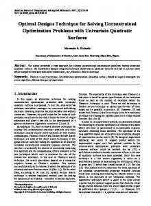
where α is a given constant, then terminate the computations; u[i] (t) can be used for the next trials in the ILC scheme. If stopping criterion (18) is not satisfied, then increase i by one and return to step 3 of the procedure. � After some finite number of trials, the sequence of x[i] (t) converges and � hence the optimal control u[i] (t) will be used as optimal control u∗ (t) in nonlinear system (3). Figure 1 indicates the proposed optimal control system. In the following, some examples will be brought to show the operation of the proposed method.
Fig. 1. The proposed optimal control system
CONTROL TECHNIQUE FOR ROBOT MANIPULATORS
31
3.3. Single link robot manipulator Let us consider a single link robot manipulator shown in Fig. 2 whose dynamic equation and state space representation are as follows: ¨ = − g sin θ(t) − v θ(t) + 1 u(t) , θ(t) l ml2 ml2
(19)
where m = 2 kg, l = 1 m and v = 6 kg m2 /s and considered states are x1 = θ, ˙ whereby x2 = θ, x˙ 1 (t) = x2 (t) , x˙ 2 (t) = −9.8 sin(x1 (t)) − 3x2 (t) + 0.5u(t) .
(20)
As seen, x = 0 is the equilibrium point of this system. The objective is to drive this system from initial states x1 (0) = 0, x2 (0) = 0 to final states x1 (2) = 0.4, R2 x2 (2) = 0 so that the cost functional J = 12 0 u2 (t)dt is minimized.
Fig. 2. One degree of freedom manipulator
For comparing the results of different optimal control methods, the OCP of this robot has been solved by analytical (Pontryagin’s minimum principle) method [17], multiple shooting method [10] and eventually using our proposed method. All the computations and simulations have been performed in MATLAB installed on an Intel processor of 2.2 GHz. Figures 3, 4 and 5 show the optimal angular position x∗1 , velocity x∗2 and applied torque u∗ computed by analytical, multiple shooting and our proposed algorithms, respectively (the asterisk denotes optimality in these figures). In this case the SDC form of (20) can be written as � � � �� � � � x˙ 1 0 1 x1 0 = + u. (21) x˙ 2 −9.8 cos x1 −3 x2 0.5 Note that the minimum cost value is 18.6225 and the number of polynomials for each spline function is 10 while the optimal control computation time for each step of the proposed method is 4.23 s.
32
A. CHATRAEI, V. ZÁDA
Fig. 3. Optimal solution of single link manipulator by analytical method (Pontryagin’s method)
Fig. 4. Optimal solution of single link manipulator by direct multiple shooting method
Fig. 5. Optimal solution of single link manipulator computed by the proposed method
CONTROL TECHNIQUE FOR ROBOT MANIPULATORS
33
Fig. 6. Difference between optimal states x∗1 (t) obtained from the last step of the proposed and multiple shooting methods and optimal states obtained by the analytical method
According to the above example the following features of the proposed method can be listed; • The method can handle each kind of constraints including control and state constraints. • In each trial, we should solve OCP for an LTV system instead of nonlinear system. • The number of iterations for SQP technique decreases compared to the nonlinear spline-based optimal control. This number for every trial is 18 while for nonlinear spline-based optimal control this value is 28. • According to the previous item, the necessary time for computations needed in optimization decreases. As mentioned earlier, this time in the case of multiple shooting is much greater than in the proposed method. • Figure 6 shows the difference between optimal states x∗1 (t) obtained from the last step of the proposed and multiple shooting methods and optimal states obtained by the analytical method. Since the analytical results were precise, the results of proposed and multiple shooting methods were compared with the results of analytical method. • The method produces both smooth controls and states. • The rate of convergence is almost high and actually after 3 or 4 iterations, the sequence of optimal control and states converges to optimal control and states of nonlinear system. • Changing the first and last polynomials in spline function results in the capability to handle arbitrary initial and final accelerations as well as jerks (rate of acceleration).
34
A. CHATRAEI, V. ZÁDA
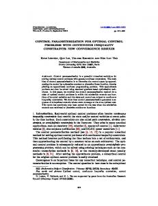
Fig. 7. ABB IRB140 robot manipulator
3.4. ABB IRB140 robot manipulator Let us now apply the proposed method to an ABB IRB140 robot manipulator, as shown in Fig. 7, which is an industrial robot having six degrees of freedom. The first three joints of this robot are used to position the endeffector, while the last three joints are employed to set the orientation of the end-effector. In the optimal control of robot manipulators the positioning part of the robot, i.e. three first joints, are usually considered. Accordingly, we can consider the ABB IRB140 robot as an arm with three degrees of freedom so that the orientation joints of the robot are fixed in their home positions. As will be seen later, for obtaining the dynamics model of the robot, we need the transformation matrices of this robot according to Denavit–Hartenberg convention. As illustrated in Fig. 7, the Denavit–Hartenberg parameters of this robot can be obtained as presented in Table 1. The dynamics model of this robot can be obtained according to Euler– Lagrange formulation [18]. We used the graphic user interface (GUI) to develop � an algorithm in MATLAB known as Dynamics robot modeler (DRM) , as shown in Fig. 8, which provides the Denavit–Hartenberg parameters of a robot and produces the dynamics equations of the robot. These equations are simplified by the MATLAB commands simple, simplify and vpa and eventually they are stored in some *.txt files, whose number is the same as robot degrees of freedom. These equations for ABB IRB140 robot are represented in Appendix. Let us now apply the proposed optimal control method to this industrial robot. As with DRM GUI mentioned above, we developed a GUI for computing the optimal results of industrial robots known as Robot Optimal Control
CONTROL TECHNIQUE FOR ROBOT MANIPULATORS
35
Table 1. Denavit–Hartenberg parameters of ABB IRB140 robot Link i 1 2 3
qi (rad)
di (m)
ai (m)
αi (rad)
π/2 π/2 −π/2
0.352 0 0
0.07 0.36 0.445
π/2 0 0
Solver (ROCS) depicted in Fig. 9. In this GUI, we can first select the robot type and then, entering the other data as represented in Fig. 9, the optimal results can eventually be obtained by clicking on Compute button. Notice that as mentioned above, we assumed that the first three joints of the robot and the joints associated with orientation of end-effector (wrist joints) were fixed in their home positions. Therefore, in this GUI we choose ABB IRB140 robot whereby the GUI considers the dynamics model of ABB IRB140 and then enters the rest of the data according to the following cost function and boundary conditions (given in Table 2): Z J=
10
2
τ12 + τ22 + τ32 + 0.001 (q1 − 0.3) +
0 2
2
+ 0.001 (q1 − 0.8) + 0.001 (q1 − 0.8) dt ,
(22)
where τ1 , τ2 and τ3 are the torques of the first three joints of the robot. Furthermore, the position and velocity constraints of this robot are listed in Table 3 [19]. Entering these data, the proposed optimal control results can be obtained by clicking on Compute button in ROCS GUI, where the optimal joint position, velocity and torque trajectories are produced as shown in Fig. 10. As seen in this figure, the proposed optimal control algorithm has been performed for ten trials so that the torque of the first joint converges after the third trial while for the second and third joints it converges after the second trial. Also the value of the cost function in the first trial is 4388.4 and this value for the rest trials is 2614.7, 2613.3, 2612.73, 2611.3, 2610.65, 2609.26, 2609.034, 2608.6 and 2608.35, respectively. Therefore, according to these values we can deduce that the optimal solutions of LTV’s converge to the optimal solution of the original nonlinear system describing the robot manipulator; see Fig. 10.
4. Conclusion In this study we attempt to propose a combined method for solving optimal control of robot manipulators. The method included iterative linearization, iterative learning control and spline-based (parametric) optimal control. It was basically supposed that a repeated task would be performed by the robot. Therefore, in each trial a linear time variant version of nonlinear system (robot)
36
A. CHATRAEI, V. ZÁDA
Fig. 8. Dynamics robot modeler (DRM) GUI
Fig. 9. Robot optimal control solver (ROCS) GUI
CONTROL TECHNIQUE FOR ROBOT MANIPULATORS
37
Table 2. Initial and final conditions of ABB IRB140 robot Positions
q1 (rad)
q2 (rad)
q3 (rad)
initial final
0 0.3
0 0.8
0 0.5
Velocities
q˙1 (rad/s)
q˙2 (rad/s)
q˙3 (rad/s)
initial final
0 0
0 0
0 0
Table 3. Joint position and velocity constraints of ABB IRB140 robot Positions
q1 ( ◦ )
q2 (◦ )
q3 ( ◦ )
min max
−180 180
−90 110
−230 50
Velocities
q˙1 (◦ /s)
q˙2 (◦ /s)
q˙3 (◦ /s)
min max
−200 200
−200 200
−260 260
Torques
τ1 (N m)
τ2 (N m)
τ3 (N m)
min max
0 150
0 150
0 100
was obtained by using iterative linearization method and simultaneously an optimal control input was computed employing spline-based optimal control method. In the iterative linearization, it is necessary to store the solution and optimal control of LTVs in memory of the system to use them in the next trials. It means that the performance of the system was being improved during different trials employing the data stored in memory of the system from previous trials. After a finite number of trials, the sequence of optimal control inputs obtained in previous trials converged to optimal control input of the original system. In other words, the optimal solution of the nonlinear system (robot) was obtained gradually during some trials in which the robot was performing the desired task. Furthermore, our proposed method resulted in global optimal solution, since in each trial the algorithm used the previous solution as the initial guess for solving the optimization problem. It should be noted that we developed an ordinary spline-based optimal controller (SBOC) for our robots and compared the time necessary to compute the optimal solution in SBOC and our proposed method. This comparison verified our claim that the optimal solution in our method is computed gradually during trials.
38
A. CHATRAEI, V. ZÁDA
Fig. 10. Optimal joint position, velocity and torques of ABB IRB140 robot
Appendix We used the Euler–Lagrange formulation to produce the dynamics model of an open chain robot manipulator which can be represented by the following equations: � � � ¨ + h q(t), q(t) ˙ M q(t) q(t) + G q(t) = τ (t) ,
(A.1)
where ˙ ¨ are n-dimensional column vectors of joint variables, • q(t), q(t) and q(t) velocities and accelerations, respectively, • τ (t) is an � n-dimensional column vector of generalized torques, • M q(t) is the acceleration-related symmetric matrix with the elements Mik =
n X j=max(i,k)
� T Tr Ujk Jj Uji ,
i, k = 1, 2, . . . , n ,
(A.2)
39
CONTROL TECHNIQUE FOR ROBOT MANIPULATORS
˙ represents Coriolis and centrifugal terms, • h(q, q) T
˙ = (h1 , h2 , . . . , hn ) , h(q, q) Pn where hi = k=1 m=1 hikm q˙k q˙m , i = 1, 2, . . . , n, and n X � T hikm = Tr Ujkm Jj Uji , i, k, m = 1, 2, . . . , n ,
(A.3)
Pn
(A.4)
j=max(i,k,m)
• G(q) represents Gravity terms, T
G(q) = (G1 , G2 , . . . , Gn ) Gi =
n X
� −mj g Uji j r j ,
i = 1, 2, . . . , n ,
(A.5)
j=1
where r i = (xi , y i , z i , 1). In the equations (A.1) to (A.5) the following matrices are used: �0 Tj−1 Qj j−1 Ti for j ≤ i , Uij = 0 for j > i , 0 j−1 Tk−1 Qk k−1 Ti for i ≥ k ≥ j , Tj−1 Qj 0 Uijk = Tk−1 Qk k−1 Tj−1 Qj j−1 Ti for i ≥ j ≥ k , 0 for i < j or i < k , 0 −1 0 0 1 0 0 0 for revolute joints , 0 0 0 0 0 0 0 0 Qi = 0 0 0 0 0 0 0 0 for prismatic joints , 0 0 0 1 0 0 0 0 −I i + I i + I i xx yy zz 2 i Ixy Ji = i Ixz
i Ixy i i i Ixx − Iyy + Izz 2 i Iyz
mi xi
mi y i 2
g = (0, 0, −g, 0) , g = 9.81 m/s ,
i Ixz i Ixy i i i Ixx + Iyy − Izz 2 mi z i
mi xi
mi y i , mi z i mi (A.6)
40
A. CHATRAEI, V. ZÁDA
where i−1 Ti is the coordinate transformation from frame {i} to frame {i − 1}, i i i i i i Ixx , Iyy , Izz are the principal moments and Ixy , Ixz , Iyz denote products of inertia of link i. Furthermore, xi , y i and z i are coordinates of the center-ofmass of the link i, and mi is the mass of the same link. The inertia matrix, centrifugal and Coriolis as well as the gravity terms of the ABB IRB140 robot can be obtained as follows. Notice that we used the dynamic parameters of ABB IRB140 robot given in [20]. • Inertia matrix:
M11 M = M21 M31
M12 M22 M32
M13 M23 , M33
(A.7)
where M11 = −2.05 sin (2q2 + q3 ) − 1.705 cos (2q2 ) + + 0.8 cos (q2 + q3 ) − 1.94 sin q2 + 2.05 sin q3 + 2.1097 , M12 = M13 = M21 = 0 , M22 = 4.11 sin q3 + 3.35 , M23 = 2.055 sin q3 − 0.069 , M31 = 0 , M32 = 2.055 sin q3 − 0.069 , M33 = −0.0694 ;
(A.8)
˙ in (1), N (q, q) ˙� is the • centrifugal, Coriolis and gravity term N (q, � q): ˙ and gravity G(q) terms; summation of centrifugal, Coriolis h(q, q) the latter two terms are represented, respectively, by the following threedimensional vectors: h = [ h1
h2
h3 ]
T
,
(A.9)
where h1 = 0.0667 q˙1 q˙2 SA + 0.069 q˙1 q˙3 SA − 4.1 q˙1 q˙2 CB − 2.055 q˙1 q˙3 CB + + 3.142 q˙1 q˙2 SC − 0.8 q˙1 q˙2 CC − 1.94 q˙1 q˙2 C2 + 2.055 q˙1 q˙3 C3 , h2 = 2.05 q˙12 CB + 0.0054 q˙22 CA − 1.707 q˙12 SD + 0.4 q˙12 C3 + + 0.97 q˙12 C2 + 0.0085 q˙22 C3 + 2.0558 q˙2 q˙3 C3 , h3 = −0.033 q˙12 SA + 1.028 CB + 0.4 q˙12 SC − 1.027 q˙12 C3 − − 2.054 q˙22 C3 − 2.054 q˙32 C3 − 2.055 q˙2 q˙3 C3 ,
(A.10)
CONTROL TECHNIQUE FOR ROBOT MANIPULATORS
and gravity vector g1 G = g2 , g3
g1 = 0 , g2 = 55.98 CC − 136 S2 , g3 = 55.98 CC
41
(A.11)
with SA = sin (2q2 + 2q3 ) , CB = cos (2q2 + q3 ) , SB = sin (2q2 + q3 ) , SC = sin (q2 + q3 ) , CC = cos (q2 + q3 ) , SD = sin (2q2 ) , CD = cos (2q2 ) , S2 = sin q2 , C2 = cos q2 , S3 = sin q3 , C3 = cos q3 .
(A.12)
References [1] [2] [3] [4] [5] [6] [7] [8] [9] [10]
[11] [12] [13]
[14]
[15]
R. Bellman: Dynamic programming. Princeton University Press, Princeton 1957. D. S. Naidu: Optimal control systems. CRC Press, Boca Raton 2003. D. Kirk: Optimal control theory. An introduction. Dover Publication, Mineola 1988. J. T. Betts: Practical methods for optimal control using nonlinear programming. SIAM, Philadelphia 2001. J. E. Bobrow: Optimal control of manipulators. Ph.D. dissertation, University of California, Los Angeles 1982. J. E. Bobrow, S. Dubowsky, J. S. Gibson: Time optimal control of robot manipulators along specified paths. Int. J. Robotic Res. 4 (1985), 3–17. Z. Shiller: On singular points and arcs in path constrained time optimal motions. ASME Dynamic System Control 42 (1992), 141–147. Z. Shiller, H.-H. Lu: Computation of path constrained time optimal motions with dynamic singularities. J. Dynamic Syst. Meas. Control 114 (1992), 34–40. K. G. Shin, N. D. McKay: A dynamic programming approach to trajectory planning of robotic manipulators. IEEE Trans. Automatic Control 31 (1986) 491–500. M. Diehl, H. G. Bock, H. Diedam, P. B. Wieber: Fast direct multiple shooting algorithms for optimal robot control. Fast Motions in Biomechanics and Robotics Optimization and Feedback Control (M. Thoma, M. Morari, eds.), Springer, Berlin 2007, 65–93. H. G. Bock, K. J. Plitt: A multiple shooting algorithm for direct solution of optimal control problems. Proceeding of 9th IFAC World Congress, Budapest 1984, 243–247. J. E. Bobrow: Optimal robot path planning using the minimum time criterion. IEEE J. Robotics and Automation 4 (1988), 443–450. Y. Guan, K. Yokoi, O. Stasse, A. Kheddar: On robotic trajectory planning using polynomial interpolations. 2005 IEEE International Conference on Robotics and Biomimetics, Shatin (China), July 5–9, 2005, 111–116. V. Záda: Optimal control of robots. 9th International Conference on Computer, Communication and Control Technologies CCCT’03. Orlando (USA), July 31–Aug. 2, 2003, 330–335. F. L. Lewis, D. M. Dawson, C. T. Abdallah: Robot manipulator control theory and practice. Marcel Dekker, New York 2004.
42
[16]
[17] [18] [19] [20]
A. CHATRAEI, V. ZÁDA
S. Arimoto, S. Kawamura, F. Miyazaki: Bettering operation of dynamic systems by learning: A new control theory for servomechanism or mechatronics systems. Proc. 23rd IEEE Conference on Decision and Control, Las Vegas 1984, 1064–1069. D. G. Hull: Optimal control theory for applications. Springer, Berlin 2003. K. S. Fu, R. C. Gonzalez, C. S. G. Lee: Robotics: control, sensing, vision and intelligence. McGraw-Hill, New York 1987. ABB Company: Products manual of IRB 140. ABB 2001. F. J. L. Guerrero, A. R. Gomez: ABB IRB 140 CR. isa.umh.es/asignaturas/crss/ IRB140CR.ppt (available Feb. 2, 2011).
Received November 24, 2010