Combining Geometric Invariants with Fuzzy Clustering for Object Recognition Ellen L. Walker Mathematical Sciences Department Hiram College Hiram, OH 44234
[email protected] http://hirame.hiram.edu/~walkerel
Abstract Object recognition is the process of identifying the types and locations of objects in the image. Earlier work has shown the desirability of using fuzzy compatibility for local feature correspondence and fuzzy clustering for pose estimation of two-dimensional objects. This paper extends the methodology to images of three dimensional objects by applying geometric invariants, specifically the cross ratio of four collinear points. The recognition process is divided into three subtasks: local feature correspondence, object identification, and pose determination. Algorithms are described for each subtask. 1. Introduction When processing an image, it is important to be able to identify the types and locations of objects contained within that image. These objects might be subjects in an image database, landmarks for navigation, or targets for a robot’s actions. Unless the objects can be correctly identified and located, the object-related tasks cannot be carried out. This paper will discuss methods for finding known objects in unknown orientations. Previous work [8, 9] divided the object recognition task into two subtasks: (1) finding local correspondences between model features and image features, and (2) collecting correspondence information into hypotheses for the pose (position and orientation) of a single object. The features used were object segments, with correspondence based on similarity of segment length and angle between consecutive segments. For each feature correspondence, a pose, consisting of translation (x and y) and rotation (about z) was hypothesized. While successful, this work was limited to a single model and to an essentially twodimensional problem, i.e. the camera was required to be looking straight down on the flat objects. This paper describes extensions to the previous work that allow multiple objects to be recognized in the same image, and provide for much less restriction in allowable viewpoint. To allow multiple objects in the same image, we add a new subtask after local correspondence determination: object identification, or deciding which of the available models should be matched to the object. To allow unrestricted viewpoints, we change the
correspondence determination subtask to take advantage of projective geometric invariants. Invariants for Object Recognition An invariant is a measurement that does not change under a given class of transformations. More specifically, a geometric (or shape) invariant depends only on the shape of an object. In computer vision, invariants are “shape descriptors computed from the image which are independent of the viewpoint, that is, they are the same regardless of which point of view the image was taken from.” [10] The range of allowable viewpoints determines the transformation class of invariants that is required. When the viewpoint is restricted to a single point and the objects are planar and perpendicular to the camera, the shapes are transformed by a Euclidean transformation (rigid rotation in one dimension, plus translation). If a zoom lens can be used, then the transformation class is similarity (Euclidean plus change in scale). In the general case, however, the class of transformation between the object and the image is projective. (See [7] for a good explanation of the projective transform and its relation to the imaging process.) Therefore, for maximum generality of viewpoint, projective invariants should be used as image features. In our previous work, the restriction to two-dimensional problems is directly due to the choice of length and angle as primary features. Angle is invariant under similarity transforms, but length is invariant only under Euclidean transforms. Thus, for length to be a useful feature, the transformation between the model and the object to be recognized must be Euclidean. This was enforced in the earlier work by defining the model parameters from an image taken with the same camera at the same location as the test image, using two-dimensional objects, and orienting the camera so that the viewing direction was perpendicular to the objects. To remove the restrictions on objects and viewpoints, it is necessary to choose projective invariants for our features. Many projective invariants have been identified for use in computer vision [7, 10], but we use a very simple one: the cross ratio. The cross ratio is defined by four collinear points, as in Figure 1. Let AB denote the distance from point A to point B. Then the cross-ratio of points A,B,C,D
core
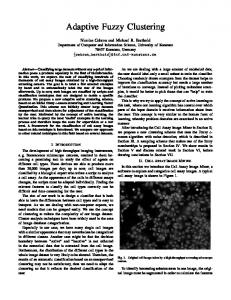
view 1
a2
d1
membership
view 2 d2 b2
c2
c1
support
0
b1
a1
1
actual measurement
D Figure 2: Fuzzy set for image length
C A
B
Figure 1: Cross ratio of four points in two views is (AB) (CD) / (AC) (BD). Figure 1 shows a set of four collinear points in the world, labeled A, B, C, and D, and two images of those points (a1…d1 in view 1 and a2…d2 in view 2). Because the cross-ratio is invariant, the image measurements (a1b1) (c1d1) / (a1c1) (b1d1) and (a2b2) (c2d2) / (a2c2) (b2d2) are the same as the actual (world) measurement (AB) (CD) / (AC) (BD). Therefore, if a sequence of four collinear points is a feature, with the cross-ratio of the four points as the constraint on that feature, then the feature can be detected in an image from any viewpoint where all four points are visible, regardless of relative orientation of the camera and the object. Each cross-ratio indicates that a set of four points in the image can correspond to one or more sequences of four collinear points in a model. If there are multiple models, then only models with similar cross-ratios to the detected one need to be considered. Therefore, each cross-ratio hypothesizes that the object in the image can match one or more models in the database (those models that have crossratios equal to the detected one). Although cross-ratios make good features and aid in object identification, by their very nature they are useless for pose determination. Since the cross-ratio is invariant to the elements of the pose (translation and rotation), the pose cannot be determined from the cross-ratio. Therefore, once a model has been identified and correspondences have been hypothesized, alternative techniques must be used for pose determination. 2. Finding Local Correspondences There are two aspects to finding local correspondences between the image and the model: finding appropriate features in the image, and determining the degree to which each image feature corresponds to a model feature. The first uses image-processing to locate points (in this case point sequences) of interest. The second uses matching (fuzzy compatibility) to determine to what degree each point sequence matches each model feature. Finding cross-ratio features in an image is not significantly different from finding vertex features as used
in [8]: first standard line detection algorithms find line segments in the image, then those segments are grouped into longer line segments and junctions (vertices) [5]. Each sequence of four consecutive junctions on the same line segment is a feature whose cross-ratio can be determined. Image and model features correspond when the constraint or measurement associated with the features are the same. Because images contain noise, occlusion, and spurious features, and because the feature extraction process itself is imperfect, it is very unlikely that the image and model measurements will be identical. Therefore, we model each measurement as a fuzzy set whose shape reflects the likely variation of the measurements. With Euclidean measurements, it is easy to develop such sets. As an example, Figure 2 shows a fuzzy set for the Euclidean length measurement, based on the actual measurement. The set is biased toward lengths that are longer than the measured length, because occlusion can shorten a segment’s apparent length, but never lengthen it. When using cross ratios, the effect of occlusion is not as straightforward. Consider a simple case where point D (in figure 1) is occluded. When the segment is detected, the four points will be A, B, C and a point E that results from the occlusion. E will fall somewhere between C and D, so CE < CD and BE < BD. If we define k as the portion of segment CD that is visible (k