Combining System Development and System Test in a Model-Centric Approach M. Born1, I. Schieferdecker1, O. Kath2, and C. Hirai3 1 Fraunhofer FOKUS, Kaiserin-Augusta-Alle 31, 10589 Berlin, Germany {born, schieferdecker}@fokus.fraunhofer.de 2 Technical University-Berlin, Franklinstr. 28/29, 10623 Berlin, Germany
[email protected] 3 Hitachi SDL,Yokohama , Japan
[email protected]
Abstract. In this paper we will present, how a model centric approach cannot only be used to rapidly develop the system but also at the same time to support the provision of the system tests which is an integral part of the overall system development. The key technology used to achieve this is a set of meta-tools which contains model repository generators and model transformer generators.
1 Introduction Model centric development of software system has recently become an important software engineering strategy for handling the complexity and the increasing requirements to larger and highly distributed software systems. This phenomena can be observed in different domains, from telecom over public sector to automotive and defense. The fundamental idea of model centric development is to replace the programming language code as the main artefact in the development process by models. These models exist on different levels of abstraction throughout the development process. They are not independent from each other and have various relations like trace or transformation relations. These relations allow to establish and maintain consistent views on the system, spanning over different abstraction levels from requirements through specifications and test cases. Furthermore, the degree of development automation is substantially increasing through the consequent application of model transformations wherever possible. Another important observation is that the overall resources which are spent for a development project are distributed to a large percentage (up to 70%) to the requirements/analysis phase and testing phase. Therefore, the model centric approach will only be a success if it is possible to reduce the development effort in exactly these phases without a lack of quality. The approach which we want to discuss in this contribution integrates the system design tightly with the development of system tests, starting at higher levels of abstraction. Our architecture for system development follows the idea of the Model Driven Architecture (MDA) as introduced by the Object Management Group [17]. Within the N. Guelfi (Ed.): RISE 2004, LNCS 3475, pp. 132 – 143, 2005. © Springer-Verlag Berlin Heidelberg 2005
Combining System Development and System Test
133
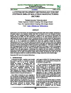
MDA, models are classified into platform independent models (PIM) and platform specific models (PSM). The term platform in the MDA sense refers to wide spread integration platforms like J2EE [12], CORBA Components [18] or Web services as well as to domain specific platforms like Autosar [16] for the automotive domain. The idea of MDA is that PIMs can be automatically transformed into PSMs and programming language code can be generated from PSMs. The test software can be modelled and developed in exactly the same way as the functional system software. Abstract testing artefacts are derived and modelled from the existing information in PIMs. These platform independent test models (PITs) can be transformed to platform specific test models (PSTs), potentially taking additional information from PSMs. Then, the programming language test code, i.e. the code of the test components of the test system, can be generated from the PSTs. This situation is depicted in Fig. 1, still completely independent from any particular modelling language, test language or programming language.
Platform Independent System Models
Platform Specific System Models
System Code
Platform Specific Test Models
Test Code
MOF Model Bus
Platform Independent Test Models
Fig. 1. The overall approach for combining system development and system test
In order to set up such an environment with concrete modeling, testing and programming languages, we apply a pattern which is used for each individual technique to be integrated. The pattern is applied for PIM, PSM, system code and for PIT, PST and test code. The pattern (Fig. 2) has the following steps: • The modeling principles and relations of the modeling technique have to be defined. • The modeling principles and relations have to be formalized in a metamodel. • A notation for the modeling technique has to be defined. • A process and guidelines of how to use the modeling technique have to be defined. • Possible connections to other modeling techniques in the overall process have to be defined.
134
M. Born et al.
Fig. 2. Pattern for integrating modelling techniques into a modeling environment
• A tool has to be provided for the modeling technique. • The tool has to be connected to the modeling environment. In order to achieve practically an integrated modelling environment with the described process, at least the following technical facilities are required: A facility to store and access the models independently from the modelling tools used to present and manipulate them and a facility to transform models into each other. The first one is usually a repository, the second one a transformer or code generator facility. In our approach we have used the Meta Object Facility (MOF [3]) as a formalism to describe the potential elements of models and to derive on one hand the repositories and on the other hand the transformers and code generators. The concrete techniques and tools we used for our integrated system and test development environment are: • an open modelling tool-suite medini (a MOF implementation [10]) for repositories and transformers, • the Unified Modelling Language (UML) profile for Enterprise distributed object computing (EDOC [2]) with Rational Rose [7] for PIM modelling, • the J2EE platform and Eclipse [8] for PSM modelling, • the TTCN-3 technology [6] and Eclipse for the PIT and PST modelling and • Java with Eclipse for coding. These concrete technologies are used for an experiment to show the feasibility of our approach. The most challenging part of this experiment is the transformation of the PIM and PSM to the PIT and PST with the constraint, that the resulting test code must fit with the system code which comes from the PSM to code transformation. In this contribution, we will present our initial ideas on this subject. The paper is structured as follows: We first introduce our medini toolset which provides the technology for tool integration via MOF repositories as well as a generic approach to model transformations. Then, we will show how the MDA based system development is done using EDOC and J2EE. After we have introduced the test development based on TTCN-3 we will discuss the transformations between the system models and the test models.
Combining System Development and System Test
135
2 The Open Modelling Environment The modelling environment that is used for the integration of development and test tools manages a set of model repositories based on MOF [3] and OCL (Object Constraint Language [4]) and provides means to access, store, read, and write models. The modelling environment is automatically produced by medini [10]. In Fig. 3, an overview of the modelling environment is depicted. The infrastructure forms an extendable bus containing a number of logically distinct repositories. System modelling and development tools are connected via their input and output pins to this model bus. The integration is achieved via model transformers. Model transformers are based on the semantic definition of the modelling techniques. They operate on the model repositories. The skeletons for the transformer are themselves automatically generated with medini.
Fig. 3. Overview of the Open Modelling Infrastructure (medini)
2.1 Repositories to Store Models and Other Artefacts In order to integrate a modelling technique into this modelling infrastructure at first, its modelling concepts need to be defined. That is, the semantics of each concept and the relations between concepts are defined in terms of a metamodel. This metamodel is the basis for the notation definition and for processes using artefacts of this modelling technique such as code generation from models. The processes are defined by use of model transformers. The notation, i.e. a human readable representation of a model, is used to present models to a user, e.g. a architects, modellers or developers. Beside the conceptual advantages of separating between concept definition, notation definition and transformation rules, this approach has also a technical
136
M. Born et al.
advantage: the modelling infrastructure can be directly generated from the metamodels independently of the particular notation or syntax for models. 2.2 Transformations Between Models in Repositories Secondly, the relations of the newly integrated modelling technique to existing modelling techniques of the modelling infrastructure need to be defined in terms of model transformers. The medini model transformer generator is an engine to produce such transformers. A model transformation is defined as the transition of source model objects to target model objects, both representing (parts of) models in a concrete domain (e.g. UML [5], C++, Java, etc.). In a repository centric approach like the one presented in this paper, these models are maintained within externally accessible repositories. Since objects are connected by links, the source and target models are rather graphs than loose entities. transformer „walks“ over source tree, calls transformation methods in right order and creates elements in target repository AttachesTo
+modelElement MofModelElement
MofModelElement
transformation_procedure_1 () MofFeature scope: Model::MofScopeKind visibility : Model::MofVisibilityKind
MofNamespace
MofTypedElement +tag 0..n
transformation_procedure_2 ()
MofStructuralFeature MofBehavioralFeature
1..n +constrainedE1 le..n ment
MofTypedElement
multiplicity : Model::MofMultiplicityTy... isChangeable: Boolean
MofTag
MofException +except 0..n
MofAttribute isDerived: Boolean
CanRaise
+constraint
MofReference referencedEnd: Model::MofAssociationEnd exposedEnd: Model::MofAssociationEnd
Constraints
transformation_procedure_3 ()
MofParameter 0..n MofConstraint expression:String language:String evaluationPolicy:Model::MofEvaluationKind constrainedElements:Model::MofModelElement
0..n +operation MofOperation isQuery : Boolean exceptions : Model::MofException
…
MofScopeKind instanceLevel classifierLevel
Source Model M1-level Instance (in repository) e.g. Detailed Design
MofEvaluationKind
MofConstant value:String
direction:Model::MofDirectionKind multiplicity: Model::MofMultiplicityType MofDirectionKind in_dir out_dir inout_dir return_dir
immediate deferred
Target Model M1-level Instance (in repository) e.g. Java Code
Fig. 4. Visualization of the Transformer Skeleton
To comprehend how a transformer works, it is essential to realize some requirements upon the process of transformation (see Fig 4). For each element in the source repository that is involved in a transformation, according rules must exist that accomplish the transformation task for this element. The rules may be combined in a fictive operation “do_transform” that contains the logic for the construction or modification of (a part of) the target model as result of a (set of) rule(s). Since model elements depend on each other, the call order of these transform operations is essential. This leads to a separation of the transformer into two parts: one part that iterates over a source model graph, i.e. the MOF level where system models are handled, and resolves dependencies between elements (the transformer skeleton, or “walker”) and a second part that performs the transformation task corresponding to the rules defined on top of the metamodels.
Combining System Development and System Test
137
3 System Development with EDOC and J2EE In order to establish a concrete tool chain for system development (and later for system test) we apply the integration pattern described in Section 1 to provide an abstract PIM modelling technique, a platform (and by that a PSM) on top of which the software components of the system will be integrated, and a programming language, which is used to finally implement the system components. For the prototype, we have chosen EDOC [2] as PIM modelling technique, J2EE [12] as target platform and by nature Java [9] as the programming language. The tools to support the modelling are Rational Rose [7] and Eclipse [8]. The integration of EDOC with the modelling infrastructure is done as follows. At first, the modelling concepts for the EDOC modelling technique have been defined in a MOF metamodel. All EDOC modelling concepts, there various relations and the constraints which have to be fulfilled by each concrete EDOC model are formalized within that MOF metamodel. The metamodel for EDOC is already part of the EDOC specification, although some work was needed to make it MOF-compliant. By applying medini to that metamodel, we obtain a MOF repository for the EDOC language with open interfaces to store, access and manipulate models in the repository by different clients. One client we connected to the repository is Rational Rose, where a plug-in realizes the EDOC UML profile. Hence, EDOC models can be defined by using Rose with the EDOC profile. They are stored in the repository and are ready for further processing. The generation of the EDOC repository from the EDOC metamodel and the connection of Rose with the EDOC UML profile are depicted in Fig. 5. EDOC modeling with Rose
0..1 Choreography Def +s uperty pe 0..n +s ubty pes
Ge ner ali zat io n
Is Choreography
PortOw nerDef
(1) Generate with medini
1 +the_owner
CompositionDef
(2) Connect client To repository
Us ageCo ntextDef
Ports Protoc olD ef IsC om pos ition
1 +the_protoc ol
+the_por t 0..n
PortDef + nam e : String + isSy nc hronous : Boolean + isTrans ac tional : Boolean + direction : ED OC ::ECA::C CA::D irectionTy pe... + pos tCondition : ED OC ::ECA::C CA::StatusD ef
Protoc olTy pe
Proc es s ComponentDef + granularity : EDOC::EC A::CC A::Granularity KindDef = Program + is Persis tent : Boolean + primitiv eKind : String + primitiv eSpec : String 1 +the_c om ponent
Interfac eD ef
Properties
+the_property 0..n
0..n +us ed_by Mu ltiPort Def
OperationPortD ef
Protoc olPortD ef
Property D ef initionD ef FlowPortDef
+c ons traints
Ty peProperty
0..n 0..n +the_port Granularit y Ki ndD ef
D irectionTy peDef
+ program + owned + shared
+ initiates + res ponds
+the_property + name : String + initial : String 0..1 + is Loc ked : Boolean +the_property 0..n
Flow Ty pe Property Type
0..1 +the_ty pe
+the_ty pe
Dat aElement Def 1 (from DocumentM odel)
EDOC metamodel
EDOC repository
Fig. 5. Modelling with EDOC
The next step is to transform EDOC models – which are stored in the EDOC repository – to platform specific models (J2EE). For that, we have to define the target for the transformation and the transformation rules. Along our general approach, a metamodel for J2EE is needed to generate a J2EE repository. The transformation target is then this repository, filled by the EDOC2J2EE transformer. For the J2EE metamodel, we took the Java metamodel from Netbeans and extended it with the concepts of J2EE. Fig. 6 shows a sub model of the J2EE metamodel. The Java Class
138
M. Born et al.
concept from the standard Java metamodel has been extended by the concept of Enterprise Beans and their interfaces. JavaClass (from Standard)
DeploymentDe scriptor + body : String
EnterpriseBean EJBInterface
EntityBean + primary_key : Cl assDescriptor
MessageDriv enBean
SessionBean
CMPEntityBean
BMPEntityBean StatelessSes sionBean
HomeInter face
RemoteInt erface
StatefullSess ionBean
LocalInter face
LocalHomeI nterface
Fig. 6. Sub model of the J2EE metamodel
Once the repository is available, we can define the EDOC to J2EE transformation rules between repositories of the source and target models. The mapping rules concentrate in the initial version on the static parts of an EDOC model. Static EDOC models are comparable with UML 2.0 static structures: the basic concept of EDOC is that of a process component which communicates via ports to its environment. Process components can have a structure; they may be composed out of other components. At the ports of a process component, the communication is described either with flows (messages), operations, interfaces or structured into protocols which are used to group other communication elements together. There are special process components which are used to model entities and their relations in EDOC. The initial transformation rules of the mentioned EDOC concepts to J2EE are summarized in Table 1. After the transformation has been performed by applying the transformation rules to an EDOC model in the EDOC repository, the generated J2EE model can be transformed to Java code which then can be deployed to a Java application server. We use Eclipse as Java development environment. Eclipse has an internal Java syntax tree which is automatically synchronized with the Java text files in the actual Eclipse project. Medini offers an Eclipse plug-in, which provides access for external clients to the Java syntax tree inside the Eclipse. To the outside, this plug-in behaves like a repository for Java. In fact, it offers exactly the API of a Java repository generated from the metamodel for Java without the J2EE extensions, i.e. it offers plain Java language constructs only. The only extension to the Java metamodel is the ability to attach Java doc tag information to Java language elements. This is because we use standard J2EE tools like Xdoclet and Lomboz [19] to generate all necessary artefacts for a J2EE application like deployment descriptors, configuration files etc. These tools expect Java sources with tags to generate the mentioned artefacts. Our tool chain contains another transformer which generates the Java sources with the proper tagging from the J2EE model in the J2EE repository. It uses the medini Eclipse plug-in as a
Combining System Development and System Test
139
target and the J2EE repository as a source. After being processed by Xdoclet/Lomboz, the application is ready for use. Table 1. Initial transformation rules from EDOC to J2EE EDOC Concept Process Component
J2EE concept Stateless session bean with remote interface and home interface, Entity Component with primary Entity beans with fields and home interface key Contained process components As process component but with local interfaces Flows, Operations Java messages as part of generated Java interfaces for their owning process components Protocols Java messages as part of generated Java interfaces, messages are recursively obtained from protocol structure (either operations, flows or sub-protocols) Package Java Package Composite Data Java class
4 System Test with TTCN-3 TTCN-3, the Testing and Test Control Notation [6][143], is the test specification and implementation language defined by the European Telecommunications Standards Institute (ETSI) for the precise definition of test procedures for black-box and grey-box testing. It is an extendible and powerful language, applicable to the specification of all types of reactive system tests over a variety of communication interfaces. TTCN-3 allows an easy and efficient description of complex distributed test behaviour in terms of sequences, alternatives, loops and parallel stimuli and responses. The test system can use any number of test components to perform test procedures in parallel. One essential benefit of TTCN-3 is that it enables the specification of tests in a platform independent manner. TTCN-3 provides the concepts of test components, their creation, communication links between them and to the system under test (SUT), their execution and termination on an abstract level, yet together with TTCN-3 execution interfaces to provide the realisation of concrete executable tests on different target test platforms. Features and capabilities being beyond TTCN-3 can be integrated into TTCN-3 by the use of external types, data and functions. TTCN-3 offers various presentation formats to serve the needs of different TTCN-3 application domains and users. The programming-like textual core notation (see Fig. 7 left hand side) suits best programmers and test developers. The core notation can be developed within a text editor of the users' choice and enables an easy integration into an overall test environment. The graphical format of TTCN-3 is based on Message Sequence Charts (MSC) and aids the visualization of test behaviour. It eases the reading, documentation and discussion of test procedures and is also well suited to the representation of test execution and analyzing of test results. The tabular presentation format highlights the structural aspects of a TTCN-3 module and in particular of structures of types and templates.
140
M. Born et al.
Since TTCN-3 is an abstract test specification language it can be used both for the definition of PIT and PST models. However, TTCN-3 does not well integrate into the approach described in Section 1 as it has been classically defined in form of a formal syntax and a semiformal semantics. Therefore, a TTCN-3 metamodel has been developed beforehand [15]. The TTCN-3 test metamodel (see Fig. 7 right hand side) defines the TTCN-3 concept space with additional support for the different presentation formats. It does not directly reflect the structure of a TTCN-3 modules but rather the structure of the TTCN-3 language definition. It is defined as a single package with concept structures for types and expressions, for modules and scopes, for declarations and for statements and operations. ´
Fig. 7. The change to a metamodel centric TTCN-3 language architecture
This metamodel is the basis for the generation of test repositories and model transformers that take a system model and generate test models in TTCN-3. The meta-model for TTCN-3 language was technically realized by using the Eclipse Modelling Framework provided by Eclipse [1]. This allowed us to integrate not only test development and execution tools but also to integrate the development of system artefacts with the development of test artefacts as described in the following.
5 The Combined Approach For the integration of the test development into system development, three transformations are of primary concern: • The PIM (platform-independent system model) to PIT (platform-independent system tests) – in our case an EDOC to TTCN-3 transformation. • The PSM (platform-specific system model) to PST (platform-specific system tests) – in our case a J2EE to TTCN-3 transformation. • The PIT to PST – in our case a TTCN-3 to TTCN-3 – transformation taking into account the specifics of the EDOC to J2EE transformation.
Combining System Development and System Test
141
In a first step, we concentrated on a structural PIM to PIT transformation. The transformation differentiates between process components/entities that need to be tested as part of the system under test (SUT) or that need to be emulated as part of the test system. Hence, the transformation is guided by the user which identifies the PIM parts being relevant for the test model. The default mapping for the main Component Metaclasses is given in the table below. Table 2. Initial transformation rules from EDOC ECA to TTCN-3 EDOC ECA Concept PackageDef DataTypeDef CompositeDataDef
ProcessComponentDef DataManager Entity Port Classes
TTCN-3 Concept TTCN-3 module Data type definition to be used within the test system and to be exchanged via TSI Data type definition to be used within the test system and to be exchanged via TSI, which are basically record structures with flattened inheritance Component type definition (with ports per interface) Component type definition (with local composite data variable) Component type definition (with local composite data variable) Port type definition
The transformation considers network sharable components only as those can be selected as a target for testing. Basically, the transformation does not consider containment hierarchies in the SUT as these are not visible from outside when using a black-box test approach. If however contained process components or entities are CUTs (components under test), then they need to be addressed within the SUT via the TTCN-3 address type. On the other side, if contained components are part of the test system and their behaviour is emulated, then they are mapped to separate test components interacting with test components representing process components or entities on higher level. Details of the port mapping are given in Table 3. Ports of CUTs or the test system are basically handled the same. The approach of generating test models from system models follows the basic principles outlined in [13] and [1]. Initially, the structural aspects of test generation, i.e. types, test components and their test configurations, have been considered only. In a second step, behavioural aspects of the tests will be addressed. For that, we will analyse how the EDOC protocol can be used as a basis for the behaviour of PITs. Basically, established test generation techniques used for the derivation of tests from finite state machines (represented by UML state charts) or message sequence charts (represented by UML interaction diagrams) will be used. The first uses mainly state or transition coverage methods, while the second uses branch or path coverage methods to derive the various test sequences. Still, the model transformers will generate basically test skeletons which need to be completed manually before they can be transformed into executable tests in Java and executed by use of the Testing Technologies’ TTCN-3 tool set [11].
142
M. Born et al. Table 3. Initial transformation rules from EDOC ECA Ports to TTCN-3 EDOC ECA Port Concept Synchronous port attribute Asynchronous port attribute Protocol port
Port direction Flow port Flow port: process component properties Operation port Multi-ports
Interfaces
TTCN-3 Concept Procedure-based port Message-based port In test system: message-based port plus test component representing the protocol behaviour In SUT: message-based port only Data types to be assigned to in, out our inout direction of a port Procedure- or message-based port Additional signature for setting and getting of properties Signatures In test system: a test component with ports for all coordinated interfaces In SUT: all coordinated interfaces are part of TSI (or are addressed via TTCN-3 address) Port types (possibly also test component)
6 Conclusion This paper presents a general approach of integrating modelling and development techniques for systems and tests into a modelling infrastructure. The integration is done via metamodels representing the concept space of the techniques. The metamodels are the basis to generate repositories and to manage, access and manipulate models. In addition, they are used as source and target for model transformers, which define the relations between techniques integrated into the modelling infrastructure. In a first step, we applied the modelling infrastructure to setup a development for EDOC. J2EE and Java on the system side and TTCN-3 and Java on the testing side. In a next step, the UML 2.0 testing profile (U2TP [1]) will be used for PITs instead of TTCN-3. The current restriction to focus on TTCN-3 only, is due to the unavailability of U2TP tooling. U2TP is an extension of UML 2.0 5 being based upon the UML metamodel. It follows the same fundamental principles of UML in that it provides concepts for the structural aspects of testing such as the definition of test components, test contexts and test system interfaces, and behavioural aspects of testing such as the definition of test procedures, test setup, execution and evaluation. The core UML is the basis for modelling and describing test artefacts. However, as software testing is based on a number of special test-related concepts these are provided by the testing profile as extensions to UML. U2TP is closer to the system modelling with the EDOC Profile for UML and will therefore be considered in our future work.
Combining System Development and System Test
143
Acknowledgment Part of the work described in this paper has been done within the context of the FP6/2003/IST/2 project Modelware which is partially funded by the European Commission.
References 1. Object Management Group: OMG ptc/04-04-02: UML 2.0 Testing Profile, Finalized Specification. 2. Object Management Group: OMG ptc/02-02-05: UML Profile for EDOC Final Adopted Specification. 3. Object Management Group: OMG ptc/03-10-04: MOF 2.0 Core Final Adopted Specification. 4. Object Management Group: OMG ptc/03-10-14: UML 2.0 OCL Final Adopted Specification. 5. Object Management Group: OMG ptc/03-08-02: UML 2.0 Superstructure Final Adopted Specification. 6. ETSI European Standard (ES) 201 873-1 version 2.2.1 (2003-02): The Testing and Test Control Notation version 3 (TTCN-3); Part 1: TTCN-3 Core Language. Also published as ITU-T Recommendation Z.140. 7. IBM/Rational: http://www-306.ibm.com/software/awdtools/developer/rose/ 8. Eclipse: Open Source Integrated Development Environment, www.eclipse.org. 9. Java: www.java.org 10. IKV++ Technologies AG: http://www.ikv.de/medini/. 11. Testing Technologies: TTCN-3 tool set, www.testingtech.de. 12. Sun Microsystems: Java 2 Platform, Enterprise Edition , http://java.sun.com/j2ee/. 13. I. Schieferdecker, Z.R. Dai, J. Grabowski, A. Rennoch. The UML 2.0 Testing Profile and its Relation to TTCN-3. Testing of Communicating Systems (Editors: D. Hogrefe, A. Wiles). Proc. of the 15th IFIP Intern. Conf. on Testing of Communicating Systems (TestCom2003), LNCS 2644, Springer, May 2003, pp. 79-94. 14. J. Grabowski, D. Hogrefe, G. Réthy, I. Schieferdecker, A. Wiles, C. Willcock. An Introduction into the Testing and Test Control Notation (TTCN-3). Computer Networks, Volume 42, Issue 3, Elsevier, June 2003. 15. I. Schieferdecker,. G. Din: A Metamodel for TTCN-3. 1st Intern. Workshop on Integrated Test Methodologies. Colocated with 24th Intern. Conference on Formal Description Techniques (FORTE 2004), Toledo, Spain, Sept. 2004. 16. Autosar: http://www.autosar.org/. 17. Object Management Group: Model Driven Architecture, http://www.omg.org/mda/. 18. Object Management Group: CORBA Component Model, OMG document formal/200206-65. 19. Lomboz: http://forge.objectweb.org/projects/lomboz.